


 Loading...
Graco 695, 795, 1095, 1595, Mark IV HD Operation Manual
...Operation, Parts
695 / 795 / 1095 / 1595 / Mark IV HD/ Mark V |
3A6342F |
HD/ Mark VII HD/ Mark X HD Electric Airless |
|
Sprayers |
EN |
For professional use only. Not approved for use in explosive atmospheres or hazardous locations. For portable airless spraying of architectural paints and coatings.
Models: 695 / 795 / 1095 / 1595 / Mark IV HD/ Mark V HD/ Mark VII HD/ Mark X HD
3300 psi (228 bar, 22.8 MPa) Maximum Working Pressure
See page 4 for additional model information.
Important Safety Instructions
Read all warnings and instructions in this manual and in Related Manuals listed on page 2 before using the equipment. Be familiar with the controls and the proper usage of the equipment. Save all instructions.
Use only genuine Graco replacement parts.
The use of non-Graco replacement parts may void warranty.

Before You Spray
Before You Spray
Review Warnings for Important Safety Information
Important! Read carefully and practice good safety habits.
Related Manuals
3A6285 |
Contractor PC Spray Gun |
|
311254 |
Flex Plus Spray Gun |
|
309495 |
Heavy-Duty InLine Spray Gun |
|
308491 |
Heavy-Duty Texture Spray Gun |
|
3A6584 |
Displacement Pump |
Manuals can also be found at www.graco.com |
3A6583 |
ProConnect™ Displacement |
|
|
Pump |
|
2 |
3A6342F |

Contents
Contents
Before You Spray . . . . . . . . . . . . . . . . . . . . . . . . . . . . . . . . . . . . . . . . . . . . . . . . . . . . . . 2
Contents . . . . . . . . . . . . . . . . . . . . . . . . . . . . . . . . . . . . . . . . . . . . . . . . . . . . . . . . . . . . . . 3 Models . . . . . . . . . . . . . . . . . . . . . . . . . . . . . . . . . . . . . . . . . . . . . . . . . . . . . . . . . . . . . . . 4 Warnings . . . . . . . . . . . . . . . . . . . . . . . . . . . . . . . . . . . . . . . . . . . . . . . . . . . . . . . . . . . . . 7 Know Your Sprayer . . . . . . . . . . . . . . . . . . . . . . . . . . . . . . . . . . . . . . . . . . . . . . . . . . . . 11 Know Your Controls . . . . . . . . . . . . . . . . . . . . . . . . . . . . . . . . . . . . . . . . . . . . . . . . . . . 14 Setup . . . . . . . . . . . . . . . . . . . . . . . . . . . . . . . . . . . . . . . . . . . . . . . . . . . . . . . . . . . . . . . 15
Assemble Your Sprayer . . . . . . . . . . . . . . . . . . . . . . . . . . . . . . . . . . . . . . . . . . . . . . 15 QuikReel™ . . . . . . . . . . . . . . . . . . . . . . . . . . . . . . . . . . . . . . . . . . . . . . . . . . . . . . . . 16 Grounding . . . . . . . . . . . . . . . . . . . . . . . . . . . . . . . . . . . . . . . . . . . . . . . . . . . . . . . . 17 Power Requirements . . . . . . . . . . . . . . . . . . . . . . . . . . . . . . . . . . . . . . . . . . . . . . . . 17 Extension Cords . . . . . . . . . . . . . . . . . . . . . . . . . . . . . . . . . . . . . . . . . . . . . . . . . . . . 17 Pails . . . . . . . . . . . . . . . . . . . . . . . . . . . . . . . . . . . . . . . . . . . . . . . . . . . . . . . . . . . . . 17
Start Up . . . . . . . . . . . . . . . . . . . . . . . . . . . . . . . . . . . . . . . . . . . . . . . . . . . . . . . . . . . . . 18
Pressure Relief Procedure . . . . . . . . . . . . . . . . . . . . . . . . . . . . . . . . . . . . . . . . . . . . 18 10/16 Amp Switch . . . . . . . . . . . . . . . . . . . . . . . . . . . . . . . . . . . . . . . . . . . . . . . . . . 19 15/20 Amp Switch . . . . . . . . . . . . . . . . . . . . . . . . . . . . . . . . . . . . . . . . . . . . . . . . . . 19 Flush Storage Fluid . . . . . . . . . . . . . . . . . . . . . . . . . . . . . . . . . . . . . . . . . . . . . . . . . 19 Strain the Paint . . . . . . . . . . . . . . . . . . . . . . . . . . . . . . . . . . . . . . . . . . . . . . . . . . . . 20 Fill Pump (Prime Pump) . . . . . . . . . . . . . . . . . . . . . . . . . . . . . . . . . . . . . . . . . . . . . . 21 Fill Spray Gun and Hose . . . . . . . . . . . . . . . . . . . . . . . . . . . . . . . . . . . . . . . . . . . . . 21 Refilling Paint Pail . . . . . . . . . . . . . . . . . . . . . . . . . . . . . . . . . . . . . . . . . . . . . . . . . . 22
Spraying . . . . . . . . . . . . . . . . . . . . . . . . . . . . . . . . . . . . . . . . . . . . . . . . . . . . . . . . . . . . . 23 Cleanup . . . . . . . . . . . . . . . . . . . . . . . . . . . . . . . . . . . . . . . . . . . . . . . . . . . . . . . . . . . . . 26 WatchDog . . . . . . . . . . . . . . . . . . . . . . . . . . . . . . . . . . . . . . . . . . . . . . . . . . . . . . . . . . . . 29 BlueLink™ App . . . . . . . . . . . . . . . . . . . . . . . . . . . . . . . . . . . . . . . . . . . . . . . . . . . . . . . 30 LED Display . . . . . . . . . . . . . . . . . . . . . . . . . . . . . . . . . . . . . . . . . . . . . . . . . . . . . . . . . . 32 Maintenance . . . . . . . . . . . . . . . . . . . . . . . . . . . . . . . . . . . . . . . . . . . . . . . . . . . . . . . . . . 35 Troubleshooting . . . . . . . . . . . . . . . . . . . . . . . . . . . . . . . . . . . . . . . . . . . . . . . . . . . . . . 36 695/795 Lo-Boy Standard Parts . . . . . . . . . . . . . . . . . . . . . . . . . . . . . . . . . . . . . . . . . . 50 695/795/Mark IV HD Hi-Boy Standard Parts . . . . . . . . . . . . . . . . . . . . . . . . . . . . . . . . 52 1095/1595/Mark V HD/Mark VII HD Hi-Boy Standard Parts . . . . . . . . . . . . . . . . . . . . 54 Mark X HD Standard Parts . . . . . . . . . . . . . . . . . . . . . . . . . . . . . . . . . . . . . . . . . . . . . . 56 695/795/Mark IV HD ProContractor Parts . . . . . . . . . . . . . . . . . . . . . . . . . . . . . . . . . . 58 1095/1595/Mark V HD/Mark VII HD ProContractor Parts . . . . . . . . . . . . . . . . . . . . . . 60 Mark X HD ProContractor Parts . . . . . . . . . . . . . . . . . . . . . . . . . . . . . . . . . . . . . . . . . . 62 1095/1595/Mark V HD /Mark VII HD IronMan Parts . . . . . . . . . . . . . . . . . . . . . . . . . . . 64 Mark X HD IronMan Parts . . . . . . . . . . . . . . . . . . . . . . . . . . . . . . . . . . . . . . . . . . . . . . . 66 ProContractor QuikReel . . . . . . . . . . . . . . . . . . . . . . . . . . . . . . . . . . . . . . . . . . . . . . . . 68 Spray Gun and Hose . . . . . . . . . . . . . . . . . . . . . . . . . . . . . . . . . . . . . . . . . . . . . . . . . . . 69 Filter . . . . . . . . . . . . . . . . . . . . . . . . . . . . . . . . . . . . . . . . . . . . . . . . . . . . . . . . . . . . . . . . 70 Control . . . . . . . . . . . . . . . . . . . . . . . . . . . . . . . . . . . . . . . . . . . . . . . . . . . . . . . . . . . . . . 72 Wiring Diagrams . . . . . . . . . . . . . . . . . . . . . . . . . . . . . . . . . . . . . . . . . . . . . . . . . . . . . . 74 Technical Specifications . . . . . . . . . . . . . . . . . . . . . . . . . . . . . . . . . . . . . . . . . . . . . . . 78 Compliance . . . . . . . . . . . . . . . . . . . . . . . . . . . . . . . . . . . . . . . . . . . . . . . . . . . . . . . . . . 86
Radio Frequency Approvals . . . . . . . . . . . . . . . . . . . . . . . . . . . . . . . . . . . . . . . . . . . 86 California Proposition 65 . . . . . . . . . . . . . . . . . . . . . . . . . . . . . . . . . . . . . . . . . . . . . 86
Graco Standard Warranty . . . . . . . . . . . . . . . . . . . . . . . . . . . . . . . . . . . . . . . . . . . . . . . 87 Graco Information . . . . . . . . . . . . . . . . . . . . . . . . . . . . . . . . . . . . . . . . . . . . . . . . . . . . . 88
3A6342F |
3 |

Models
Models
695 Models
|
|
|
Standard |
ProContractor |
|
|
|
Hi-Boy |
|
|
|
Standard |
|
|
|
|
Lo-Boy |
|
|
Voltage |
Model |
|
|
|
|
Ultra Max II 695 |
17E572 |
17E574 |
17E577 |
120 |
|
|
|
|
NEMA 5-15 |
Ultimate MX II 695 |
826222 |
826223 |
826224 |
230 CEE 7/7 |
Ultra Max II 695 |
|
17E632 |
17E635 |
230 Europe Multi |
Ultra Max II 695 |
|
17E633 |
17E636 |
110 UK |
Ultra Max II 695 |
|
17E634 |
17E637 |
230 ANZ/KR |
Ultra Max II 695 |
17E610 |
17E613 |
17E614 |
230 AP |
Ultra Max II 695 |
|
|
26C981 |
100 |
Ultra Max II 695 |
|
26C982 |
26C983 |
Japan/Taiwan |
|
|||
|
|
|
|
795 Models
Voltage |
Model |
Standard |
Standard |
ProContractor |
Lo-Boy |
Hi-Boy |
|
||
|
Ultra Max II 795 |
|
17E579 |
17E582 |
120 |
|
|
|
|
NEMA 5-15 |
Ultimate MX II 795 |
|
826225 |
826226 |
230 CEE 7/7 |
Ultra Max II 795 |
|
17E639 |
17E642 |
230 Europe Multi |
Ultra Max II 795 |
|
17E640 |
17E643 |
110 UK |
Ultra Max II 795 |
|
17E641 |
17E644 |
230 ANZ/KR |
Ultra Max II 795 |
17E616 |
17E617 |
17E619 |
230 AP |
Ultra Max II 795 |
|
|
26C984 |
100 |
Ultra Max II 795 |
|
26C985 |
26C986 |
Japan/Taiwan |
|
|||
|
|
|
|
|
4 |
|
|
|
3A6342F |

Models
1095 Models
|
|
Standard |
ProContractor |
|
|
|
Hi-Boy |
IronMan |
|
Voltage |
Model |
|
|
|
|
Ultra Max II 1095 |
17E583 |
17E585 |
17E586 |
120 |
|
|
|
|
NEMA 5-15 Ultimate MX II 1095 |
826227 |
826228 |
826229 |
|
230 CEE 7/7 |
Ultra Max II 1095 |
17E646 |
17E647 |
17E650 |
230 Europe Multi |
Ultra Max II 1095 |
|
17E648 |
|
230 ANZ/KR |
Ultra Max II 1095 |
17E620 |
17E621 |
17E623 |
230 AP |
Ultra Max II 1095 |
|
26C987 |
|
100 |
Ultra Max II 1095 |
26C988 |
26C989 |
|
Japan/Taiwan |
|
|||
|
|
|
|
|
1595 Models
|
|
Standard |
ProContractor |
IronMan |
|
|
Hi-Boy |
||
Voltage |
Model |
|
|
|
|
Ultimate MX II 1595 |
|
826233 |
|
120 |
|
|
|
|
NEMA 5-20 Ultra Max II 1595 |
|
17E593 |
|
|
120 |
Ultra Max II 1595 |
17E589 |
17E596 |
17E594 |
NEMA 5-15 Ultimate MX II 1595 |
826230 |
826232 |
826234 |
|
3A6342F |
5 |

Models
Mark HD Models
|
|
Standard |
ProContractor |
|
|
|
|
Hi-Boy |
IronMan |
||
Voltage |
Model |
|
|
|
|
120 |
Mark IV HD |
17E603 |
17E604 |
|
|
NEMA 5-15 |
|
||||
|
|
|
|
||
120 |
Mark V HD |
|
17E628 |
|
|
NEMA 5-20 |
|
|
|||
|
|
|
|
||
120 |
Mark V HD |
17E605 |
17E606 |
17E607 |
|
NEMA 5-15 |
|||||
|
|
|
|
||
230 |
Mark X HD |
17E608 |
17E609 |
|
|
NEMA L6-30 |
|
||||
|
|
|
|
||
|
Mark IV HD |
17E651 |
17E653 |
|
|
230 CEE 7/7 |
Mark V HD |
17E655 |
17E660 |
17E664 |
|
Mark VII HD |
17E665 |
17E667 |
17H895 |
||
|
|||||
|
Mark X HD |
17E669 |
17E671 |
17H897 |
|
|
Mark IV HD |
17E652 |
17E654 |
|
|
230 Europe |
Mark V HD |
|
17E661 |
|
|
Multi |
Mark VII HD |
17E666 |
17E668 |
17H896 |
|
|
Mark XHD |
17E670 |
17E672 |
17H898 |
|
110 UK |
Mark V HD |
17E659 |
17E662 |
|
|
|
Mark V HD |
|
17E663 |
17E629 |
|
230 ANZ/KR |
Mark VII HD |
|
26C993 |
|
|
|
Mark X HD |
|
17E674 |
|
|
|
Mark IV HD |
17E624 |
|
|
|
230 AP |
Mark V HD |
17E657 |
26C990 |
|
|
Mark VII HD |
26C992 |
|
|
||
|
|
|
|||
|
Mark X HD |
17E673 |
26C995 |
|
|
100 |
Mark V HD |
|
26C991 |
|
|
Japan/Taiwan |
|
|
|||
|
|
|
|
6 |
3A6342F |
Warnings
Warnings
The following warnings are for the setup, use, grounding, maintenance, and repair of this equipment. The exclamation point symbol alerts you to a general warning and the hazard symbols refer to procedure-specific risks. When these symbols appear in the body of this manual or on warning labels, refer back to these Warnings. Product-specific hazard symbols and warnings not covered in this section may appear throughout the body of this manual where applicable.
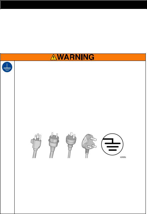
GROUNDING
This product must be grounded. In the event of an electrical short circuit, grounding reduces the risk of electric shock by providing an escape wire for the electric current. This product is equipped with a cord having a grounding wire with an appropriate grounding plug. The plug must be plugged into an outlet that is properly installed and grounded in accordance with all local codes and ordinances.
•Improper installation of the grounding plug is able to result in a risk of electric shock.
•When repair or replacement of the cord or plug is required, do not connect the grounding wire to either flat blade terminal.
•The wire with insulation having an outer surface that is green with or without yellow stripes is the grounding wire.
•Check with a qualified electrician or serviceman when the grounding instructions are not completely understood, or when in doubt as to whether the product is properly grounded.
•Do not modify the plug provided; if it does not fit the outlet, have the proper outlet installed by a qualified electrician.
•This product is for use on a nominal 120 V or 230 V circuit and has a grounding plug similar to the plugs illustrated in the figure below.
120V US 230V |
230V ANZ 230V India |
•Only connect the product to an outlet having the same configuration as the plug.
•Do not use a 3-to-2 adapter with this product.
Extension Cords:
•Use only a 3-wire extension cord that has a grounding plug and a grounding receptacle that accepts the plug on the product.
•Make sure your extension cord is not damaged. If an extension cord is necessary use 12 AWG (2.5mm2) minimum to carry the current that the product draws.
•An undersized cord results in a drop in line voltage and loss of power and overheating.
Conductor Size |
|
Length |
AWG (American Wire Gauge) |
Metric |
Maximum |
12 |
2.5 mm2 |
50 ft. (15 m) |
3A6342F |
7 |

Warnings
FIRE AND EXPLOSION HAZARD
Flammable fumes, such as solvent and paint fumes, in work area can ignite or explode. To help prevent fire and explosion:
•Do not spray flammable or combustible materials near an open flame or sources of ignition such as cigarettes, motors, and electrical equipment.
•Paint or solvent flowing through the equipment is able to result in static electricity. Static
electricity creates a risk of fire or explosion in the presence of paint or solvent fumes. All parts of the spray system, including the pump, Hose assembly, Spray Gun, and objects in and around the spray area shall be properly grounded to protect against static discharge and sparks. Use Graco conductive or grounded high-pressure airless paint sprayer hoses.
•Verify that all containers and collection systems are grounded to prevent static discharge. Do not use pail liners unless they are anti-static or conductive.
•Connect to a grounded outlet and use grounded extensions cords. Do not use a 3-to-2 adapter.
•Do not use a paint or a solvent containing halogenated hydrocarbons.
•Do not spray flammable or combustible liquids in a confined area.
•Keep spray area well-ventilated. Keep a good supply of fresh air moving through the area.
•Sprayer generates sparks. Keep pump assembly in a well ventilated area a least 20 feet
(6.1 m) from the spray area when spraying, flushing, cleaning, or servicing. Do not spray pump assembly.
•Do not smoke in the spray area or spray where sparks or flame is present.
•Do not operate light switches, engines, or similar spark producing products in the spray area.
•Keep area clean and free of paint or solvent containers, rags, and other flammable materials.
•Know the contents of the paints and solvents being sprayed. Read all Safety Data Sheets
(SDSs) and container labels provided with the paints and solvents. Follow the paint and solvents manufacturer’s safety instructions.
•Keep a working fire extinguisher in the work area.
ELECTRIC SHOCK HAZARD
This equipment must be grounded. Improper grounding, setup, or usage of the system can cause electric shock.
•Turn off and disconnect power cord before servicing equipment.
•Connect only to grounded electrical outlets.
•Use only 3-wire extension cords.
•Ensure ground prongs are intact on power and extension cords.
•Do not expose to rain. Store indoors.
•Wait five minutes after disconnecting power cord before servicing.
8 |
3A6342F |
Warnings
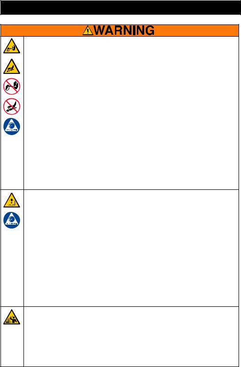
SKIN INJECTION HAZARD
High-pressure spray is able to inject toxins into the body and cause serious bodily injury. In the event that injection occurs, get immediate surgical treatment.
•Do not aim the Spray Gun at, or spray any person or animal.
•Keep hands and other body parts away from the discharge. For example, do not try to stop leaks with any part of the body.
•Always use the nozzle tip guard. Do not spray without nozzle tip guard in place.
•Use Graco nozzle tips.
•Use caution when cleaning and changing nozzle tips. In the case where the nozzle tip
clogs while spraying, follow the Pressure Relief Procedure for turning off the unit and relieving the pressure before removing the nozzle tip to clean.
•Equipment maintains pressure after power is shut off. Do not leave the equipment
energized or under pressure while unattended. Follow the Pressure Relief Procedure when the equipment is unattended or not in use, and before servicing, cleaning, or removing parts.
•Check hoses and parts for signs of damage. Replace any damaged hoses or parts.
•This system is capable of producing 3000 psi (207 bar, 20.7 MPa). Use Graco
replacement parts or accessories that are rated a minimum of 3000 psi (207 bar, 20.7 MPa).
•Always engage the Trigger Lock when not spraying. Verify the Trigger Lock is functioning properly.
•Verify that all connections are secure before operating the unit.
•Know how to stop the unit and bleed pressure quickly. Be thoroughly familiar with the controls.
EQUIPMENT MISUSE HAZARD
Misuse can cause death or serious injury.
•Always wear appropriate gloves, eye protection, and a respirator or mask when painting.
•Do not operate or spray near children. Keep children away from equipment at all times.
•Do not overreach or stand on an unstable support. Keep effective footing and balance at all times.
•Stay alert and watch what you are doing.
•Do not operate the unit when fatigued or under the influence of drugs or alcohol.
•Do not kink or over-bend the Hose.
•Do not expose the Hose to temperatures or to pressures in excess of those specified by Graco.
•Do not use the Hose as a strength member to pull or lift the equipment.
•Do not spray with a Hose shorter than 25 feet.
•Do not alter or modify equipment. Alterations or modifications may void agency approvals and create safety hazards.
•Make sure all equipment is rated and approved for the environment in which you are using it.
PRESSURIZED ALUMINUM PARTS HAZARD
Use of fluids that are incompatible with aluminum in pressurized equipment can cause serious chemical reaction and equipment rupture. Failure to follow this warning can result in death, serious injury, or property damage.
•Do not use 1,1,1-trichloroethane, methylene chloride, other halogenated hydrocarbon solvents or fluids containing such solvents.
•Do not use chlorine bleach.
•Many other fluids may contain chemicals that can react with aluminum. Contact your material supplier for compatibility.
3A6342F |
9 |

Warnings
MOVING PARTS HAZARD
Moving parts can pinch, cut, or amputate fingers and other body parts.
•Keep clear of moving parts.
•Do not operate equipment with protective guards or covers removed.
•Equipment can start without warning. Before checking, moving, or servicing equipment, follow the Pressure Relief Procedure and disconnect all power sources.
TOXIC FLUID OR FUMES HAZARD
Toxic fluids or fumes can cause serious injury or death if splashed in the eyes or on skin, inhaled, or swallowed.
•Read Safety Data Sheets (SDSs) to know the specific hazards of the fluids you are using.
•Store hazardous fluid in approved containers, and dispose of it according to applicable guidelines.
PERSONAL PROTECTIVE EQUIPMENT
Wear appropriate protective equipment when in the work area to help prevent serious injury, including eye injury, hearing loss, inhalation of toxic fumes, and burns. This protective equipment includes but is not limited to:
•Protective eyewear, and hearing protection.
•Respirators, protective clothing, and gloves as recommended by the fluid and solvent manufacturer.
10 |
3A6342F |
Know Your Sprayer
Know Your Sprayer
695 / 795 / 1095 / 1595 / Mark IV HD/ Mark V HD/ Mark VII HD/ Mark X HD Standard Models:
A |
ON/OFF Switch |
|
|
B |
Pressure Control Knob |
|
|
C |
Prime / Spray Valve |
|
|
D |
Spray Gun |
|
|
E |
Spray Tip |
|
|
F |
Trigger Lock |
|
|
G |
Filter |
|
|
H |
Pump |
|
|
I |
Suction Tube |
|
|
J |
Inlet Strainer |
|
|
K |
Drain Tube |
|
|
L |
Hose |
|
|
M |
Whip Hose (not included on all models) |
|
|
N |
Pressure Gauge (not included on all units) |
|
|
O |
Amp Switch (not equipped on all units) |
|
|
P |
Unit/Serial Tag |
|
|
3A6342F |
11 |

Know Your Sprayer
695 / 795 / 1095 / 1595 Mark IV HD/ Mark V HD/ Mark VII HD/ Mark X HD ProContractor Models:
A |
LED Display (not included on all units) |
|
|
B |
ON/OFF Switch |
|
|
C |
Pressure Control Knob |
|
|
D |
Prime / Spray Valve |
|
|
E |
Spray Gun |
|
|
F |
Spray Tip |
|
|
G |
Trigger Lock |
|
|
H |
Filter |
|
|
I |
Pump |
|
|
J |
Suction Tube |
|
|
K |
Inlet Strainer |
|
|
L |
Drain Tube |
|
|
M |
Hose |
|
|
N |
QuikReel™ |
|
|
O |
ProConnect Pump Rod Pull Feature |
|
|
P |
Amp Switch (not equipped on all units) |
|
|
Q |
Unit/Serial Tag |
|
|
R |
ProConnect II |
|
|
12 |
3A6342F |

Know Your Sprayer
1095 / 1595 / Mark V HD IronMan Models:
A |
LED Display (not included on all units) |
|
|
B |
ON/OFF Switch |
|
|
C |
Pressure Control Knob |
|
|
D |
Prime / Spray Valve |
|
|
E |
Spray Gun |
|
|
F |
Spray Tip |
|
|
G |
Trigger Lock |
|
|
H |
Filter |
|
|
I |
Pump |
|
|
J |
Suction Tube |
|
|
K |
Inlet Strainer |
|
|
L |
Drain Tube |
|
|
M |
Hose |
|
|
N |
Whip Hose (not included on all models) |
|
|
O |
Pressure Gauge (not included on all units) |
|
|
P |
Amp Switch (not equipped on all units) |
|
|
Q |
ProConnect Pump Rod Pull Feature |
|
|
R |
Unit/Serial Tag |
|
|
S |
ProConnect II |
|
|
3A6342F |
13 |

Know Your Controls
Know Your Controls
|
|
|
|
|
|
|
|
|
|
The ON/OFF power switch controls the |
|
|
|
|
|
|
|
|
|
|
power to your sprayer. |
|
|
|
|
|
|
|
|
|
|
|
|
|
|
|
|
|
|
|
|
|
The Pressure Control Knob increases or |
|
|
|
|
|
|
|
|
|
|
decreases the pressure. It also has a setting |
|
|
|
|
|
|
|
|
|
|
for Prime/Slow and FastFlush™. |
|
|
|
|
|
|
|
|
|
|
|
|
|
|
|
|
|
|
|
|
||
|
PRIME/SPRAY |
|
|
|
|
|||||
|
|
|
|
|
|
|
|
|
|
The Prime/Spray Valve directs the fluid to |
|
|
|
|
|
|
|
|
|
|
either the Drain Tube or the Hose and Spray |
|
|
|
|
|
|
|
|
|
|
Gun. It is used to prime the sprayer, which |
|
|
|
|
|
|
|
|
|
|
means to evacuate the air out of the pump, |
|
|
|
|
|
|
|
|
|
Hose, and Spray Gun. |
|
|
|
|
Prime |
|||||||
|
|
|
|
Spray |
||||||
|
|
|
|
|
|
|
|
|
|
Your Spray Gun will not spray if there is air in |
|
|
|
|
|
|
|
|
|
|
|
|
|
|
|
|
|
|
|
|
|
the system. It is necessary to prime the |
|
|
|
|
|
|
|
|
|
|
pump, Hose, and Spray Gun any time air |
|
|
|
|
|
|
|
|
|
|
enters the Suction Tube. |
|
|
|
|
|
|
|
|
|
|
|
SPRAY TIP |
|
|
|
|
|
|||||
|
|
|
|
|
|
|
||||
|
|
Spray |
|
|||||||
|
|
|
|
Unclog |
The Spray Tip is the key to airless spray |
|||||
|
|
|
|
|
|
|
|
|
|
|
|
|
|
|
|
|
|
|
|
|
technology. High pressure paint pumped |
|
|
|
|
|
|
|
|
|
|
through the very small hole in the Spray Tip |
|
|
|
|
|
|
|
|
|
|
comes out as a spray. |
|
|
|
|
|
|
|
|
|
|
The Spray Tip has the ability to be reversed |
|
|
|
|
|
|
|
|
|
|
and quickly clear clogs. |
|
|
|
|
|
|
|
|
|
|
|
14 |
3A6342F |

Setup
Setup
Assemble Your Sprayer
When unpacking sprayer for the first time or after long term storage perform setup procedure.
1.All sprayers except ProContractor:
Connect Graco airless Hose to sprayer. If whip Hose is included, attach to end of airless Hose. Use wrenches to tighten securely.
2.Connect Spray Gun to other end of Hose. Use wrenches to tighten securely.
3.When unpacking sprayer for the first time remove packaging materials from inlet strainer. After long term storage check inlet strainer for clogs and debris.
4.Fill throat packing nut with Graco TSL™ to prevent premature packing wear. Do this each time you spray.
a.Place the TSL bottle nozzle into the top center opening in the grill at the front of the sprayer.
b.Squeeze bottle to dispense enough TSL to fill the space between the pump rod and packing nut seal.
5.Ensure Spray Tip is properly inserted into the Spray Tip Guard, and the Spray Tip Guard assembly is tightened securely to the Spray Gun. Refer to separate Spray Gun manual.
6.Perform the Pressure Relief Procedure, page 18.
3A6342F |
15 |

Setup
QuikReel™
(ProContractor models only)
Moving parts can pinch, cut or amputate fingers and other body parts. To avoid injury from moving parts, be sure to keep your head clear of QuikReel while winding up Hose.
1.Make sure Hose is routed through hose guide.
2.Lift and turn pivot lock 90° to unlock Hose Reel. Pull on Hose to remove it from Hose Reel.
3.Pull reel handle down and out. Turn clockwise to reel in Hose.
NOTE: QuikReel can be locked into two positions: Usage (A) and Storage (B).
16 |
3A6342F |
Setup
Grounding
The equipment must be grounded to reduce the risk of static sparking and electric shock. An electric or static spark can cause fumes to ignite or explode. An improper ground can cause electric shock. A good ground provides an escape wire for the electric current.
This sprayer is equipped with a power cord that has a ground wire and an appropriate grounding plug.
The plug must be plugged into an outlet that is properly installed and grounded in accordance with all local codes and ordinances.
Do not modify the plug provided; if it does not fit the outlet, have the proper outlet installed by a qualified electrician.
Power Requirements
•100-120V units require 100-120 VAC, 50/60 Hz, 15A, 1 phase.
•230V units require 230 VAC, 50/60 HZ,
10A-16A, 1 phase.
Extension Cords
Use an extension cord with an undamaged ground contact. If an extension cord is necessary, use a 3-wire, 12 AWG (2.5 mm2) minimum.
NOTE: Smaller gauge or longer extension cords may reduce sprayer performance.
Pails
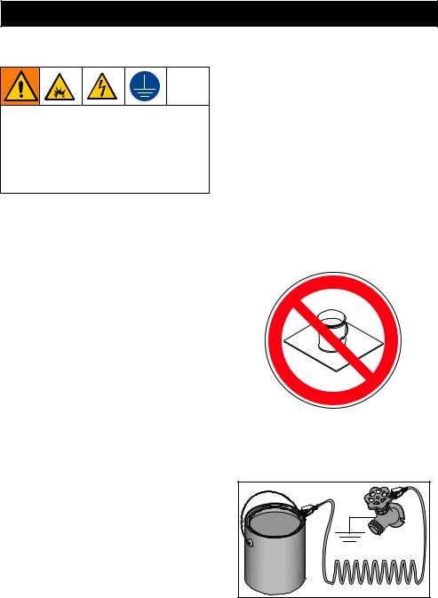
Solvent and oil-based fluids: follow local code. Use only conductive metal pails, placed on a grounded surface such as concrete.
Do not place pail on a non-conductive surface such as paper or cardboard which interrupts grounding continuity.
Always ground a metal pail: connect a ground wire to the pail. Clamp one end to the pail and the other end to a true earth ground such as a water pipe.
ti24584a |
3A6342F |
17 |
Start Up
Start Up
Pressure Relief Procedure
Follow the Pressure Relief Procedure whenever you see this symbol.
This equipment stays pressurized until pressure is manually relieved. To help prevent serious injury from pressurized fluid, such as skin injection or splashed fluid, follow the Pressure Relief Procedure whenever sprayer is stopped and before sprayer is cleaned or checked, and before equipment is serviced.
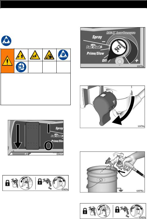
1.Turn ON/OFF switch to the OFF position.
2.Engage the Trigger Lock. Always engage the Trigger Lock when sprayer is stopped to prevent the Spray Gun from being triggered accidentally.
4.Put Drain Tube into a waste pail and turn Prime/Spray Valve down to PRIME position to relieve pressure.
5.Hold the Spray Gun firmly to a grounded pail. Point Spray Gun into pail. Disengage the Trigger Lock and trigger the Spray Gun to relieve pressure.
3. Turn Pressure Control Knob to OFF (all |
6. Engage the Trigger Lock. |
the way counterclockwise). |
18 |
3A6342F |

Start Up
7.If you suspect the spray tip or Hose is clogged or that pressure has not been fully relieved:
a.VERY SLOWLY loosen the tip guard retaining nut or the Hose end coupling to relieve pressure gradually.
b.Loosen the nut or coupling completely.
c.Clear Hose or tip obstruction.
NOTE: Leave Prime/Spray Valve in the PRIME position until you are ready to spray.
10/16 Amp Switch
(230V Mark VII and Mark X units)
Use 16A setting if 16A circuit is available for maximum sprayer performance. Otherwise, use 10A setting.
15/20 Amp Switch
(120V 1595 and Mark V units)
Use 20A setting if 20A circuit is available for maximum sprayer performance. Otherwise, use 15A setting.
Flush Storage Fluid
It is important that you flush storage fluid from the sprayer before using it.
1.Make certain ON/OFF switch is OFF.
2.Separate Drain Tube (smaller) from Suction Tube (larger). Place Drain Tube in a waste pail.
3.Submerge Suction Tube into grounded pail filled with appropriate flushing fluid.
3A6342F |
19 |

Start Up
4.Make certain Prime/Spray Valve is down in the PRIME position.
10.Turn the ON/OFF switch to OFF position.
5.Make certain the Pressure Control Knob is set to OFF (all the way counterclockwise).
6.Plug power cord into a properly grounded electrical outlet.
7.Turn ON/OFF switch to ON position.
8.Turn Pressure Control Knob to Prime/Slow in order to start the motor. Flushing fluid will flow up the Suction Tube and out the Drain Tube into the waste pail.
Strain the Paint
Disposable paint strainer bags are used to remove coarse particles and debris from new or previously opened paint or stain, and are available where paint is sold. To avoid priming problems and Spray Tip clogs it is recommended to strain all paints and stains before spraying. Stretch a disposable paint strainer bag over a clean pail and pour the paint through the strainer.
ti26894a |
High-pressure spray is able to inject toxins into the body and cause serious bodily injury. Do not stop leaks with hand or rag.
9.When you see flushing fluid exiting the Drain Tube, turn Pressure Control Knob to FastFlush setting and allow unit to flush for 30-60 seconds.
20 |
3A6342F |
Start Up
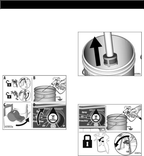
Fill Pump (Prime Pump)
The Prime/Spray Valve directs the fluid to either the Drain Tube or the Hose and Spray Gun. It is used to prime the sprayer, which means to evacuate the air out of the pump, Hose, and Spray Gun.
Your Spray Gun will not spray if there is air in the system. It is necessary to prime the pump, Hose, and Spray Gun any time air enters the Suction Tube.
1.Move Suction Tube to paint pail and submerge Suction Tube in paint. Place Drain Tube in waste pail.
2.Turn Pressure Control Knob to Prime/Slow.
3.Turn ON/OFF switch to ON position to start motor.
4.Wait to see paint coming out of Drain Tube.
5.Turn Pressure Control Knob to OFF (all the way counterclockwise) to disengage motor.
Fill Spray Gun and Hose
1.Remove Spray Tip Guard.
2.Hold Spray Gun against waste pail. Point Spray Gun into waste pail.
a.Disengage Trigger Lock (A).
b.Pull and hold Spray Gun trigger (B).
c.Turn Prime/Spray Valve horizontal to SPRAY position (C).
d.Turn Pressure Control Knob to Prime/Slow (D).
3A6342F |
21 |

Start Up
3.Continue to trigger Spray Gun into waste pail until only paint comes out of the Spray Gun.
4.Release trigger. Engage Trigger Lock.
High-pressure spray is able to inject toxins into the body and cause serious bodily injury. Do not stop leaks with hand or rag.
NOTE: Inspect for leaks. If leaking occurs, perform Pressure Relief Procedure, page 18, then tighten all fittings and repeat Fill Pump (Prime Pump), page 21.
5.Transfer Drain Tube to paint pail.
6.Install Spray Tip Guard. Rotate Spray Tip back to SPRAY position and ensure the Spray Tip Guard is tight.
Spray
You are now ready to spray!
NOTE: It is normal for the motor to stop once the sprayer is primed and under pressure.
Refilling Paint Pail
When the paint pail runs low and the Spray Gun stops spraying, refill the paint pail and repeat the Fill Pump (Prime Pump) procedure, then the Fill Spray Gun and Hose procedure.
22 |
3A6342F |
Spraying
Spraying
Start
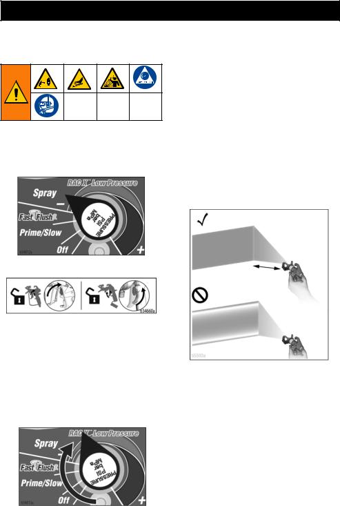
1.Turn pressure control knob to SPRAY position.
2.Disengage Trigger Lock.
Adjust Pressure Control
1.For best spray results with lowest overspray, begin with the Pressure Control Knob adjusted to the lowest spray setting.
2.If needed, increase Pressure Control Knob setting to the lowest spray setting that results in an acceptable spray pattern.
Spray Pattern Quality
A good spray pattern is evenly distributed as it hits the surface.
•Spray should be atomized (evenly distributed, no gaps at edges).
•Increase Pressure Control Knob if needed until spray is even and without gaps at edges.
•Spray Tip may be worn or a smaller tip may be needed.
•Material may need to be thinned. If material needs to be thinned follow manufacturer’s recommendations.
Good Spray Pattern
12 in. (30 cm) from surface
TAILS - Gaps at edges
Pressure too low
Tip Wear
3A6342F |
23 |

Spraying
Spray Techniques
Use a piece of scrap cardboard to practice these basic spraying techniques before you begin spraying the surface.
•Hold Spray Gun 12 in. (30 cm) from surface and aim straight at surface. Tilting Spray Gun to direct spray angle causes an uneven finish.
•Flex wrist to keep Spray Gun pointed straight. Fanning Spray Gun to direct spray at angle causes uneven finish.
EVEN FINISH
even finish
UNEVEN FINISH
uneven finish
EVEN FINISH
thin |
UNEVEN FINISH |
thin |
thick |
Triggering Spray Gun
Pull trigger after starting stroke. Release trigger before end of stroke. Spray Gun must be moving when trigger is pulled and released.
START |
|
|
|
CONTINUE |
RELEASE |
|
|
|
TRIGGER |
|
END |
||||
STROKE |
|
GUN |
|
STROKE |
TRIGGER |
STROKE |
|
|
|
|
|
|
|
|
|
Aiming Spray Gun
Aim center of spray of Spray Gun at bottom edge of previous stroke, overlapping each stroke by half.
Horizontal Spray
Vertical
Spray
24 |
3A6342F |

Spraying
Clear Spray Tip Clog
In the event that particles or debris clog the Spray Tip, the Spray Tip can be reversed to quickly and easily clear particles without disassembling the sprayer.
See Strain the Paint, page 20, for additional information.
1.Engage Trigger Lock. Rotate Spray Tip to UNCLOG position. Ensure spray tip remains fully seated, pushed all the way into the Spray Tip Guard. Disengage Trigger Lock. Trigger Spray Gun at waste area to clear clog.
UNCLOG
NOTE: If Spray Tip is difficult to rotate when turning to the UNCLOG position perform,
Pressure Relief Procedure, page 18, then turn Prime/Spray Valve horizontal to SPRAY position and repeat step 1.
2.Engage Trigger Lock. Rotate Spray Tip back to SPRAY position. Disengage Trigger Lock and continue spraying.
SPRAY
Spray Tip Installation
To avoid serious injury from skin injection do not put your hand in front of the spray tip when installing or removing the spray tip and spray tip guard.
To prevent Spray Tip leaks make certain Spray Tip and Spray Tip Guard are installed properly. Refer to separate Spray Gun manual for procedure to remove and install Spray Tip, Seal, and Spray Tip Guard.
3A6342F |
25 |

Cleanup
Cleanup
1.Perform Pressure Relief Procedure, page 18.
2.Remove Spray Tip Guard and Spray Tip. For additional information, see separate Spray Gun manual.
ti24592a
Clean Drain Tube
3.Remove Suction Tube and Drain Tube from paint; wipe excess paint off outside of Suction Tube.
4.Place Suction Tube in appropriate flushing fluid. Place Drain Tube in waste pail.
5.To flush Drain Tube and pump turn Prime/Spray Valve down to PRIME position.
6.Turn pressure control to Prime/Slow and turn ON/OFF switch to ON position to start the motor. Flushing fluid will flow up the Suction Tube and out the Drain Tube into the waste pail. Allow flushing fluid to flow out of Drain Tube for 5 seconds.
7.Turn Pressure Control Knob to OFF setting (all the way counterclockwise).
26 |
3A6342F |
Cleanup
Clean Hose and Spray Gun
8.Hold Spray Gun against a grounded metal waste pail. Point Spray Gun into waste pail.
a.Disengage Trigger Lock (A).
b.Pull and hold Spray Gun trigger (B).
c.Turn Prime/Spray Valve horizontal to SPRAY position (C).
d.Turn pressure control to 12 o’ clock position to begin flushing (D). (For optimal cleaning performance, the Pressure Control Knob can be turned to the FastFlush setting.)
12.Remove Suction Tube from flushing fluid so that air can enter the pump and push flushing fluid out of the Hose and Spray Gun.
13.Trigger Spray Gun into flushing pail and turn Pressure Control Knob to 12 o’ clock position to purge fluid from Hose.
14.When flushing fluid has been purged, release trigger. Engage Trigger Lock.
9.Continue flushing until flushing fluid appears clear.
10.Turn Pressure Control Knob to OFF (all the way counterclockwise).
11.Stop triggering Spray Gun.
3A6342F |
27 |
Loading...