


Instructions–Parts List
1:1 RATIO |
|
|
TRITONR 308 |
309303V |
|
Diaphragm Pump |
||
ENG |
||
|
|
Used to pump waterborne and solvent–based paints and catalysts. For professional use only.
115 psi (0.8 MPa, 8 bar) Maximum Fluid Working Pressure 115 psi (0.8 MPa, 8 bar) Maximum Air Input Pressure
Part No. 233500 Aluminum Pump, Series D, npt threads
Part No. 233501 Stainless Steel Pump, Series C, npt threads
Part No. 233776 Aluminum Pump, Series C, BSPP threads
Part No. 233777 Stainless Steel, Series C, BSPP threads
U.S. and Foreign Patents Pending
Important Safety Instructions
Read all warnings and instructions in this manual.
Save these instructions.
Part No. 233501 Shown |
ti1029a |
|

Table of Contents
Safety Warnings . . . . . . . . . . . . . . . . . . . . . . . . . . . . . . . 3
Installation . . . . . . . . . . . . . . . . . . . . . . . . . . . . . . . . . . . . . 6
Operation . . . . . . . . . . . . . . . . . . . . . . . . . . . . . . . . . . . . 11
Maintenance . . . . . . . . . . . . . . . . . . . . . . . . . . . . . . . . . . 12
Troubleshooting . . . . . . . . . . . . . . . . . . . . . . . . . . . . . . . 12
Service
Remove the Fluid and Side Covers . . . . . . . . . . . 14
Ball Check Repair . . . . . . . . . . . . . . . . . . . . . . . . . . 16
Diaphragm Repair . . . . . . . . . . . . . . . . . . . . . . . . . . 17
Air Valve Repair . . . . . . . . . . . . . . . . . . . . . . . . . . . . 18
Shaft Repair . . . . . . . . . . . . . . . . . . . . . . . . . . . . . . . 20
Parts . . . . . . . . . . . . . . . . . . . . . . . . . . . . . . . . . . . . . . . . 23
Technical Data . . . . . . . . . . . . . . . . . . . . . . . . . . . . . . . . 24
Dimensions . . . . . . . . . . . . . . . . . . . . . . . . . . . . . . . . . . . 25
Graco Standard Warranty . . . . . . . . . . . . . . . . . . . . . . 26
Graco Information . . . . . . . . . . . . . . . . . . . . . . . . . . . . . 26
Symbols
Warning Symbol
 WARNING
This symbol alerts you to the possibility of serious injury or death if you do not follow the instructions.
Caution Symbol
 CAUTION
This symbol alerts you to the possibility of damage to or destruction of equipment if you do not follow the instructions.
2 309303

 WARNING
EQUIPMENT MISUSE HAZARD
Equipment misuse can cause the equipment to rupture, malfunction, or start unexpectedly and result INSTRUCTIONS in a serious injury.
DThis equipment is for professional use only.
DRead all instruction manuals, tags, and labels before operating the equipment.
DUse the equipment only for its intended purpose. If you are not sure, call your Graco distributor.
DDo not alter or modify this equipment. Use only genuine Graco parts and accessories.
DCheck equipment daily. Repair or replace worn or damaged parts immediately.
DDo not exceed the maximum working pressure of the lowest rated component in your system. This equipment has a 115 psi (0.8 MPa, 8 bar) maximum working pressure at 115 psi (0.8 MPa, 8 bar) maximum incoming air pressure.
DUse fluids and solvents which are compatible with the equipment wetted parts. Refer to the Technical Data section of all equipment manuals. Read the fluid and solvent manufacturer’s warnings.
DAluminum pumps only: Never use 1.1.1–trichloroethane, methylene chloride, other halogenated hydrocarbon solvents or fluids containing such solvents in pressurized aluminum equipment. Such use could result in a chemical reaction, with the possibility of explosion.
DDo not use hoses to pull equipment.
DRoute hoses away from traffic areas, sharp edges, moving parts, and hot surfaces. Do not expose Graco hoses to temperatures above 180_F (82_C) or below –40_F (–40_C).
DWear hearing protection when operating this equipment.
DComply with all applicable local, state, and national fire, electrical, and safety regulations.
309303 3

 WARNING
FIRE AND EXPLOSION HAZARD
Improper grounding, poor air ventilation, open flames, or sparks can cause a hazardous condition and result in fire or explosion and serious injury.
DGround the equipment. Refer to Grounding on page 7.
DIf there is any static sparking or you feel an electric shock while using this equipment, stop pumping immediately. Do not use the equipment until you identify and correct the problem.
DProvide fresh air ventilation to avoid the buildup of flammable fumes from solvents or the fluid being pumped.
DKeep the work area free of debris, including solvent, rags, and gasoline.
DElectrically disconnect all equipment in the work area.
DExtinguish all open flames or pilot lights in the work area.
DDo not smoke in the work area.
DDo not turn on or off any light switch in the work area while operating or if fumes are present.
DDo not operate a gasoline engine in the work area.
4 309303

 WARNING
PRESSURIZED FLUID HAZARD
Spray from the gun, hose leaks, or ruptured components can splash fluid in the eyes or on the skin and cause serious injury.
DDo not stop or deflect fluid leaks with your hand, glove, or rag.
DFollow the Pressure Relief Procedure on page 11 before cleaning, checking, or servicing the equipment.
DTighten all fluid connections before each use.
DCheck the hoses, tubes, and couplings daily. Replace parts immediately if worn, damaged, or loose. Permanently coupled hoses cannot be repaired.
TOXIC FLUID HAZARD
Hazardous fluids or toxic fumes can cause a serious injury or death if splashed in the eyes or on the skin, swallowed, or inhaled.
DKnow the specific hazards of the fluid you are using. Read the fluid manufacturer’s warnings.
DStore hazardous fluid in an approved container. Dispose of the hazardous fluid according to all local, state, and national guidelines.
DWear appropriate protective clothing, gloves, eyewear, and respirator.
DIf the diaphragm fails, the fluid is exhausted along with the air.
309303 5

Installation
General Information
DFig. 2 shows a wall mounted HVLP spray application. It is only a guide for selecting and installing system components. Contact your Graco distributor for assistance in planning a system to suit your needs.
DAlways use Genuine Graco Parts and Accessories, available from your Graco distributor. If you supply your own accessories, be sure they are adequately sized and pressure rated for your system.
DUse a compatible, liquid thread sealant on all male threads. Tighten all connections firmly to avoid air or fluid leaks.
NOTE: On all npt threads, tighten to 2–3 turns past finger tight.
DReference numbers and letters in parentheses refer to the callouts in the figures and the parts lists on pages 23–22.
DIn a spray system, ventilate the spray booth.
Tightening Threaded Fasteners Before
First Use
NOTE: Before using pump, loosen fluid cover screws (38) 1–2 turns and then retorque to 13.6 NSm
(10 ft–lb).
See the Service section for torque specifications.
DAfter unpacking the pump, and before using it for the first time, check and retorque all external fasteners.
DAfter the first day of operation, retorque the fasteners.
DAs a general guideline, retorque fasteners every two months.
 WARNING
FIRE AND EXPLOSION HAZARD
To prevent hazardous concentrations of toxic and/or flammable vapors, spray only in a properly ventilated spray booth. Never operate the spray gun unless ventilation fans are operating.
Check and follow all of the national, state, and local codes regarding air exhaust velocity requirements.
 WARNING
TOXIC FLUID HAZARD
Hazardous fluid or toxic fumes can cause serious injury or death if splashed in the eyes or on the skin, inhaled, or swallowed.
1.Read TOXIC FLUID HAZARD on page 5.
2.Use fluids and solvents which are compatible with the equipment wetted parts. Refer to the Technical Data section of all equipment manuals. Read the fluid and solvent manufacturer’s warnings.
Mounting the Pump
DMount the pump in a well-ventilated area, with sufficient clearance on all sides for operator access and servicing.
DBe sure the mounting can support the weight of the pump, hoses, and accessories, as well as the stress caused during operation.
DThe pump may be mounted vertically or horizontally. Be sure the pump is level in all directions.
DWall, pail, stand, or portable cart mounting kits are available from Graco. For other mountings, be sure the pump is adequately secured. The pump has two mounting holes for 0.35 in. (9 mm) screws. See the Dimension drawing on page 25.
6 309303
Installation
Grounding
 WARNING
FIRE AND EXPLOSION HAZARD
This pump must be grounded. Before operating the pump, ground the system as explained below. Also read the section FIRE AND EXPLOSION HAZARD on page 4.
To reduce the risk of static sparking, ground the pump and all other equipment used or located in the pumping area. Check your local electrical code for detailed grounding instructions for your area and type of equipment.
Ground all of this equipment:
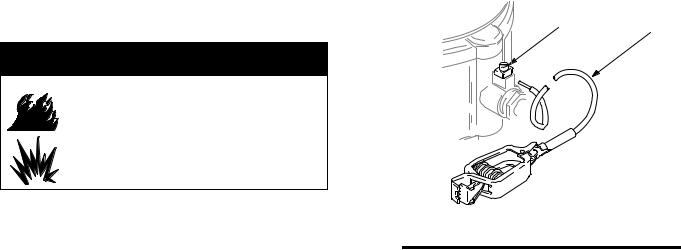
DPump: Attach a ground wire (Y) to the pump’s grounding screw (35) and secure with the screw, as shown in Fig. 1. Connect the clamp end of the ground wire to a true earth ground. Order Part No. 238909 Ground Wire and Clamp.
35 Y
ti1030b
Fig. 1
DAir and fluid hoses: Use only electrically conductive hoses.
DAir compressor: Follow the manufacturer’s recommendations.
DSolvent pails used when flushing: Follow your local code. Use only metal pails, which are conductive. Do not place the pail on a non-conductive surface, such as paper or cardboard, which interrupts the grounding continuity.
DFluid supply container: Follow your local code.
309303 7

Installation
Air Line
 WARNING
A bleed-type master air valve (B) is required in your system to relieve air trapped between this valve and the pump. See Fig. 2. Trapped air can cause the pump to cycle unexpectedly, which could result in serious injury, including splashing in the eyes or on the skin, injury from moving parts, or contamination from hazardous fluids.
1.Install the air line accessories as shown in Fig. 2. Mount these accessories on the wall or on a bracket. Be sure the air line supplying the accessories is electrically conductive.
a.The fluid pressure can be controlled in two ways, either by controlling the air into the pump with the air regulator (F) or the fluid out of the pump with the fluid regulator (H).
b.Locate a bleed-type master air valve (B) close to the pump, to relieve trapped air. See the WARNING at left. Locate another air valve (E) upstream from all air line accessories, to isolate them during cleaning and repair.
c.Install an air line filter (D) to remove harmful contaminants such as dirt, moisture, and oil from the compressed air supply.
2.The air valve does not require lubrication.
3.Install an electrically conductive, flexible air hose
(C) between the accessories and the pump air inlet
(T). Use a minimum 1/4” (6.3 mm) ID air hose. Screw an air line quick disconnect coupler (V) onto the end of the air hose and screw the mating fitting into the pump air inlet snugly. Do not connect the coupler to the fitting yet.
8 309303
 Loading...