


248204
Graco 248204, 249057, 249059, 253056, 257146 User Manual
...
Repair
Displacement Pump
3300 psi (227 bar, 22.7 MPa) Maximum Working Pressure
Model 248204, Series A
Ultrar Max II and Ultimate Mx II 695 and 795
ASM Zip--Sprayt 2700 Plus, 3100 Plus
ASM AllPro Mach 8600 Plus and 11000 Plus
ASM H2700 Plus
Model 255968, Series A
ASM 3600G Plus
310643T
EN
Model 248205, Series A
Ultra Max II and Ultimate Mx II 1095 and 1595
Model 249059, Series A
TexSprayt Mark V
Model 249057, Series A
TexSpray Mark V
Model 277069, Series A
LineLazert IV 3900, R300
Model 277070, Series A
LineLazert IV 5900
Model 253056, Series A
Mark IV
Model 257146, Series A
Ironman 300E and Ironman 500G
Important Safety instructions
Read all warnings and instructions in this manual.
Save these instructions.
8016A
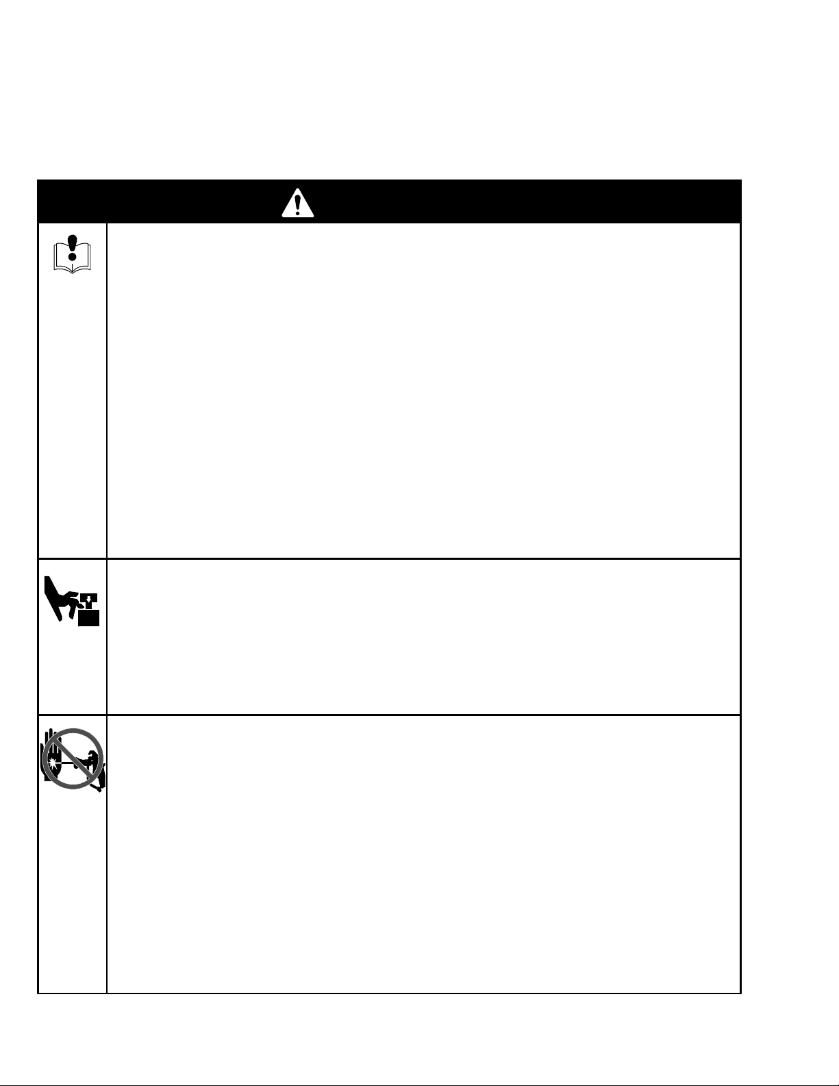
Table of Contents
Warnings 2......................................
Service 3.......................................
Technical Data 15................................
WARNING
EQUIPMENT MISUSE HAZARD
Misuse can cause death or serious injury.
D Do not exceed the maximum working pressure temperature rating of the lowest rated system
component. See Technical Data in all equipment manuals.
D Use fluids and solvents compatible with equipment wetted parts. See Technical Data in all equip-
ment manuals. Read manufacturer fluid and solvent warnings.
D Check equipment daily. Repair or replace worn or damaged parts immediately.
D Do not alter or modify equipment.
D Read all instruction manuals, tags, and labels before operating the equipment.
D Use equipment only for its intended purpose. Call your Graco distributor for information.
Parts, Pump
248204, 255968 16.............................
248205, 249057, 249059, 277070, 257146 17.....
253056 18.....................................
Warranty 20.....................................
D Do not use 1,1,1--trichloroethane, methylene chloride, other halogenated hydrocarbon solvents or
fluids containing such solvents in pressurized aluminum equipment. Such use could result in a
chemical reaction, with the possibility of explosion.
D Comply with all applicable safety regulations.
MOVING PARTS HAZARD
Moving parts can pinch or amputate your fingers.
D Keep clear of moving parts.
D Do not operate equipment with protective guards or covers removed.
D Pressurized equipment can start without warning. Before checking, moving or servicing equipment,
follow the Pressure Relief Procedure on page 3. Disconnect power cord.
SKIN INJECTION HAZARD
High-pressure fluid from gun, hose leaks or ruptured components will pierce skin. This may look like
just cut, but it is a serious injury that can result in amputation. Get immediate surgical treatment.
D Do not point the gun at anyone or at any part of the body.
D Do not put your hand over the spray tip.
D Do not stop or deflect leaks with your hand, body, glove or rag.
D Do not spray without tip guard and trigger guard installed.
D Engage the gun trigger safety when you stop spraying.
D Follow the Pressure Relief Procedure on page 3 if the spray tip clogs and before cleaning,
2 310643
checking or servicing the equipment.

Service
Pressure Relief Procedure
WARNING
PRESSURIZED EQUIPMENT HAZARD
The system pressure must be manually
relieved to prevent the system from
starting or spraying accidentally. To
reduce the risk of an injury from accidental spray
from the gun, splashing fluid, or moving parts,
follow the Pressure Relief Procedure whenever
you:
D areinstructedtorelievethepressure,
D stop spraying,
D check or service any of the system equipment,
D or install or clean the spray nozzle.
1. Engage gun safety latch.
2. Turn ON/OFF switch to OFF.
3. Unplug power cord.
4. Disengage gun safety latch. Hold metal part of gun
against grounded metal pail and trigger gun into
pail to relieve pressure.
To o ls Needed
Vise
12 in. adjustable, open end wrench (2)
Hammer, 20 oz maximum
Small screwdriver
Throat Seal Liquid
Pick or long small screwdriver
Cleaning and Inspecting Parts
1. Clean and inspect parts. Pay particular attention to
the ball seats in the intake valve and piston, which
must have no nicks or wear, and to the inside of
the sleeve and the outside of the piston rod, which
must not be worn or scratched. Replace worn or
damaged parts.
5. Engage gun safety latch.
6. Open any fluid drain valves in system. Leave drain
valve open until ready to dispense again.
Pump Repair Kits
Pump Repair Kit
248204, 255968 248212
253056 287825
248205, 249057, 249059,
257146
248213
WARNING
COMPONENT RUPTURE HAZARD
Never use sharp or pointed tools to
remove sleeve or other components
which could result in pump rupture and
cause serious bodily injury. If the sleeve cannot be
removed easily, return the sleeve and cylinder to
your Graco distributor for removal.
2. Remove and clean the sleeve when you are
repacking the pump.
3310643
Service
Repair When Pump Is Off T h e Sprayer
Disassembling the pump
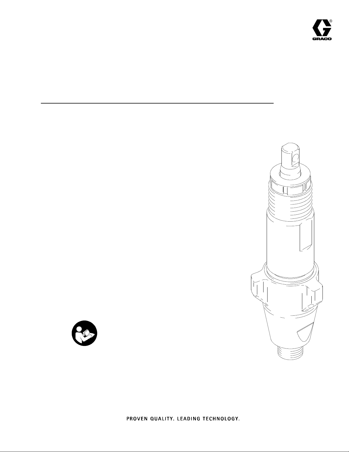
Fig. 1. Remove packing nut (202) and throat adjustment spacer (228).
202
228
ti2332a
Fig. 1
7568A
Fig. 3. Disassemble intake valve. Clean and inspect.
O-ring (227) may require a pick for removal.
227
7570e
Fig. 3
Fig. 4. T ap piston rod out of cylinder with a hammer or
flip over and tap piston rod out against a bench.
Note: Sleeve may come out
of cylinder with piston rod.
Fig. 2. Unscrew intake valve from cylinder.
Fig. 2
7569A
Fig. 4
7571a
Fig. 5. Remove piston rod from sleeve, or remove
sleeve from cylinder. Mark IV: Remove sleeve spacer
(230) from sleeve.
Fig. 5
7572A
4 310643
Service
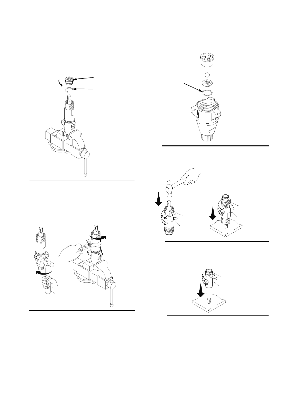
WARNING
COMPONENT RUPTURE HAZARD
Do not clean or wipe the piston valve
threads. Cleaning the piston valve
threads could destroy the special sealing
patch and cause the piston valve to come loose
during operation, causing pump bursting and
possible serious bodily injury.
Fig. 6. Unscrew piston valve from piston rod. Clean
and inspect parts. The piston has a special thread
locking/sealing patch. Do not remove the patch. The
patch allows four disassembly/assembly procedures
before it is necessary to apply Loctiter to the threads.
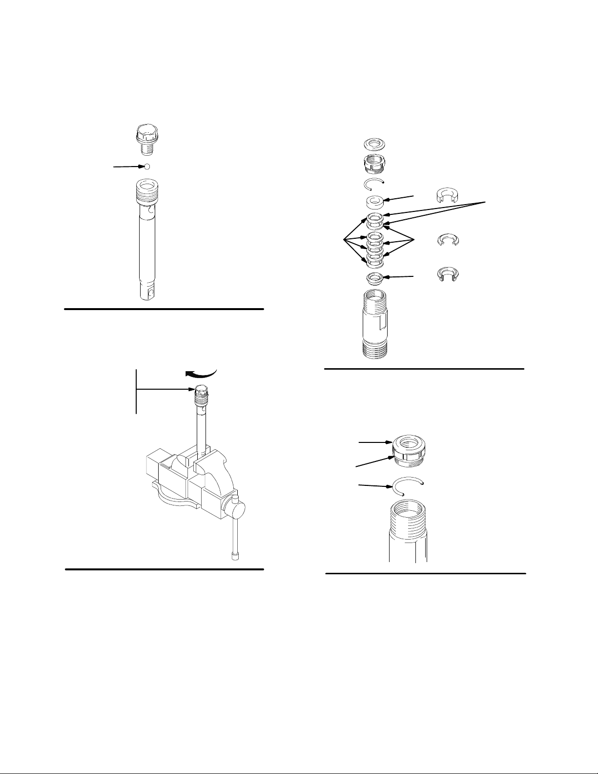
Fig. 8. Remove throat packings and glands from cylinder. Discard throat packings and glands.
Not
used on
248204
253056
255968
Fig. 6
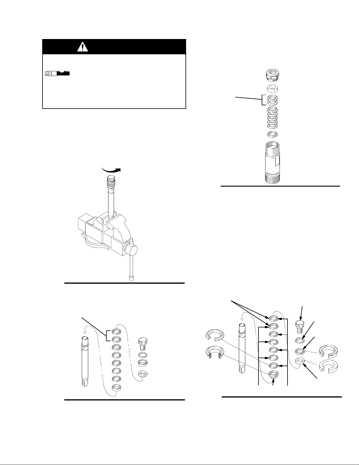
Fig. 7. Remove packings and glands from piston rod.
Not
used on
248204
253056
255968
7576A
Fig. 8
Assembling the pump
Fig. 9. Soak all leather packings in SAE 30W oil for 1
hour minimum prior to assembly. Stack male gland
(204) on piston rod. Alternately stack UHMWPE (208)
and leather (218) packings (note orientation) on piston
rod. Install female gland (217). Install piston wiper
(216) (note orientation) and backup washer (229) on
piston valve (210). The special sealing patch on piston
valve threads is good for four repackings. Use Loctiter
on piston valve threads after four repackings.
Not
used on
248204
253056
255968
210
7573B
229
216
Fig. 7
ti3940b
Fig. 9
204
218 208
217
7574d
5310643
Service
Fig. 10. Install ball (206) in piston rod. If Loctiter is applied to piston valve threads, ensure that none gets on
ball.
206
Fig. 10
7575A
Fig. 11. Tighten piston valve to piston rod as specified:
Fig. 12. Soak all leather packings in SAE 30W oil for 1
hour minimum prior to assembly. Place male gland
(204) in cylinder. Alternately stack UHMWPE (203) and
leather packings (223) (note orientation). Place female
gland (224) in top of cylinder. Seat packings.
224
Not
used on
248204
253056
203
223
255968
204
Torque to 27 +/-- 3 ft-lb
(248204, 253056, 255968,
277069)
Torque to 55 +/--3 ft-lb
(248205, 249057, 249059,
277070, 257146)
Fig. 11
7576A
Fig. 12
7573f
Fig. 13. Install seal (201) into packing nut (202). Install
throat adjustment spacer (228) onto packing nut.
Loosely install packing nut into cylinder.
201
202
228
Fig. 13
7581A
6 310643
 Loading...