


Instructions–Parts List
STAINLESS STEEL, |
|
|
WATERBASE-COMPATIBLE, HIGH PRESSURE |
308647P |
|
Fluid Pressure Regulators |
||
EN |
For precise downstream pressure and flow control.
Important Safety Instructions
Read all warnings and instructions in this manual.
Save these instructions.
See page 2 for List of Models and Table of Contents.
06290
|
06288 |
Model 238890, |
Model 238894 |
238892 |
(air-operated) |
(spring-operated) |
|
U.S. Patent No. 4942899
06540A
Table of Contents
List of Models . . . . . . . . . . . . . . . . . . . . . . . . . . . . . . . . . . 2
Warnings . . . . . . . . . . . . . . . . . . . . . . . . . . . . . . . . . . . . . . 3
Installation . . . . . . . . . . . . . . . . . . . . . . . . . . . . . . . . . . . . . 6
Operation . . . . . . . . . . . . . . . . . . . . . . . . . . . . . . . . . . . . . 8
Troubleshooting . . . . . . . . . . . . . . . . . . . . . . . . . . . . . . . 10
Service . . . . . . . . . . . . . . . . . . . . . . . . . . . . . . . . . . . . . . 11
Parts
238889, 238890, 238891, and 238892 . . . . . . . . . . 14
238893, 238894, 248090, and 255072 . . . . . . . . . . 16
244734 . . . . . . . . . . . . . . . . . . . . . . . . . . . . . . . . . . . . . 18
Technical Data . . . . . . . . . . . . . . . . . . . . . . . . . . . . . . . . 20
Performance Chart . . . . . . . . . . . . . . . . . . . . . . . . . . . . 21
Dimensional Drawings . . . . . . . . . . . . . . . . . . . . . . . . . 23
Graco Standard Warranty . . . . . . . . . . . . . . . . . . . . . . 24
Graco Information . . . . . . . . . . . . . . . . . . . . . . . . . . . . . 24
List of Models
Spring-Operated Models
Part No. |
Description |
Range |
Maximum Fluid |
Regulated Fluid |
|
Inlet Pressure |
Outlet Pressure |
||||
|
|
|
|||
|
|
|
|
|
|
238889 |
with EZ Flush gauge port plug |
Medium |
6000 psi |
500–3000 psi |
|
|
|
|
(41 MPa, 414 bar) |
(3.4–21 MPa, 34–207 bar) |
|
238890 |
with fluid pressure gauge |
Medium |
6000 psi |
500–3000 psi |
|
|
|
|
(41 MPa, 414 bar) |
(3.4–21 MPa, 34–207 bar) |
|
238891 |
with EZ Flush gauge port plug |
High |
6000 psi |
3000–5000 psi |
|
(41 MPa, 414 bar) |
(21–34 MPa, 207–345 bar) |
||||
|
|
|
|||
|
|
|
|
|
|
238892 |
with fluid pressure gauge |
High |
6000 psi |
3000–5000 psi |
|
(41 MPa, 414 bar) |
(21–34 MPa, 207–345 bar) |
||||
|
|
|
|||
|
|
|
|
|
Air-Operated Models
Part No. |
Description |
Range |
Maximum Inbound |
Maximum Fluid |
Regulated Fluid |
|
Air Pressure |
Inlet Pressure |
Outlet Pressure |
||||
|
|
|
||||
|
|
|
|
|
|
|
238893 |
with EZ Flush gauge |
Full |
100 psi |
6000 psi |
500–4000 psi |
|
port plug |
(0.7 MPa, 7 bar) |
(41 MPa, 414 bar) |
(3.4–28 MPa, 34–276 bar) |
|||
|
|
|||||
|
|
|
|
|
|
|
238894 |
with fluid pressure |
Full |
100 psi |
6000 psi |
500–4000 psi |
|
gauge |
(0.7 MPa, 7 bar) |
(41 MPa, 414 bar) |
(3.4–28 MPa, 34–276 bar) |
|||
|
|
|||||
|
|
|
|
|
|
|
244734 |
with EZ Flush gauge |
Full |
100 psi |
6000 psi |
500–4000 psi |
|
port plug |
(0.7 MPa, 7 bar) |
(41 MPa, 414 bar) |
(3.4–28 MPa, 34–276 bar) |
|||
|
|
|||||
|
|
|
|
|
|
|
248090 |
with fluid pressure |
Full |
100 psi |
6000 psi |
500–4000 psi |
|
gauge (LASD) |
(0.7 MPa, 7 bar) |
(41 MPa, 414 bar) |
(3.4–28 MPa, 34–276 bar) |
|||
|
|
|||||
|
|
|
|
|
|
|
255072 |
high resolution with |
Full |
100 psi |
6000 psi |
500–2700 psi |
|
fluid pressure gauge |
(0.7 MPa, 7 bar) |
(41 MPa, 414 bar) |
(3.4–19 MPa, 34–190 bar) |
|||
|
|
|||||
|
|
|
|
|
|
2 308647

|
Symbols |
Warning Symbol |
Caution Symbol |
WARNING |
CAUTION |
This symbol alerts you to the possibility of serious injury or death if you do not follow the instructions.
This symbol alerts you to the possibility of damage to or destruction of equipment if you do not follow the instructions.
 WARNING
EQUIPMENT MISUSE HAZARD
Equipment misuse can cause the equipment to rupture or malfunction and result in serious injury.
INSTRUCTIONS
DThis equipment is for professional use only.
DRead all instruction manuals, tags, and labels before operating the equipment.
DUse the equipment only for its intended purpose. If you are not sure, call your Graco distributor.
DDo not alter or modify this equipment. Use only genuine Graco parts and accessories.
DCheck equipment daily. Repair or replace worn or damaged parts immediately.
DDo not kink or over bend the hose or use the hose to pull equipment.
DDo not exceed the maximum working pressure of the lowest rated component in your system. Do not exceed 6000 psi (41 MPa, 414 bar) maximum fluid inlet pressure of the regulator or the maximum working pressure of the lowest-rated component in your system.
DUse fluids and solvents which are compatible with the equipment wetted parts. Refer to the Technical Data section of all equipment manuals. Read the fluid and solvent manufacturer’s warnings.
DAlways wear protective eyewear, gloves, clothing, and respirator as recommended by the fluid and solvent manufacturer.
DComply with all applicable local, state, and national fire, electrical, and safety regulations.
308647 3

 WARNING
SKIN INJECTION HAZARD
Spray from the gun, leaks, or ruptured components can inject fluid into your body and cause extremely serious injury, including the need for amputation. Fluid splashed in the eyes or on the skin can also cause serious injury.
DFluid injected into the skin might look like just a cut, but it is a serious injury. Get immediate surgical treatment.
DDo not point the gun at anyone or at any part of the body.
DDo not put your hand or fingers over the spray gun tip or extruder gun tip.
DDo not stop or deflect leaks with your hand, body, glove or rag.
DAlways have the tip guard and the trigger guard on the gun when spraying.
DCheck the gun diffuser operation weekly. Refer to the gun manual.
DBe sure the gun trigger safety operates before spraying.
DLock the gun trigger safety when you stop dispensing.
DFollow the Pressure Relief Procedure on page 7 if the spray tip clogs and before cleaning, checking, or servicing the equipment.
DTighten all fluid connections before operating the equipment.
DCheck the hoses, tubes, and couplings daily. Replace worn or damaged parts immediately. Do not repair high pressure couplings; you must replace the entire hose.
DFluid hoses must have spring guards on both ends to help protect them from rupture caused by kinks or bends near the couplings.
HALOGENATED HYDROCARBON HAZARD
Never use 1,1,1–trichloroethane, methylene chloride, other halogenated hydrocarbon solvents, or fluids containing such solvents in these regulators. In the unlikely event that there is a diaphragm failure and the vent hole in the aluminum spring cap is plugged, a serious chemical reaction could occur, with the possibility of explosion, which could cause death, serious injury, and/or substantial property damage.
Consult your fluid suppliers to ensure that the fluids used are compatible with aluminum parts.
TOXIC FLUID HAZARD
Graco does not manufacture or supply the reactive chemical components that may be used in this equipment and is not responsible for injury or property loss, damage, expense or claims (direct or consequential) that arise from the use of such chemical components.
4 308647

Notes
308647 5

Installation
Multiple Circulating Spray Station
Key
AAir regulator
BBleed-type master air valve
CPump
DFluid filter and drain valve
EMain fluid supply line
FGun fluid supply line
GFluid regulator
with fluid pressure gauge (H)
HFluid pressure gauge
JAir-assisted airless spray gun
KBack pressure valve
LFluid return line
MMain circulating line
NFluid supply container
P Drain valve
M E 
C
A B
N D
 WARNING
Do not use PTFE tape on pipe threads. Such use could cause a hazardous condition due to loss of grounding continuity. Also, if pieces of the tape break off, the function of the regulator could be affected.
Fig. 1
F
K
J J
L
K
G |
G |
H |
H |
|
06461 |
P |
P |
Single Direct Spray Station
C
A B
J 
G
H |
|
F |
|
|
|
D |
P |
06462 |
|
|
The installations shown in Fig. 1 are only a guide for selecting and installing a circulating or direct system; they are not actual system designs. Contact your Graco distributor for assistance in designing a system to suit your needs.
NOTE: Before you install the regulator, thoroughly flush the system to remove metal chips and other contaminants. A fluid filter (D) of 60-mesh or finer should always be installed upstream of the regulator.
Connections
Install the fluid regulator (G) in the spray gun fluid supply line (F), as shown in the typical installation drawings on this page. Connect only one spray gun or dispensing valve to each fluid regulator.
Apply pipe sealant to the male pipe threads, and connect the fluid supply line (F) to the fluid regulator’s 3/8 npt(f) inlet. Connect the line from the gun (J) to the fluid regulator’s 3/8 npt(f) outlet. Install the gauge or plug into the 1/4 npt(f) gauge port.
Make sure the direction of fluid flow agrees with the IN and OUT markings on the regulator body.
Flush the System
The regulator was tested in lightweight oil. Flush the entire system with a solvent compatible with the fluid being dispensed. Then test the system.
Mounting Bracket
A Mounting Bracket is available for mounting the regulator. Order Part 222515 for the bracket and mounting hardware.
6 308647
Installation
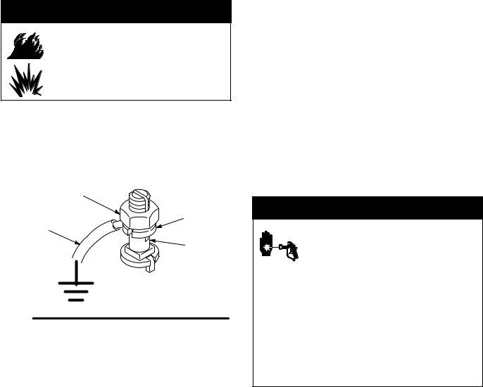
Grounding the System
 WARNING
FIRE AND EXPLOSION HAZARD
Before operating the fluid pressure regulator, ground the system as explained below.
Pump: Use a ground wire and clamp. Loosen the grounding lug locknut (W) and washer (X). Insert one end of a 1.5 mm@ (12 ga) minimum ground wire (Y) into the slot in lug (Z) and tighten the locknut securely. Connect the other end of the wire to a true earth ground. Order Part 237569 Ground Wire and Clamp.
W
X
Y
Z
0864
Fig. 2
Air and fluid hoses: Use only electrically conductive hoses.
Heaters, if used: See the heater instruction manual.
Air compressor: Follow manufacturer’s recommendations.
Spray gun: Ground through connection to a properly grounded fluid hose and pump.
Fluid supply container: Follow your local code.
Object being sprayed: Follow your local code.
Solvent pails used when flushing: Follow your local code. Use only metal pails, which are conductive, placed on a grounded surface. Do not place the pail on a nonconductive surface, such as paper or cardboard, which interrupts the grounding continuity.
To maintain grounding continuity when flushing or relieving pressure, hold a metal part of the spray gun firmly to the side of a grounded metal pail, then trigger the gun.
Pressure Relief Procedure
 WARNING
SKIN INJECTION HAZARD
The system pressure must be manually relieved to prevent the system from starting or spraying accidentally. Fluid
under high pressure can be injected through the skin and cause serious injury. To reduce the risk of an injury from injection, splashing fluid, or moving parts, follow the Pressure Relief Procedure whenever you
DAre instructed to relieve the pressure
DStop spraying
DCheck or service any of the system equipment
DInstall or clean the spray tips
308647 7

Operation
Adjusting the System Pressure
 CAUTION
DThe new system must be cleaned and tested thoroughly before admitting fluid to the regulator to avoid contaminants clogging or damaging the regulator.
DAlways use the lowest possible air and fluid pressures for your application. High pressures can cause premature spray tip, regulator, and pump wear.
NOTES:
DThe fluid pressure regulator controls pressure downstream from its outlet.
DIf you are using an accessory fluid pressure gauge (H in Fig. 1), relieve the spray gun line pressure after you reduce the regulator pressure to ensure a correct gauge reading.
1.Make a note of the proper way to adjust pressure, from the following descriptions:
D On a spring-operated regulator, turn the adjusting screw (10) counterclockwise to decrease pressure and clockwise to increase pressure to the spray gun or extruder gun.
D On an air-operated regulator, increase supply air pressure to increase fluid pressure. Decrease supply air pressure to decrease fluid pressure. Supply air up to 100 psi (0.7 MPa, 7 bar). See the chart on page 20 for air versus fluid pressure.
NOTE: Air-operated regulator Models 238893 and 238894 are provided with an air supply regulator (31) to control the fluid set pressure. For increased sensitivity in pressure set point performance, an alternative air regulator, such as Part 206197, may be used. This alternative air regulator uses a sensitive diaphragm design to maintain a higher, more accurate air pressure setting.
2.Adjust the pump air pressure and fluid regulator for the desired spray pattern. Use the lowest possible air and fluid pressures for your application. For optimum performance, the inbound fluid pressure should be at least 500 psi (3.4 MPa, 34 bar) above the regulated fluid pressure.
NOTE: Do not exceed a 2000 psi (14 MPa,
138 bar) pressure drop between the regulator inlet and outlet. Excessive pressure drop will cause premature regulator component wear.
For example: With 3500 psi (24.5 MPa, 245 bar) to the regulator, the minimum regulated outlet pressure would be 1500 psi (10.5 MPa, 105 bar).
3.In a circulating system, also adjust the back pressure valve (K).
4.Record all the settings for future reference.
Cleaning the Regulator
Do not allow fluid to settle in the system.
Flush the regulator whenever the rest of the system is flushed (see page 9). Before you flush the system, follow the Pressure Relief Procedure on page 7, then completely decrease the regulated fluid pressure. See step 1 in Adjusting the System Pressure, at left.
Before you remove the regulator for thorough cleaning and inspection, follow the Pressure Relief Procedure on page 7. Then remove the regulator, clean it, and inspect all parts.
8 308647
 Loading...