


INSTRUCTIONS |
309317 |
|
Rev. B |
This manual contains important warnings and information.
READ AND KEEP FOR REFERENCE.
INSTRUCTIONS
US Patent Pending
HVLP–Turbine Guns
10 psi (0.07 MPa, .7 bar) Maximum Inlet Air Pressure 50 psi (0.35 MPa, 3.5 bar) Maximum Inlet Fluid Pressure
Related Manuals
309205 – HVLP–Turbine Gun for maintenance and service instructions
309243 – HVLP Turbine
309244 – HVLP Compressor/Cart
T10746
Cup Feed |
Remote Pressure Feed |
|
|
||
Includes 1-quart (1 liter) cup |
Model 244115, without fluid set |
|
Model 244113, without fluid set |
||
Model 244118, with # 3 fluid set |
||
Model 244117, with # 3 fluid set |
||
|
GRACO INC. P.O. BOX 1441 MINNEAPOLIS, MN 55440–1441
ECOPYRIGHT 2001, GRACO INC. Graco Inc. is registered to I.S. EN ISO 9001

Table of Contents
Symbols . . . . . . . . . . . . . . . . . . . . . . . . . . . . . . . . . . . . . . 2
Warnings . . . . . . . . . . . . . . . . . . . . . . . . . . . . . . . . . . . . . . 3
Component Identification . . . . . . . . . . . . . . . . . . . . . . . . 4
Setup . . . . . . . . . . . . . . . . . . . . . . . . . . . . . . . . . . . . . . . . . 7
Spray . . . . . . . . . . . . . . . . . . . . . . . . . . . . . . . . . . . . . . . . . 7
Shutdown . . . . . . . . . . . . . . . . . . . . . . . . . . . . . . . . . . . . . 8
Parts List . . . . . . . . . . . . . . . . . . . . . . . . . . . . . . . . . . . . . 15
Parts Drawing . . . . . . . . . . . . . . . . . . . . . . . . . . . . . . . . . 14
Technical Data . . . . . . . . . . . . . . . . . . . . . . . . . . . . . . . . 16
Graco Phone Number . . . . . . . . . . . . . . . . . . . . NO TAG
Warning Symbol
 WARNING
This symbol alerts you to the possibility of serious injury or death if you do not follow instructions.
Caution Symbol
 CAUTION
This symbol alerts you to the possibility of damage to or destruction of equipment if you do not follow instructions.
You will need:
Cleaning fluids: a compatible solvent; water–based paint also requires soap and water.
Suggested proper clothing:
• Safety glasses |
• Sturdy boots or shoes |
• Respirator |
• Gloves |
2 309317
Fire and explosion hazard: Solvent and paint fumes can ignite or explode.
DSprayers generate sparks. Keep sprayer at least 20 feet (6 m) from explosive vapors.
DUse in an extremely well ventilated area.
DEliminate all ignition sources; such as pilot lights,
cigarettes and static arcs from plastic drop cloths.
Do not plug or unplug power cords or turn lights on or off in spray area. DGround Sprayer, object being sprayed, paint and
solvent pails. DDo not use 1,1,1-trichloroethane, methylene chlo-
ride, other halogenated hydrocarbon solvents or fluids containing such solvents in pressurized aluminum equipment. Such use could result in a chemical reaction, with the possibility of explosion.
Equipment Misuse Hazard: Equipment misuse can cause the equipment to rupture or malfunction and result in serious injury.
DBefore operating equipment, read all instruction manuals, tags, and labels.
DCheck equipment daily. Repair or replace worn or damaged parts immediately.
DDo not exceed maximum working pressure (MWPR) of the lowest–rated system component
DUse fluids and solvents that are compatible with the equipment wetted parts. See Specifications on page for this information.
DWear hearing protection when operating this equipment. DDo not “blow back” fluid; this is not an air spray system
DFollow Pressure Relief before cleaning, checking or servicing the equipment.
TOXIC FLUID HAZARD: Hazardous fluid or toxic fumes can cause serious injury or death if splashed in eyes or on skin, inhaled, or swallowed.
DKnow specific hazards of fluid you are using and take protective measures as
recommended by the fluid and solvent manufacturer.
309317 3

Component Identification
Air flow control – Adjusts TOTAL air flow to spray gun
Pattern Adjustment Knob – Adjusts pattern from fan to round
Air cap/retaining ring – Adjusts
fan direction
Fluid flow/Pattern size control – Adjusts fluid volume
Air inlet
EasyGlidet Trigger
Cup
Duckbill check valve
Swivel tube and strainer
4 309317

PRESSURE RELIEF – Follow this procedure when cleaning, repairing or shuting down sprayer
For Cup Guns
Follow these |
|
|
|
instructions whenever |
1. Turn off turbine. |
2. Unlatch cup |
|
you stop spraying. |
|||
|
|
For Pressure Feed Guns
Follow these instructions whenever you stop spraying.
1. Turn off air supply to the pot.
A  A
A
2. Open pressure relief (A) on |
2 quart |
pot until pressure is completely |
|
relieved. Close relief. |
|
8069A |
02882 |
TIP SELECTION
A Tip consists of a fluid nozzle, and fluid needle. Use the following chart for recommendations.
Fluid Set |
Tip Size |
Fluid Usage |
|
|
|
|
|
#2 |
0.8 mm |
Ink, dye and non–wiping stain. |
|
244123 |
(0.032 in) |
|
|
|
|
|
|
#3 |
1.3 mm |
Water base lacquer, urethane, varnish, stain, and automotive finish. |
|
244124 |
(0.051 in) |
|
|
|
|
|
|
#4 |
1.8 mm |
Lacquer, urethane, varnish, stain, primer, enamel and epoxy. |
|
(0.071 in) |
|
||
244125 |
|
||
|
|
|
|
|
|
|
|
#5 |
2.2 mm |
Lacquer, urethane, varnish, stain, primer, enamel, epoxy and |
|
244126 |
(0.087 in) |
higher output industrial finishes. |
|
|
|
|
|
#6 |
2.5 mm |
Latex, multi–spec, oil wall paint, industrial finishes, buty- |
|
244127 |
(0.098 in) |
rate, and nitrate dope. |
|
|
|
|
|
Installing the Fluid Set
 CAUTION
Trigger the gun whenever you tighten or remove the nozzle. This keeps the needle seat away from the nozzle seating surface and prevents the seat from being scratched.
309317 5
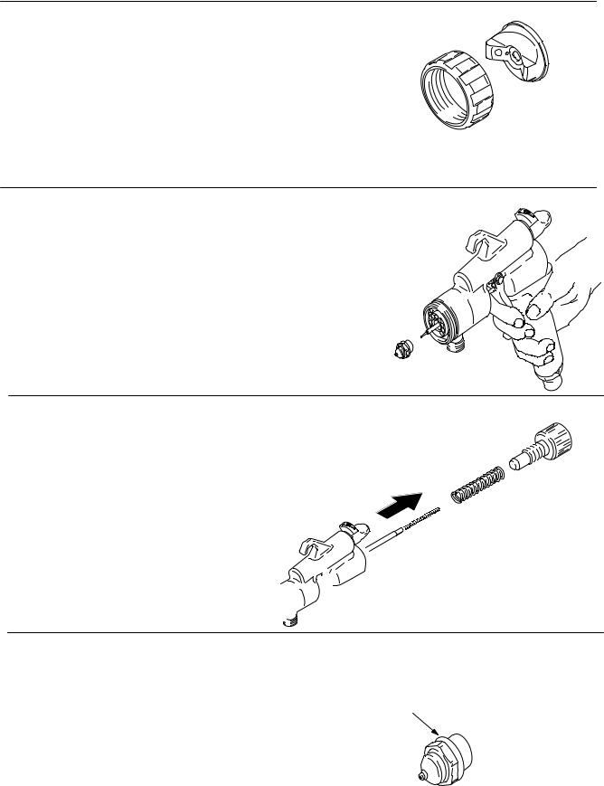
1.Use your hand to loosen and remove the air cap retaining ring and air cap housing.
2.Test spray pattern and atomization while holding gun about 6 to inches (150 to 200 mm) from test piece.
.
3. While triggering the gun, use your hand to loosen and remove the nozzle.
4. Use your hand to loosen and remove the fluid knob assembly and compression ring from the back of the gun and remove the old needle.
5. Insert the needle assembly in the back of the gun. Reassemble nozzle, air cap housing and air cap retaining ring. Hand tighten.
A
Note: Nozzle should always have an o–ring (A).
6 309317
 Loading...