


 Loading...
Graco 249691, 249690, 255113, 255110, 255114 User Manual
...Repair
FinishPro™ 390/395
Airless/Air-Assisted Sprayer
311911C
- For the application of architectural paints and coatings -
Maximum Fluid Working Pressure: 3300 psi (227 bar, 22.7 MPa)
Maximum Air Working Pressure: 35 psi (2.4 bar, 0.24 MPa)
IMPORTANT SAFETY INSTRUCTIONS!
Read all warnings and instructions. Save these instructions. Contact Graco Customer Service, your local Graco distributor or our website: www.graco.com, to obtain a manual in your language.
Models: |
|
|
FinishPro 395 |
|
|
|
|
Region |
FinishPro 390 |
FinishPro 395 |
|
|
|
|
|
|
|
|
|
US |
249690 |
249691 |
|
|
|
|
|
Europe CEE 7/7 |
255110 |
255111 |
|
|
|
|
|
Europe Multi Cord |
255112 |
255113 |
|
|
|
|
|
UK |
255114 |
255115 |
|
|
|
|
|
Asia/Australia |
255116 |
255117 |
|
|
|
|
|
Related Manuals:
311905 |
ti9026a |
|
FinishPro 390
309250
311937
312100
ti9019a
Graco Inc. P.O. Box 1441 Minneapolis, MN 55440-1441
Copyright 2007, Graco Inc. is registered to I.S. EN ISO 9001

Warning
Warning
The following warnings are for the setup, use, grounding, maintenance and repair of this equipment. The exclamation point symbol alerts you to a general warning and the hazard symbol refers to procedure-specific risks. Refer back to these warnings. Additional, product-specific warnings may be found throughout the body of this manual where applicable.
 WARNING
FIRE AND EXPLOSION HAZARD
Flammable fumes, such as solvent and paint fumes, in work area can ignite or explode. To help prevent fire and explosion:
• Use equipment only in well ventilated area.
• Eliminate all ignition sources; such as pilot lights, cigarettes, portable electric lamps, and plastic drop cloths (potential static arc).
• Sprayer generates sparks. When flammable liquid is used in or near the sprayer or for flushing or cleaning, keep sprayer at least 20 feet (6 m) away from explosive vapors.
•Keep work area free of debris, including solvent, rags and gasoline.
•Do not plug or unplug power cords or turn lights on or off when flammable fumes are present.
•Ground equipment and conductive objects in work area. Read Grounding instructions.
•If there is static sparking or you feel a shock, stop operation immediately. Do not use equipment until you identify and correct the problem.
•Keep a working fire extinguisher in the work area.
ELECTRIC SHOCK HAZARD
Improper grounding, setup, or usage of the system can cause electric shock.
•Turn off and disconnect power cord before servicing equipment.
•Use only grounded electrical outlets.
•Use only 3-wire extension cords.
•Ensure ground prongs are intact on sprayer and extension cords.
•Do not expose to rain. Store indoors.
SKIN INJECTION HAZARD
High-pressure fluid from gun, hose leaks, or ruptured components will pierce skin. This may look like just a cut, but it is a serious injury that can result in amputation. Get immediate surgical treatment.
• Do not point gun at anyone or at any part of the body.
•Do not put your hand over the spray tip.
•Do not stop or deflect leaks with your hand, body, glove, or rag.
•Engage trigger lock when not spraying.
•Follow Pressure Relief Procedure in this manual, when you stop spraying and before cleaning, checking, or servicing equipment.
2 |
311911C |
Warning
WARNING
EQUIPMENT MISUSE HAZARD
Misuse can cause death or serious injury.
•Do not exceed the maximum working pressure or temperature rating of the lowest rated system component. Read Technical Data in all equipment manuals.
•Use fluids and solvents that are compatible with equipment wetted parts. Read Technical Data in all equipment manuals. Read fluid and solvent manufacturer’s warnings. For complete information about your material, request MSDS from distributor or retailer.
•Check equipment daily. Repair or replace worn or damaged parts immediately with genuine Graco replacement parts only.
•Do not alter or modify equipment.
•Use equipment only for its intended purpose. Call your Graco distributor for information.
•Route hoses and cables away from traffic areas, sharp edges, moving parts, and hot surfaces.
•Do not kink or overbend hoses or use hoses to pull equipment.
•Keep children and animals away from work area.
•Comply with all applicable safety regulations.
•Keep children and animals away from work area.
•Do not operate the unity when fatigued or under the influence of drugs or alcohol.
PRESSURIZED ALUMINUM PARTS HAZARD
Do not use 1,1,1-trichloroethane, methylene chloride, other halogenated hydrocarbon solvents or fluids containing such solvents in pressurized aluminum equipment. Such use can cause serious chemical reaction and equipment rupture, and result in death, serious injury, and property damage.
BURN HAZARD
Equipment surfaces can become very hot during operation. To avoid severe burns, do not touch hot equipment. Wait until equipment has cooled completely.
MOVING PARTS HAZARD
Moving parts can pinch or amputate fingers and other body parts.
•Keep clear of moving parts.
•Do not operate equipment with protective guards or covers removed.
•Pressurized equipment can start without warning. Before checking, moving, or servicing equipment, follow the Pressure Relief Procedure in this manual. Disconnect power or air supply.
TOXIC FLUID OR FUMES HAZARD
Toxic fluids or fumes can cause serious injury or death if splashed in the eyes or on skin, inhaled, or swallowed.
•Read MSDS’s to know the specific hazards of the fluids you are using.
•Store hazardous fluid in approved containers, and dispose of it according to applicable guidelines.
PERSONAL PROTECTIVE EQUIPMENT
You must wear appropriate protective equipment when operating, servicing, or when in the operating area of the equipment to help protect you from serious injury, including eye injury, inhalation of toxic fumes, burns, and hearing loss. This equipment includes but is not limited to:
•Protective eye wear
•Clothing and respirator as recommended by the fluid and solvent manufacturer
•Gloves
•Hearing protection
311911C |
3 |

Component Identification
Component Identification
FinishPro 390 |
10 |
21 |
9 |
8 |
|
|
11
|
|
|
6 |
1 |
|
|
17 |
|
|
18 |
|
|
|
|
|
|
|
4 |
|
|
2 |
3 |
|
|
|
|
|
|
|
20 |
ti9018a |
|
|
19 |
|
|
|
|
FinishPro 395
10
7
15
12
17
5  18
18

14 16
ti9021a |
1 |
|
19 20
 13
13
7
 12
12
 5
5
9
8
 4
4
 6
6
 11
11
 3
3
 2
2
4 |
311911C |
Component Identification
Component Identification
Item |
Component |
|
|
|
|
1 |
Prime/Drain Tube/Hose |
|
|
2 |
Air Hose Connection |
|
|
3 |
Prime/Spray Valve |
|
|
4 |
Fluid Outlet |
|
|
5 |
Air/Fluid Supply Hose |
|
|
6 |
Displacement Pump |
|
|
7 |
Gun (see manual) |
|
|
8 |
Filter Manifold |
|
|
9 |
Fluid Pressure Control |
|
|
10 |
Power/Function Selector |
|
|
11 |
Suction Tube |
|
|
12 |
Gun Air Regulator |
|
|
13 |
Direct Immersion Tube (FinishPro 390 model only) |
|
|
14 |
Sprayer Air Pressure Regulator (FinishPro 395 model only) |
|
|
15 |
Digital Display (FinishPro 395 model only) |
|
|
16 |
Air Pressure Gauge (FinishPro 395 model only) |
|
|
17 |
Gun Filter |
|
|
18 |
High Pressure Paint Swivel |
|
|
19 |
Hose T-clip |
|
|
20 |
Flex Coil Air Hose |
|
|
21 |
Fluid Pressure Gage (FinishPro 390 model only) |
|
|
311911C |
5 |
Installation
Installation
Grounding and Electric
Requirements
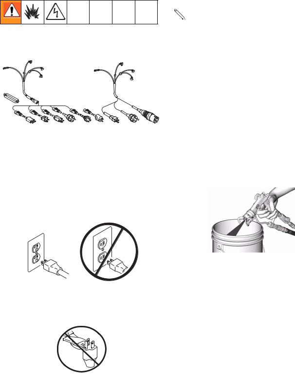
Recommended extension cords for use with this sprayer:
•3-wire, 12 AWG (2.5 mm2) minimum, 300 ft. (90 m) maximum length.
The sprayer cord includes a grounding wire with an appropriate grounding contact.
ti9590a
The sprayer requires:
110-120 Vac Sprayers: 100-120 Vac, 50/60 Hz, 15A, 1 phase, circuit with a grounding receptacle.
230 Vac Sprayers: 230 Vac, 50/60 Hz, 10A, 1 phase, circuit with a grounding receptacle.
Never use an outlet that is not grounded or an adapter.
Smaller gauge or longer extension cords may 
 reduce sprayer performance.
Spray gun: ground through connection to a properly grounded fluid hose and pump.
Fluid supply container: follow local code.
Solvent and Oil-based fluids: follow local code. Use only conductive metal pails placed on a grounded surface such as concrete. Do not place the pail on a nonconductive surface such as paper or cardboard, which interrupts grounding continuity.
Grounding the metal pail: connect a ground wire to the pail by clamping one end to pail and other end to ground such as a water pipe.
To maintain grounding continuity when flushing or relieving pressure: hold metal part of the spray gun firmly to the side of a grounded metal pail, then trigger the gun.
ti9270a
ti5573a
Do not use the sprayer if the electrical cord has a damaged ground contact. Only use an extension cord with an undamaged ground contact.
ti4297a
ti4297a
6 |
311911C |

|
|
|
|
|
|
|
|
|
|
Pressure Relief Procedure |
Pressure Relief Procedure |
General Repair Information |
|||||||||
|
|
|
|
|
|
|
|
|
|
|
|
|
|
|
|
|
|
|
|
|
|
|
|
|
|
|
|
|
|
|
|
|
Follow this Pressure Relief Procedure whenever you are instructed to relieve pressure, stop spraying, check or service equipment or install or clean spray tip.
1.Set function selection switch to OFF and unplug sprayer.
ti8798a
2.Turn pressure to lowest setting.
3.Hold gun against side of grounded metal flushing pail. Trigger gun to relieve pressure.
ti9270a
Flammable materials spilled on hot, bare, motor could cause fire or explosion. To reduce risk of burns, fire or explosion, do not operate sprayer with cover removed.
•Keep all screws, nuts, washers, gaskets, and electrical fittings removed during repair procedures. These parts usually are not provided with replacement kits.
•Test repairs after problems are corrected. If sprayer does not operate properly, review repair procedure to verify you did it correctly. See Troubleshooting, page 8.
•Overspray may build up in the air passages. Remove any overspray and residue from air passages and openings in the enclosures whenever you service sprayer.
•Do not operate sprayer without motor shroud in place. Replace if damaged. Motor shroud directs cooling air around motor to prevent overheating and insulates control board from accidental electric shock.
4. Turn prime valve down.
ti2719a
If you suspect the spray tip or hose is clogged or that pressure has not been fully relieved after following the steps above, VERY SLOWLY loosen tip guard retaining nut or hose end coupling to relieve pressure gradually, then loosen completely. Clear hose or tip obstruction.
5.Engage trigger safety lock on gun if unit is being shut down or left unattended.
To reduce risk of serious injury, including electric shock:
•Do not touch moving or electric parts with fingers or tools while testing repair.
•Unplug sprayer when power is not required for testing.
•Install all covers, gaskets, screws and washers before you operate sprayer.
CAUTION
•Do not run sprayer dry for more than 30 seconds. Doing so could damage pump packings.
•Protect the internal drive parts of this sprayer from water. Openings in the cover allow for air cooling of the mechanical parts and electronics inside. If water gets in these openings, the sprayer could malfunction or be permanently damaged.
•Prevent pump corrosion and damage from freezing. Never leave water or water-base paint in sprayer in cold weather. Freezing fluids can seriously damage sprayer. Store sprayer with Pump Armor to protect sprayer during storage.
•Do not allow material to dry on gun air cap. Poor spray finish could result.
311911C |
7 |

Troubleshooting
Troubleshooting
|
|
|
|
|
|
|
|
|
|
|
|
|
|
|
|
|
|
|
|
|
|
|
|
|
|
|
|
|
|
|
|
|
|
|
|
|
|
|
|
|
|
|
|
Problem |
|
|
|
|
What To Check |
What To Do |
|||||
|
|
|
|
|
(If check is OK, go to next check) |
(When check is not OK, refer to this column) |
|||||||
|
|
|
|
|
|
|
|
|
|||||
|
|
|
|
|
|
|
|
||||||
Sprayer Won’t Operate |
|
|
|
|
|
|
|
||||||
|
|
|
|
||||||||||
|
|
|
|
|
|
|
|
|
|
|
|
|
|
Basic Fluid Pressure |
|
1. |
Pressure control knob setting. Motor |
Slowly increase pressure setting to see if motor |
|||||||||
|
|
|
|
|
|
|
|
|
will not run if set at minimum (fully |
starts. |
|||
|
|
|
|
|
|
|
|
|
counter-clockwise). |
|
|||
|
|
|
|
|
|
|
|
|
|
||||
|
|
|
|
|
|
|
2. |
Spray tip or fluid filter may be |
Relieve pressure, page 7. Then clear clog or clean |
||||
|
|
|
|
|
|
|
|
|
clogged. |
gun filter. Refer to gun instruction manual, 311937. |
|||
|
|
|
|
|
|||||||||
Basic Mechanical |
|
1. |
Pump frozen or hardened paint |
Thaw sprayer if water or water-based paint has fro- |
|||||||||
|
|
|
|
|
|
|
|
|
|
|
|
|
zen in sprayer. Place sprayer in warm area to thaw. |
|
|
|
|
|
|
|
|
|
|
|
|
|
Do not start sprayer until thawed completely. If paint |
|
|
|
|
|
|
|
|
|
|
|
|
|
hardened (dried) in sprayer, replace pump packings. |
|
|
|
|
|
|
|
|
|
|
|
|
|
See page 13, Displacement Pump Replacement. |
|
|
|
|
|
|
|
|
|
|
||||
|
|
|
|
|
|
|
2. |
Displacement pump connecting rod |
Push pin into place and secure with spring retainer. |
||||
|
|
|
|
|
|
|
|
|
pin. Pin must be completely pushed |
See page 13, Displacement Pump Replacement. |
|||
|
|
|
|
|
|
|
|
|
into connecting rod and retaining |
|
|||
|
|
|
|
|
|
|
|
|
spring must be firmly in groove or |
|
|||
|
|
|
|
|
|
|
|
|
pump pin. |
|
|||
|
|
|
|
|
|
|
|
|
|
||||
|
|
|
|
|
|
|
3. |
Motor. Remove drive housing |
Replace motor if fan won’t turn. See page 34, Motor |
||||
|
|
|
|
|
|
|
|
|
assembly. See page 15, Drive Hous- |
Replacement. |
|||
|
|
|
|
|
|
|
|
|
ing Replacement. Try to rotate fan |
|
|||
|
|
|
|
|
|
|
|
|
by hand. |
|
|||
|
|
|
|
|
|||||||||
Basic Air Pressure |
|
1. |
Power/function selector. |
Ensure selection is AA. |
|||||||||
|
|
|
|
|
|
|
|
|
|
||||
|
|
|
|
|
|
|
2. |
Spray air pressure regulator may be |
Pull air regulator to unlock and turn clockwise to |
||||
|
|
|
|
|
|
|
|
|
closed (FinishPro 395) |
open. |
|||
|
|
|
|
|
|
|
|
|
|
||||
|
|
|
|
|
|
|
3. |
Air valve at gun may be closed |
Turn air regulator counter-clockwise to open. |
||||
|
|
|
|
|
|
|
|
|
|
|
|
|
|
8 |
311911C |
|
|
|
Troubleshooting |
|
|
|
|
Problem |
|
What To Check |
What To Do |
(If check is OK, go to next check) |
(When check is not OK, refer to this column) |
||
|
|
|
|
|
|
|
|
Basic Electrical |
1. |
Electric supply. Meter must read |
Reset building circuit breaker, replace building fuses. |
See wiring diagram, page 36 |
|
105-130 Vac for 110-120 Vac models |
Try another outlet. |
|
|
and 210-255 Vac for 230 Vac mod- |
|
|
|
els. |
|
|
|
|
|
|
2. |
Extension cord. Check extension |
Replace extension cord. Use shorter extension cord. |
|
|
cord continuity with volt meter. |
|
|
|
|
|
|
3. |
Sprayer power supply cord. Inspect |
Replace power supply cord. See page 21, Power |
|
|
for damage such as broken insula- |
Cord Replacement. |
|
|
tion or wires. |
|
|
|
|
|
|
4. |
Fuse (FinishPro 390). Check |
Replace fuse after completing motor inspection. See |
|
|
replaceable fuse on control board |
page 23, Fuse Replacement. |
|
|
(next to ON/OFF switch). |
|
|
|
|
|
|
5. |
Motor leads are securely fastened |
Replace loose terminals; crimp to leads. Be sure ter- |
|
|
and properly connected to control |
minals are firmly connected. |
|
|
board. |
Clean circuit board terminals. Securely reconnect |
|
|
|
|
|
|
|
leads. |
|
|
|
|
|
6. |
Motor thermal switch. Yellow motor |
Replace motor. See page 34, Motor Replacement. |
|
|
leads must have continuity through |
|
|
|
thermal switch. |
|
|
|
|
|
|
7. |
Brush cap missing or loose brush |
Install brush cap or replace brushes if leads are dam- |
|
|
lead connections. |
aged. See page 18, Motor Brush Replacement. |
|
|
|
|
|
8. |
Brush length which must be 1/4 in. |
Replace brushes. See page 18, Motor Brush |
|
|
(6mm) minimum. |
Replacement. |
|
|
NOTE: Brushes do not wear at the |
|
|
|
same rate on both sides of motor. |
|
|
|
Check both brushes. |
|
|
|
|
|
|
9. |
Motor armature commutator for burn |
Remove motor and have motor shop resurface com- |
|
|
spots, gouges and extreme rough- |
mutator if possible. See page 34, Motor Replace- |
|
|
ness. |
ment. |
|
|
|
|
|
10. |
Motor armature for shorts using |
Replace motor. See page 34, Motor Replacement. |
|
|
armature tester (growler) or perform |
|
|
|
spin test, page 16. |
|
|
|
|
|
|
11. |
Pressure control not plugged in to |
Insert pressure control connector into control board. |
|
|
control board. |
|
|
|
|
|
311911C |
9 |

Troubleshooting
Problem |
|
What To Check |
What To Do |
|
(If check is OK, go to next check) |
(When check is not OK, refer to this column) |
|
|
|
|
|
|
|
|
|
Low Fluid Output |
1. |
Worn spray tip. |
Relieve pressure, page 7. Replace tip. Refer to gun |
|
|
|
instruction manual, 311937. |
|
|
|
|
|
2. |
Verify pump does not continue to |
Service pump. See page 13, Displacement Pump |
|
|
stroke when gun trigger is released. |
Replacement. |
|
|
|
|
|
3. |
Prime valve leaking. |
Relieve pressure, page 7. Then repair prime valve. |
|
|
|
See page 28, Pressure Control Replacement. |
|
|
|
|
|
4. |
Suction hose connections. |
Tighten any loose connections. Check o-rings on |
|
|
|
suction hose swivel. |
|
|
|
|
|
5. |
Electric supply with volt meter. Meter |
Reset building circuit breaker; replace building fuse. |
|
|
must read 105-130 Vac for 110-120 |
Repair electrical outlet or try another outlet. |
|
|
Vac models and 210-255 for 240 Vac |
|
|
|
models. Low voltages reduce sprayer |
|
|
|
performance. |
|
|
|
|
|
|
6. |
Extension cord size and length. |
Replace with a correct, grounded extension cord. |
|
|
|
See page 6, Grounding and Electric Require- |
|
|
|
ments. |
|
|
|
|
|
7. |
Leads from motor to circuit board for |
Be sure male terminal pins are centered and firmly |
|
|
damaged or loose wire connectors. |
connected to female terminals. Replace any loose |
|
|
Inspect wiring insulation and termi- |
terminals or damaged wiring. Securely reconnect |
|
|
nals for signs of overheating. |
terminals. |
|
|
|
|
|
8. |
Worn motor brushes which must be |
Replace brushes. See page 18. Motor Brush |
|
|
1/4 in. (6 mm) minimum. |
Replacement. |
9.Motor brushes binding in brush holdClean brush holders. Remove carbon dust by using
|
ers. |
compressed air to blow out brush dust. |
|
|
|
10. |
Low stall pressure. Turn pressure |
Replace pressure control assembly. See page 28, |
|
control knob fully clockwise. |
Pressure Control Assembly Replacement. |
|
|
|
11. |
Motor armature for shorts by using |
Replace motor. See page 34, Motor Replacement. |
|
an armature tester (growler) or per- |
|
|
form spin test, page 16. |
|
10 |
311911C |
|
|
|
Troubleshooting |
|
|
|
|
Problem |
|
What To Check |
What To Do |
|
(If check is OK, go to next check) |
(When check is not OK, refer to this column) |
|
|
|
|
|
|
|
|
|
Motor runs and pump strokes |
1. |
Prime Valve Open. |
Close prime valve. |
|
|
|
|
|
2. |
Paint supply. |
Refill and reprime pump. |
|
|
|
|
|
3. |
Intake strainer clogged. |
Remove and clean, then reinstall. |
|
|
|
|
|
4. |
Suction hose leaking air. |
Tighten nut. Check o-rings on swivel. |
|
|
|
|
|
5. |
Intake valve ball and piston ball are |
See Pump Manual 309250. Strain paint before using |
|
|
seating properly. |
to remove particles that could clog pump. |
|
|
|
|
|
6. |
Leaking around throat packing nut |
See Pump Manual 309250. |
|
|
which may indicate worn or damaged |
|
|
|
packings. |
|
|
|
|
|
|
7. |
Pump rod damaged. |
See Pump Manual 309250. |
|
|
|
|
Motor runs but pump does not |
1. |
Displacement pump pin damaged or |
Replace pump pin if missing. Be sure retaining |
stroke |
|
missing. |
spring is fully in groove all around connecting rod. |
|
|
|
See page 13, Displacement Pump Replacement. |
|
|
|
|
|
2. |
Connecting rod assembly for dam- |
Replace connecting rod assembly. See page 13, |
|
|
age. |
Displacement Pump Replacement. |
|
|
|
|
|
3. |
Gears or drive housing. |
Inspect drive housing assembly and gears for |
|
|
|
damage and replace if necessary. See page 15, |
|
|
|
Drive Housing Replacement. |
|
|
|
|
Motor is hot and runs |
1. |
Be sure ambient temperature where |
Move sprayer to shaded, cooler area if possible. |
intermittently |
|
sprayer is located is not more than |
|
|
|
115°F (46°C) and sprayer is not |
|
|
|
located in direct sun. |
|
|
|
|
|
|
2. |
Motor has burned windings indicated |
Replace motor. See page 34, Motor Replacement. |
|
|
by removing positive (red) brush and |
|
|
|
seeing burned adjacent commutator |
|
|
|
bars. |
|
|
|
|
|
|
3. |
Tightness of pump packing nut. |
Loosen packing nut. Check for leaking around throat. |
|
|
Overtightening tightens packings on |
Replace pump packings if necessary. See pump |
|
|
rod, restricts pump action and dam- |
manual 309250. |
|
|
ages packings. |
|
|
|
|
|
Low air output at gun |
1. |
Air valve at gun may be closed. |
Turn air valve counter-clockwise to open. |
|
|
|
|
|
2. |
Sprayer air regulator may be closed |
Pull to unlock and turn air regulator clockwise to |
|
|
(FinishPro 395) |
open. |
|
|
|
|
|
3. |
Air connections may be loose. |
Check all connections for leaking air. |
|
|
|
|
311911C |
11 |
Troubleshooting
Problem |
|
What To Check |
What To Do |
|
(If check is OK, go to next check) |
(When check is not OK, refer to this column) |
|
|
|
|
|
|
|
|
|
Low air output at gun |
4. |
Damaged (leaking) air supply hose. |
Replace air supply hose. |
|
|
|
|
|
5. |
Air intake filter clogged. |
Clean or replace air intake filter kit. |
|
|
|
|
|
6. |
Mechanical air unloader stuck open. |
Replace mechanical air unloader. |
|
|
|
|
|
7. |
Electrical air unloader stuck open. |
Replace electrical air unloader. |
|
|
|
|
Air compressor does not run |
1. |
Power/function selector switch |
Set function selector switch to AA; replace switch. |
|
|
|
|
|
2. |
Voltage to compressor below 105 |
Try another outlet. Reduce extension cord length or |
|
|
Vac for 110 - 120 Vac models or |
increase extension cord gauge. |
|
|
below 210 Vac for 240 Vac models |
|
|
|
|
|
|
3. |
Loose power connections |
Verify all connections are firm. |
|
|
|
|
|
4. |
Excessive head pressure (compres- |
Moisture frozen in air supply line. |
|
|
sor hums) |
|
|
|
|
|
|
5. |
Excessive head pressure (compres- |
Wait for air pressure to bleed to zero. |
|
|
sor hums) |
|
|
|
|
|
|
6. |
Excessive head pressure (compres- |
Electrical air unloader stuck closed. Replace |
|
|
sor hums) |
electrical air unloader. |
|
|
|
|
|
7. |
Excessive head pressure (compres- |
Open air regulator (FinishPro 395) |
|
|
sor hums) |
Install air line |
|
|
|
Do Startup, Operation Manual 311905 |
|
|
|
|
|
8. |
Compressor thermal switch is open. |
Move sprayer to shaded, cooler area. |
|
|
Ensure ambient temperature is |
|
|
|
below 115 °F (46 °C). |
|
|
|
|
|
|
9. |
Low compressor performance. |
Worn compressor; repair compressor with |
|
|
|
Compressor Service Kit 288723. |
|
|
|
|
Poor air spray pattern |
1. |
Air cap air ports clogged. |
Soak in solvent to clean. |
|
|
|
|
|
2. |
Air cap worn. |
Replace air cap. |
|
|
|
|
|
3. |
Worn spray tip. |
Relieve pressure, page 7. Replace tip. Refer to gun |
|
|
|
instruction manual, 311937. |
|
|
|
|
Water in pattern |
1. |
Water in air line. |
Add Water Separator Kit 289535 to air line. |
|
|
|
|
12 |
311911C |
Loading...