


311828H
Table of contents
 Loading...
Instructions - Parts
™
Dura-Flo
Stainless Steel Pumps with Severe-Duty Rod and Cylinder. For professional use only.
Important Safety Instructions
Read all warnings and instructions in this manual.
Save these instructions.
See pages 3-6 for model information, including maximum working pressure.
Pumps
311828H
EN
7847
TI8357a
TI8358a
II 2 G

Contents
Models . . . . . . . . . . . . . . . . . . . . . . . . . . . . . . . . . . . 3
™
Dura-Flo Pumps with NXT
Matrix . . . . . . . . . . . . . . . . . . . . . . . . . . . . . . 3
Dura-Flo Pumps with NXT
Part Nos. . . . . . . . . . . . . . . . . . . . . . . . . . . . . 3
Dura-Flo Pumps with Viscount
Dura-Flo Pumps with Premier
Warnings . . . . . . . . . . . . . . . . . . . . . . . . . . . . . . . . . 7
Installation . . . . . . . . . . . . . . . . . . . . . . . . . . . . . . . . 9
Grounding . . . . . . . . . . . . . . . . . . . . . . . . . . . . . . 9
Flush Before Using Equipment . . . . . . . . . . . . . . 9
Mounting Accessories . . . . . . . . . . . . . . . . . . . . . 9
Hoses . . . . . . . . . . . . . . . . . . . . . . . . . . . . . . . . . 9
Air Line Accessories . . . . . . . . . . . . . . . . . . . . . 10
Hydraulic Line Accessories . . . . . . . . . . . . . . . . 10
Fluid Line Accessories . . . . . . . . . . . . . . . . . . . 10
Operation . . . . . . . . . . . . . . . . . . . . . . . . . . . . . . . . 13
Pressure Relief Procedure . . . . . . . . . . . . . . . . 13
Trigger Lock . . . . . . . . . . . . . . . . . . . . . . . . . . . 13
Startup . . . . . . . . . . . . . . . . . . . . . . . . . . . . . . . 14
Shutdown . . . . . . . . . . . . . . . . . . . . . . . . . . . . . 14
Air Motors Part No.
™
Air Motors
®
Hydraulic Motors 6
®
Motors . . . . . . . . 6
Maintenance . . . . . . . . . . . . . . . . . . . . . . . . . . . . . . 15
Preventive Maintenance Schedule . . . . . . . . . . 15
Wet-Cups . . . . . . . . . . . . . . . . . . . . . . . . . . . . . . 15
Flushing . . . . . . . . . . . . . . . . . . . . . . . . . . . . . . . 15
Corrosion Protection . . . . . . . . . . . . . . . . . . . . . 15
Hydraulic Systems . . . . . . . . . . . . . . . . . . . . . . . 15
Troubleshooting . . . . . . . . . . . . . . . . . . . . . . . . . . . 16
Repair . . . . . . . . . . . . . . . . . . . . . . . . . . . . . . . . . . . 17
Required Tools . . . . . . . . . . . . . . . . . . . . . . . . . 17
Disconnect the Lower . . . . . . . . . . . . . . . . . . . . 17
Reconnect the Lower . . . . . . . . . . . . . . . . . . . . . 17
Notes . . . . . . . . . . . . . . . . . . . . . . . . . . . . . . . . . . . . 19
Parts . . . . . . . . . . . . . . . . . . . . . . . . . . . . . . . . . . . . 20
Dura-Flo Pumps with NXT Air Motors . . . . . . . . 20
Dura-Flo Pumps with Premier Motors . . . . . . . . 22
Dura-Flo Pumps with Viscount Hydraulic
Motors . . . . . . . . . . . . . . . . . . . . . . . . . . . . . 23
Dimensions . . . . . . . . . . . . . . . . . . . . . . . . . . . . . . . 24
Mounting Hole Layouts . . . . . . . . . . . . . . . . . . . . . 25
Technical Data . . . . . . . . . . . . . . . . . . . . . . . . . . . . 27
Graco Standard Warranty . . . . . . . . . . . . . . . . . . . 34
Graco Information . . . . . . . . . . . . . . . . . . . . . . . . . 34
2 311828H
Models
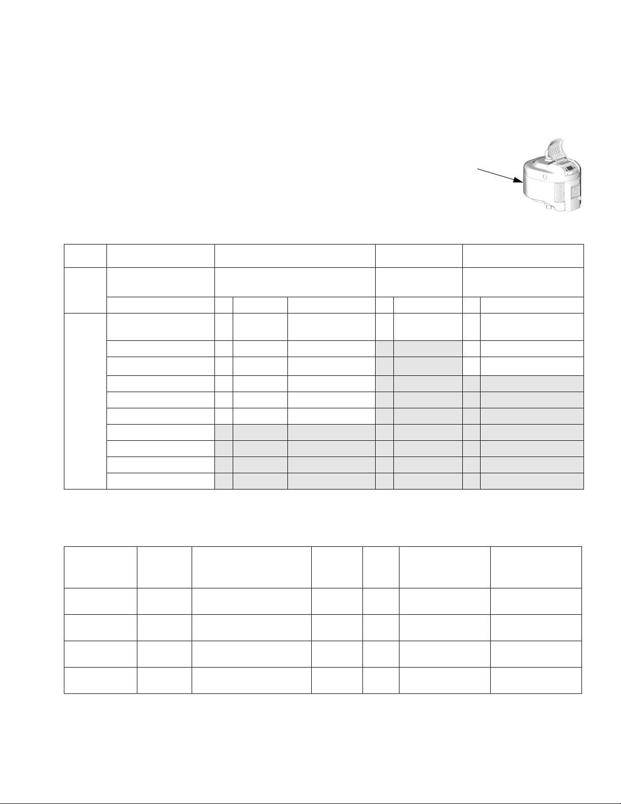
Dura-Flo Pumps with NXT™ Air Motors Part No. Matrix
Check your pump’s identification plate (ID) for the 6-digit part number of your
pump. Use the following matrix to define the construction of your pump, based
on the six digits. For example, Pump Part No. P16MSE represents the
pump (P), pressure ratio (16:1), low noise exhaust motor with DataTrak
™
(M),
stainless steel construction (S), and 4 leather/1 ptfe packing configuration (E).
To order replacement parts, see Parts section starting on page 20. The digits
in the matrix do not correspond to the Ref. Nos. in the Parts drawings and lists.
P16 M S E
ID
Models
First
Digit
P
(pumps)
Second and Third
Digit Fourth Digit Fifth Digit Sixth Digit
Pressure Ratio (xx:1) Exhaust Communication Material Packings
16
21
24
25
30
31
C Low Noise Remote DataTrak S Stainless
Steel
D De-icing none H ptfe/leather
E De-icing DataTrak S
L Low Noise none
M Low Noise DataTrak
H Low Noise High Level Sensor
40
45
46
57
Dura-Flo Pumps with NXT™ Air Motors Part Nos.
Pump Part
No., Series
P16DSE, A 247192 Dura-Flo 1200 (290 cc),
P16ESE, A 247192 Dura-Flo 1200 (290 cc),
P16LSE, A 247192 Dura-Flo 1200 (290 cc),
P16MSE, A 247192 Dura-Flo 1200 (290 cc),
Lower
Part No. Lower Model, Packings
4 leather/1 PTFE
4 leather/1 PTFE
4 leather/1 PTFE
4 leather/1 PTFE
Air
Motor
Part No. Ratio
N22DN0 16:1 10.5, 105 (1520) 0.7, 7.0 (100)
N22DT0 16:1 10.5, 105 (1520) 0.7, 7.0 (100)
N22LN0 16:1 10.5, 105 (1520) 0.7, 7.0 (100)
N22LT0 16:1 10.5, 105 (1520) 0.7, 7.0 (100)
Maximum
Working Pressure
MPa, bar (psi)
E 4 leather/1 ptfe
Severe Duty
Input Pressure
®
Maximum Air
MPa, bar (psi)
311828H 3

Models
Dura-Flo Pumps with NXT™ Air Motors Part Nos. (continued)
Pump Part
No., Series
P21DSE, A 247190 Dura-Flo 900 (220 cc),
P21ESE, A 247190 Dura-Flo 900 (220 cc),
P21LSE, A 247190 Dura-Flo 900 (220 cc),
P21LSS, A L22BSS Dura-Flo 900 (220 cc),
P21MSE, A 247190 Dura-Flo 900 (220 cc),
P21CSS, A L22BSS Dura-Flo 900 (220 cc),
P24DSE, A 261657 Dura-Flo 750 (180 cc),
P24ESE, A 261657 Dura-Flo 750 (180 cc),
P24LSE, A 261657 Dura-Flo 750 (180 cc),
P24MSE, A 261657 Dura-Flo 750 (180 cc),
P25DSE, A 237514 Dura-Flo 1200 (290 cc),
P25ESE, A 237514 Dura-Flo 1200 (290 cc),
P25LSE, A 237514 Dura-Flo 1200 (290 cc),
P25MSE, A 237514 Dura-Flo 1200 (290 cc),
P30DSE, A 236470 Dura-Flo 900 (220 cc),
P30CSS, A L220SS Dura-Flo 900 (220 cc),
P30ESE, A 236470 Dura-Flo 900 (220 cc),
P30LSS, A L220SS Dura-Flo 900 (220 cc),
P30LSE, A 236470 Dura-Flo 900 (220 cc),
P30MSE, A 236470 Dura-Flo 900 (220 cc),
P31DSH, A 247168 Dura-Flo 600 (145 cc),
P31CSS, A L14BSS Dura-Flo 600 (145 cc),
P31ESH, A 247168 Dura-Flo 600 (145 cc),
Lower
Part No. Lower Model, Packings
4 leather/1 PTFE
4 leather/1 PTFE
4 leather/1 PTFE
2 PTFE/3 UHMWP
4 leather/1 PTFE
2 PTFE/3 UHMWP
4 leather/1 PTFE
4 leather/1 PTFE
4 leather/1 PTFE
4 leather/1 PTFE
4 leather/1 PTFE
4 leather/1 PTFE
4 leather/1 PTFE
4 leather/1 PTFE
4 leather/1 PTFE
2 PTFE/3 UHMWP
4 leather/1 PTFE
2 PTFE/3 UHMWP
4 leather/1 PTFE
4 leather/1 PTFE
PTFE/leather
2 PTFE/3 UHMWP
PTFE/leather
Air
Motor
Part No. Ratio
N22DN0 21:1 14.0, 140 (2030) 0.7, 7.0 (100)
N22DT0 21:1 14.0, 140 (2030) 0.7, 7.0 (100)
N22LN0 21:1 14.0, 140 (2030) 0.7, 7.0 (100)
N22LN0 21:1 14.0, 140 (2030) 0.7, 7.0 (100)
N22LT0 21:1 14.0, 140 (2030) 0.7, 7.0 (100)
N22LR0 21:1 14.0, 140 (2030) 0.7, 7.0 (100)
N22DNO 24:1 16.8, 168 (2430) 0.7, 7.0 (100)
N22DTO 24:1 16.8, 168 (2430) 0.7, 7.0 (100)
N22LNO 24:1 16.8, 168 (2430) 0.7, 7.0 (100)
N22LTO 24:1 16.8, 168 (2430) 0.7, 7.0 (100)
N34DN0 25:1 16.4, 164 (2380) 0.7, 7.0 (100)
N34DT0 25:1 16.4, 164 (2380) 0.7, 7.0 (100)
N34LN0 25:1 16.4, 164 (2380) 0.7, 7.0 (100)
N34LT0 25:1 16.4, 164 (2380) 0.7, 7.0 (100)
N34DN0 30:1 21.9, 219 (3170) 0.7, 7.0 (100)
N34LR0 30:1 21.9, 219 (3170) 0.7, 7.0 (100)
N34DT0 30:1 21.9, 219 (3170) 0.7, 7.0 (100)
N34LN0 30:1 21.9, 219 (3170) 0.7, 7.0 (100)
N34LN0 30:1 21.9, 219 (3170) 0.7, 7.0 (100)
N34LT0 30:1 21.9, 219 (3170) 0.7, 7.0 (100)
N22DN0 31:1 21.0, 210 (3040) 0.7, 7.0 (100)
N22LR0 31:1 21.0, 210 (3040) 0.7, 7.0 (100)
N22DT0 31:1 21.0, 210 (3040) 0.7, 7.0 (100)
Maximum
Working Pressure
MPa, bar (psi)
Maximum Air
Input Pressure
MPa, bar (psi)
4 311828H

Dura-Flo Pumps with NXT™ Air Motors Part Nos. (continued)
Models
Pump Part
No., Series
P31LSS, A L14BSS Dura-Flo 600 (145 cc),
P31LSH, A 247168 Dura-Flo 600 (145 cc),
P31MSH, A 247168 Dura-Flo 600 (145 cc),
P40DSE, A 236456 Dura-Flo 750 (180 cc),
P40ESE, A 236456 Dura-Flo 750 (180 cc),
P40LSE, A 236456 Dura-Flo 750 (180 cc),
P40MSE, A 236456 Dura-Flo 750 (180 cc),
P45DSE, A 237514 Dura-Flo 1200 (290 cc),
P45ESE, A 237514 Dura-Flo 1200 (290 cc),
P45LSE, A 237514 Dura-Flo 1200 (290 cc),
P45MSE, A 237514 Dura-Flo 1200 (290 cc),
P45LSS, A L290SS Dura-Flo 1200 (290 cc),
P45CSS, A L290SS Dura-Flo 1200 (290 cc),
P46DSH, A 236458 Dura-Flo 600 (145 cc),
P46HSS, A L145SS Dura-Flo 600 (145 cc),
P46ESH, A 236458 Dura-Flo 600 (145 cc),
P46LSS L145SS Dura-Flo 600 (145 cc),
P46LSH, A 236458 Dura-Flo 600 (145 cc),
P46MSH, A 236458 Dura-Flo 600 (145 cc),
P57LSS L220SS Dura-Flo 900 (220 cc),
Lower
Part No. Lower Model, Packings
2 PTFE/3 UHMWP
PTFE/leather
PTFE/leather
4 leather/1 PTFE
4 leather/1 PTFE
4 leather/1 PTFE
4 leather/1 PTFE
4 leather/1 PTFE
4 leather/1 PTFE
4 leather/1 PTFE
4 leather/1 PTFE
2 PTFE/3 UHMWP
2 PTFE/3 UHMWP
PTFE/leather
2 PTFE/3 UHMWP
PTFE/leather
2 PTFE/3 UHMWP
PTFE/leather
PTFE/leather
2 PTFE/3 UHMWP
Air
Motor
Part No. Ratio
N22LN0 31:1 21.0, 210 (3040) 0.7, 7.0 (100)
N22LN0 31:1 21.0, 210 (3040) 0.7, 7.0 (100)
N22LT0 31:1 21.0, 210 (3040) 0.7, 7.0 (100)
N34DN0 40:1 26.2, 262 (3800) 0.7, 7.0 (100)
N34DT0 40:1 26.2, 262 (3800) 0.7, 7.0 (100)
N34LN0 40:1 26.2, 262 (3800) 0.7, 7.0 (100)
N34LT0 40:1 26.2, 262 (3800) 0.7, 7.0 (100)
N65DN0 45:1 31.4, 314 (4550) 0.7, 7.0 (100)
N65DT0 45:1 31.4, 314 (4550) 0.7, 7.0 (100)
N65LN0 45:1 31.4, 314 (4550) 0.7, 7.0 (100)
N65LT0 45:1 31.4, 314 (4550) 0.7, 7.0 (100)
N65LN0 45:1 31.4, 314 (4550) 0.7, 7.0 (100)
N65LR0 45:1 31.4, 314 (4550) 0.7, 7.0 (100)
N34DN0 46:1 32.8, 328 (4750) 0.7, 7.0 (100)
N34LH0 46:1 32.8, 328 (4750) 0.7, 7.0 (100)
N34DT0 46:1 32.8, 328 (4750) 0.7, 7.0 (100)
N34LN0 46:1 32.8, 328 (4750) 0.7, 7.0 (100)
N34LN0 46:1 32.8, 328 (4750) 0.7, 7.0 (100)
N34LT0 46:1 32.8, 328 (4750) 0.7, 7.0 (100)
N65LN0 57:1 38.7, 388 (5700) 0.7, 7.0 (100)
Maximum
Working Pressure
MPa, bar (psi)
Maximum Air
Input Pressure
MPa, bar (psi)
311828H 5
Models
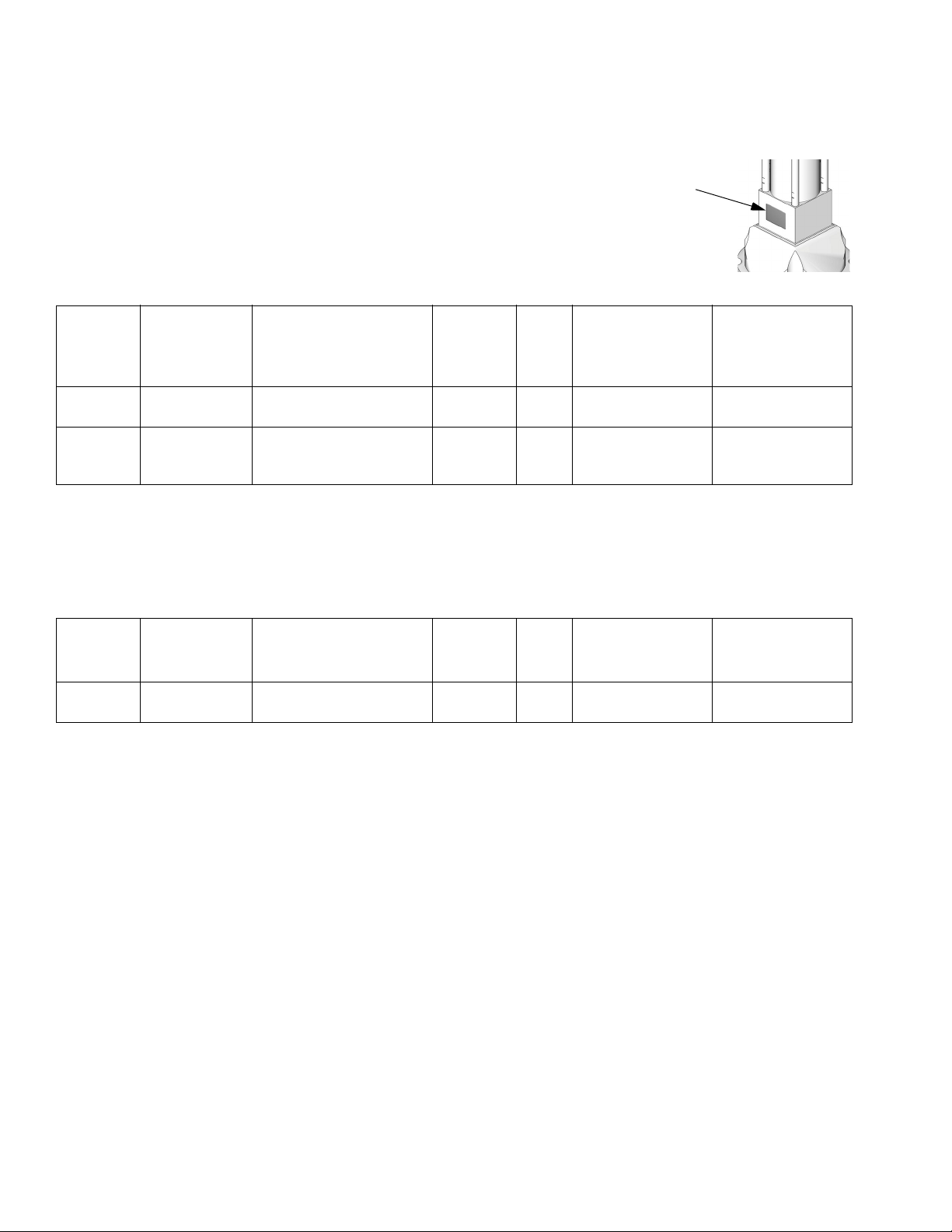
Dura-Flo Pumps with Viscount® Hydraulic Motors
Check your pump’s identification plate (ID) for the 6-digit part number of your
pump. To order replacement parts, see Parts section starting on page 20.
Pump
Part No.,
Series
237290, A 236470 Dura-Flo 900 (220 cc),
248817, A 248816 Dura-Flo 900 (220 cc),
Lower Part
No. Lower Model, Packings
4 leather/1 PTFE
UHMWPE (throat)/
PTFE (piston)
Hydraulic
Motor
Part No. Ratio
235345 3.5:1 34, 345 (5000) 9.9, 99 (1428)
235345 3.5:1 34, 345 (5000) 9.9, 99 (1428)
Maximum
Working Pressure
MPa, bar (psi)
ID
Maximum
Hydraulic Input
Pressure
MPa, bar (psi)
Dura-Flo Pumps with Premier® Motors
To order replacement parts, see Parts section starting on page 20.
Pump
Part No.,
Series
P67LSS L290SS Dura-Flo 1200 (290 cc),
Lower Part
No. Lower Model, Packings
2 PTFE/3 UHMWP
Premier
Motor
Part No. Ratio
222800 67:1 34, 345 (5000) 0.5, 5.0 (75)
Maximum
Working Pressure
MPa, bar (psi)
Maximum Air
Input Pressure
MPa, bar (psi)
6 311828H
Warnings
Warnings
The following warnings are for the setup, use, grounding, maintenance, and repair of this equipment. The exclamation point symbol alerts you to a general warning and the hazard symbol refers to procedure-specific risk. Refer back
to these warnings. Additional, product-specific warnings may be found throughout the body of this manual where
applicable.
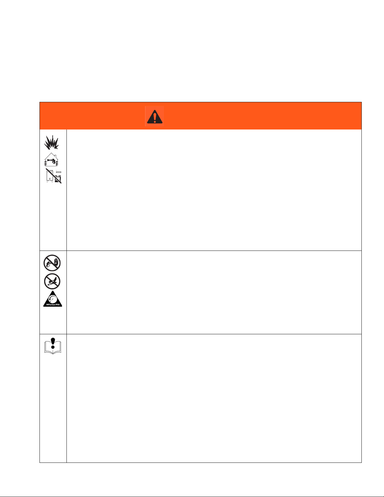
WARNING
FIRE AND EXPLOSION HAZARD
Flammable fumes, such as solvent and paint fumes, in work area can ignite or explode. To help prevent
fire and explosion:
• Use equipment only in well ventilated area.
• Eliminate all ignition sources; such as pilot lights, cigarettes, portable electric lamps, and plastic drop
cloths (potential static arc).
• Keep work area free of debris, including solvent, rags and gasoline.
• Do not plug or unplug power cords, or turn power or light switches on or off when flammable fumes
are present.
• Ground all equipment in the work area. See Grounding instructions.
• Use only grounded hoses.
• Hold gun firmly to side of grounded pail when triggering into pail.
• If there is static sparking or you feel a shock, stop operation immediately. Do not use equipment
until you identify and correct the problem.
• Keep a working fire extinguisher in the work area.
SKIN INJECTION HAZARD
High-pressure fluid from gun, hose leaks, or ruptured components will pierce skin. This may look like just
a cut, but it is a serious injury that can result in amputation. Get immediate surgical treatment.
• Do not point gun at anyone or at any part of the body.
• Do not put your hand over the spray tip.
• Do not stop or deflect leaks with your hand, body, glove, or rag.
• Do not spray without tip guard and trigger guard installed.
• Engage trigger lock when not spraying.
•Follow Pressure Relief Procedure in this manual, when you stop spraying and before cleaning,
checking, or servicing equipment.
EQUIPMENT MISUSE HAZARD
Misuse can cause death or serious injury.
• Do not operate the unit when fatigued or under the influence of drugs or alcohol.
• Do not exceed the maximum working pressure or temperature rating of the lowest rated system
component. See Technical Data in all equipment manuals.
• Use fluids and solvents that are compatible with equipment wetted parts. See Technical Data in all
equipment manuals. Read fluid and solvent manufacturer’s warnings. For complete information
about your material, request MSDS forms from distributor or retailer.
• Check equipment daily. Repair or replace worn or damaged parts immediately with genuine manufacturer’s replacement parts only.
• Do not alter or modify equipment.
• Use equipment only for its intended purpose. Call your distributor for information.
• Route hoses and cables away from traffic areas, sharp edges, moving parts, and hot surfaces.
• Do not kink or over bend hoses or use hoses to pull equipment.
• Keep children and animals away from work area.
• Comply with all applicable safety regulations.
311828H 7
Warnings
WARNING
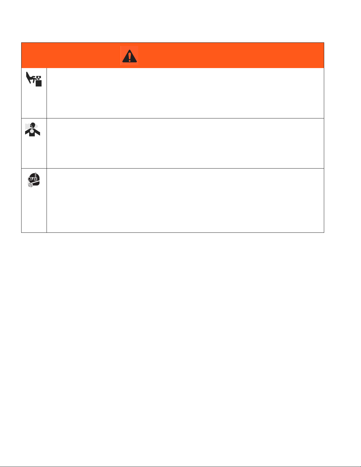
MOVING PARTS HAZARD
Moving parts can pinch or amputate fingers and other body parts.
• Keep clear of moving parts.
• Do not operate equipment with protective guards or covers removed.
• Pressurized equipment can start without warning. Before checking, moving, or servicing equipment,
follow the Pressure Relief Procedure in this manual. Disconnect power or air supply.
TOXIC FLUID OR FUMES HAZARD
Toxic fluids or fumes can cause serious injury or death if splashed in the eyes or on skin, inhaled, or
swallowed.
• Read MSDS’s to know the specific hazards of the fluids you are using.
• Store hazardous fluid in approved containers, and dispose of it according to applicable guidelines.
• Always wear impervious gloves when spraying or cleaning equipment.
PERSONAL PROTECTIVE EQUIPMENT
You must wear appropriate protective equipment when operating, servicing, or when in the operating
area of the equipment to help protect you from serious injury, including eye injury, inhalation of toxic
fumes, burns, and hearing loss. This equipment includes but is not limited to:
• Protective eyewear
• Clothing and respirator as recommended by the fluid and solvent manufacturer
•Gloves
• Hearing protection
8 311828H
Installation
Installation
Grounding
The equipment must be grounded. Grounding reduces
the risk of static and electric shock by providing an
escape wire for the electrical current due to static build
up or in the event of a short circuit.
Pump: Use the ground screw (GS) and lockwasher on
the motor to attach a 244524 ground wire (Y). Tighten
the screw securely. Connect the other end of the ground
wire to a true earth ground.
Y
GS
Air and fluid hoses: use only electrically conductive
hoses.
TI8250a
Flush Before Using Equipment
The equipment was tested with lightweight oil, which is
left in the fluid passages to protect parts. To avoid contaminating your fluid with oil, flush the equipment with a
compatible solvent before using the equipment. See
Flushing, page 15.
Mounting Accessories
See Dimensions, page 24 and Mounting Hole Layouts, page 25.
F
IG
. 1 shows an air-powered system and FIG. 2 shows a
hydraulic-powered system.
Hoses
See FIG. 1 and FIG. 2. Be sure all hoses are properly
sized and pressure-rated for your system. Use only
electrically conductive hoses. Fluid hoses must have
spring guards on both ends. Use a whip hose (P) and a
swivel (R) between the main fluid hose (N) and the
gun/valve (S) to allow freer gun/valve movement.
Air compressor or hydraulic power supply: follow
manufacturer’s recommendations.
Spray gun: ground through connection to a properly
grounded fluid hose and pump.
Fluid supply container: follow local code.
Object being sprayed: follow local code.
Solvent pails used when flushing: follow local code.
Use only conductive metal pails, placed on a grounded
surface. Do not place the pail on a nonconductive surface, such as paper or cardboard, which interrupts
grounding continuity.
To maintain grounding continuity when flushing or
relieving pressure: hold metal part of the spray gun
firmly to the side of a grounded metal pail, then trigger
the gun.
311828H 9
Installation
Air Line Accessories
For air-powered pumps, install the following accessories
in the order shown in F
sary.
NOTE: Accessory Air Control Kits are available for the
NXT Air Motor. The kits include a master air valve (E),
air regulator (F), and filter (J). Order the kit separately.
See manual 311239 for information.
• Bleed-type master air valve (E): required in your
system to relieve air trapped between it and the air
motor when the valve is closed. Be sure the valve is
easily accessible from the pump and located downstream from the air regulator.
• Pump air regulator (F): to control pump speed and
outlet pressure. Locate it close to the pump.
IG
. 1, using adapters as neces-
• Pressure reducing valve (H) with a drain line (E)
runs directly to the hydraulic return line (D).
• Accumulator (J) reduces the hammering effect
caused by the motor reversing direction.
• Return line shutoff valve (V) isolates the pump for
service.
• Be sure your hydraulic power supply is equipped
with a suction filter to the hydraulic pump and a sys-
tem return line filter (W) of 10 micron size.
• Connect a 6 mm (1/4 in.) ID drain line (K) to the
barbed fitting on the drip pan, and place the free end
in a container to collect the drainage.
Fluid Line Accessories
Install the following accessories in the order shown in
F
IG
. 1 and FIG. 2, using adapters as necessary.
• Air line filter (J): removes harmful dirt and moisture
from compressed air supply.
• Second bleed-type air valve (K): isolates air line
accessories for servicing. Locate upstream from all
other air line accessories.
Hydraulic Line Accessories
For hydraulic-powered pumps, install the following
accessories in the order shown in F
as necessary.
• Use a minimum 13 mm (1/2 in.) ID supply line (C),
and a minimum 22 mm (7/8 in.) ID return line (D).
The motor has a 3/4 npt(f) hydraulic oil supply fitting, and a 1 in. npt(f) hydraulic oil return fitting.
• Supply line shutoff valve (U) isolates the pump for
service.
• Fluid pressure gauge (F) monitors hydraulic oil
pressure to the motor to avoid overpressurizing the
motor or displacement pump.
IG
. 2, using adapters
• Fluid drain valve (M): required in your system, to
relieve fluid pressure in the hose and gun.
• Fluid filter (L): with a 60 mesh (250 micron) stainless steel element to filter particles from the fluid as
it leaves the pump.
• Gun or valve (S): to dispense fluid.
• Fluid line swivel (R): for easier gun movement.
• Suction kit (T): enables the pump to draw fluid from
a container.
• Pressure- and temperature-compensated flow
control valve (G) prevents the motor from running
too fast and possibly damaging itself.
10 311828H
Installation
K
J
U
D
E
H
V
F
B
T
A
Y
S
L
P
R
N
M
TI8429a
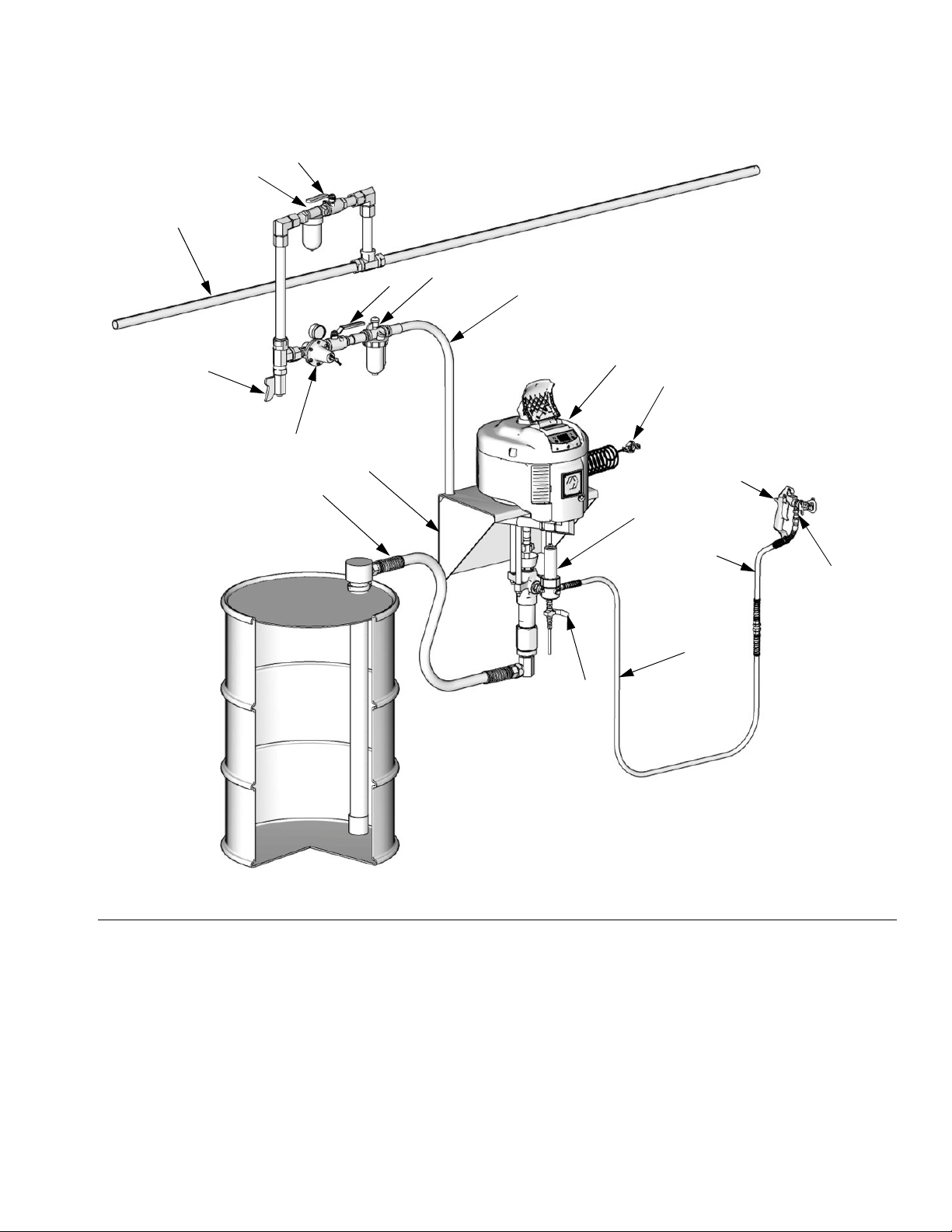
FIG. 1: Typical Installation, Air-Powered Pumps
Key:
APump
B Wall Bracket
D Air Line Lubricator
E Bleed-type Master Air Valve (required)
F Pump Air Regulator
H Electrically Conductive Air Supply Hose
J Air Line Filter
K Air Shutoff Valve
L Fluid Filter
M Fluid Drain Valve (required)
N Electrically Conductive Fluid Supply Hose
311828H 11
P Fluid Whip Hose
R Gun Swivel
S Airless Spray Gun
T Fluid Suction Kit
U Main Air Supply Line
V Air Line Drain Valve
Y Pump Ground Wire (required, see page 9 for installation
instructions)
Loading...