


Instructions – Parts List
BULLDOG HYDRA–CATR FIXED RATIO
Proportioning Pumps
308225K
EN
3000 psi (21 MPa, 207 bar) Maximum Working Pressure
Two or Three Displacement Pump Models in Various Mix Ratios, Pressure Ratios and Flow Volume
Available as Bare Pumps,
Wall-Mounted* or Free-Standing* Models
*Includes Mixing Manifolds, Automatic Pressure Relief Valves,
Check Valves, Pressure Gauges and Regulators
Read warnings and instructions.
For a list of models, see page 6.
Table of Contents
Warnings . . . . . . . . . . . . . . . . . . . . . . . . . . . . . . . . . . . . . . . . . . . . |
. . 2 |
|
|
Model Charts . . . . . . . . . . . . . . . . . . . . . . . . . . . . . . . . . . . . . . . . . |
. . 6 |
|
|
Typical Installations . . . . . . . . . . . . . . . . . . . . . . . . . . . . . . . . . . . |
7, 8 |
|
|
Installation . . . . . . . . . . . . . . . . . . . . . . . . . . . . . . . . . . . . . . . . . . . . |
. 9 |
|
|
Installation – Optional Fluid Heaters . . . . . . . . . . . . . . . . . . . . . . . |
13 |
|
|
Installation – Optional Solvent Pump . . . . . . . . . . . . . . . . . . . . . . |
15 |
|
|
Flushing . . . . . . . . . . . . . . . . . . . . . . . . . . . . . . . . . . . . . . . . . . . . . . |
16 |
|
|
Operation . . . . . . . . . . . . . . . . . . . . . . . . . . . . . . . . . . . . . . . . . . . . . |
19 |
|
|
Shutdown and Care of the System . . . . . . . . . . . . . . . . . . . . . . . . |
23 |
|
|
Troubleshooting . . . . . . . . . . . . . . . . . . . . . . . . . . . . . . . . . . . . . . . |
24 |
|
|
Service – Displacement Pump . . . . . . . . . . . . . . . . . . . . . . . . . . . |
26 |
|
|
Parts . . . . . . . . . . . . . . . . . . . . . . . . . . . . . . . . . . . . . . . . . . . . . . . . |
28 |
|
|
Accessories . . . . . . . . . . . . . . . . . . . . . . . . . . . . . . . . . . . . . . . . . . . |
40 |
|
|
Dimensions . . . . . . . . . . . . . . . . . . . . . . . . . . . . . . . . . . . . . . . . . . . |
43 |
02910A |
|
Technical Data |
45 |
||
|
|||
Graco Standard Warranty . . . . . . . . . . . . . . . . . . . . . . . . . . . . . . . |
46 |
|

Symbols
Warning Symbol
 WARNING
This symbol alerts you to the possibility of serious injury or death if you do not follow the instructions.
Caution Symbol
 CAUTION
This symbol alerts you to the possibility of damage to or destruction of equipment if you do not follow the instructions.
 WARNING
INJECTION HAZARD
Spray from the gun, hose leaks, or ruptured components can inject fluid into your body and cause extremely serious injury, including the need for amputation. Splashing fluid in the eyes or on the skin can also cause serious injury.
DFluid injected into the skin might look like just a cut, but it is a serious injury. Get immediate medical attention.
DDo not point the spray gun at anyone or at any part of the body.
DDo not put your hand or fingers over the spray tip/nozzle.
DDo not stop or deflect leaks with your hand, body, glove or rag.
DDo not “blow back” fluid; this is not an air spray system.
DCheck the gun diffuser operation weekly. Refer to the gun manual.
DAlways have the trigger guard on the spray gun when spraying.
DCheck the gun diffuser operation weekly. Refer to the gun manual.
DBe sure the gun trigger safety operates before spraying.
DLock the gun trigger safety when you stop spraying.
DFollow the Pressure Relief Procedure on page 19 if the spray tip/nozzle clogs and whenever you: are instructed to relieve pressure; stop spraying; clean, check, or service the equipment; and install or clean the spray tip/nozzle.
DTighten all fluid connections before operating the equipment.
DCheck the hoses, tubes, and couplings daily. Do not mend or repair any part of the hose assembly. If the hose is damaged, replace it immediately.
MOVING PARTS HAZARD
Moving parts, such as the air motor piston can pinch or amputate fingers.
DDo not operate the equipment with the air motor plates removed.
DKeep your body and tools clear of any moving parts when starting or operating the equipment.
2308225
 WARNING
FIRE, EXPLOSION, AND ELECTRIC SHOCK HAZARD
Improper grounding, poor ventilation, open flames, or sparks can cause a hazardous condition and result in fire, explosion, electric shock or other serious injury.
DGround the equipment and the object being sprayed. See Grounding on page 10.
DDo not use the heater with flammable liquids, such as those having flash points below 200_ F (93_ C).
DAll electrical wiring must be done by trained and qualified personnel and comply with all local codes and regulations.
DIf there is any static sparking while using the equipment, stop spraying immediately. Identify and correct the problem.
DProvide fresh air ventilation to avoid the buildup of flammable fumes from solvents or the fluid being sprayed.
DDo not smoke within the spray area.
DExtinguish all the open flames or pilot lights within the spray area.
DKeep the spray area free of debris, including solvent, rags, and gasoline.
DElectrically disconnect all the equipment within the spray area.
DDo not turn on or off any light switch within the spray area while operating or if fumes are present.
DDo not operate a gasoline engine within the spray area.
TOXIC FLUID HAZARD
Hazardous fluid or toxic fumes can cause serious injury or death if splashed in the eyes or on the skin, inhaled, or swallowed.
DKnow the specific hazards of the fluid you are using.
DStore hazardous fluid in an approved container. Dispose of hazardous fluid according to all local, state and national guidelines.
DAlways wear protective eyewear, gloves, clothing and respirator as recommended by the fluid and solvent manufacturer.
DGraco does not manufacture or supply any of the reactive chemical components that may be used in this equipment and is not responsible for their effects. Graco assumes no responsibility for loss, damage, expense or claims for personal injury or property damage, direct or consequential, arising from the use of such chemical components.
308225 3

 WARNING
EQUIPMENT MISUSE HAZARD
Equipment misuse can cause the equipment to rupture or malfunction and result in serious injury.
INSTRUCTIONS
DThis equipment is for professional use only.
DRead all instruction manuals, tags, and labels before operating the equipment.
DUse the equipment only for its intended purpose. If you are uncertain about usage, call your Graco distributor.
DDo not alter or modify this equipment. Use only genuine Graco parts and accessories.
DCheck equipment daily. Repair or replace worn or damaged parts immediately.
DSee the chart on page 6 for important pressure rating information. The maximum working pressure of each model is also shown on the pump identification plate. Be sure that all dispensing equipment and accessories are rated to withstand the maximum working pressure of your pump. Do not exceed the maximum working pressure of the lowest rated system component.
DNever operate the pump without the automatic pressure relief valves and drainage kits installed. These valves relieve fluid pressure through a drain port at the bottom of the valve if the displacement pump pressure exceeds the working pressure.
DDo not lift pressurized equipment.
DUse only Graco approved hoses. Do not remove hose spring guards, which help protect the hose from rupture caused by kinks or bends near the couplings.
DRoute the hoses away from the traffic areas, sharp edges, moving parts, and hot surfaces. Do not expose Graco hoses to temperatures above 180_F (82_C) or below –40_F (–40_C).
DDo not use the hoses to pull the equipment.
DUse fluids and solvents that are compatible with the equipment wetted parts. See the Technical Data section of all the equipment manuals. Read the fluid and solvent manufacturer’s warnings.
DComply with all applicable local, state and national fire, electrical and other safety regulations.
4308225

Notes
head.notes
308225 5

Model Charts
Pressure and Ratio Ratings for Bulldog Pumps
 WARNING
COMPONENT RUPTURE HAZARD
To reduce the risk of over-pressurizing a component, which can result in an explosion and serious injury, never operate the system at a working pressure higher than the lowest rated component in the system. All fluid side components, such as dispensing valves; regulators; and hoses, must have a working pressure equal to or greater than the pressure given in Column B for each pump model.
Column A gives the maximum pump fluid output pressure.
Column B gives the minimum working pressure required for all system components, based on the automatic relief valve settings. Components included by Graco with the models listed meet or exceed this requirement.
Models with Two Displacement Pumps
|
|
|
|
|
A |
|
|
|
B |
|
|
|
|
|
|
|
|
Maximum Pump |
At Maximum |
Minimum |
Normal |
Nominal |
|||||
|
|
|
|
Flow |
|||||||||
|
|
Model No. |
|
Fluid Output |
Air Pressure |
Component |
|||||||
|
|
|
Pressure |
Volume |
|||||||||
|
|
|
|
Pressure* |
|
Of: |
Working Pressure |
||||||
|
|
|
|
|
Ratio |
@ 40 cpm |
|||||||
Mix |
|
|
|
|
|
|
|
|
|
||||
|
|
|
|
|
|
|
|
|
(Fluid to Air) |
|
|
||
Bare |
Wall |
Stand |
psi |
MPa, bar |
psi |
MPa, bar |
psi |
MPA, bar |
gpm |
lpm |
|||
Ratio |
|
||||||||||||
|
|
|
|
|
|
|
|
|
|
|
|
||
1:1 |
231897 |
231836 |
231865 |
3000 |
21, 207 |
86 |
0.6, 6 |
3000 |
21, 207 |
34.7 |
1.8 |
6.8 |
|
Models with Three Displacement Pumps
|
|
|
|
|
A |
|
|
|
B |
|
|
|
|
|
|
|
Maximum Pump |
At Maximum |
Minimum |
Normal |
Nominal |
||||
|
|
|
|
Flow |
||||||||
|
|
Model No. |
|
Fluid Output |
Air Pressure |
Component |
Pressure |
|||||
|
|
|
Volume |
|||||||||
|
|
|
|
Pressure* |
|
Of |
Working Pressure |
Ratio |
||||
Mix |
|
|
|
|
@ 40 cpm |
|||||||
|
|
|
|
|
|
|
|
|
(Fluid to Air) |
|
|
|
Ratio |
Bare |
Wall |
Stand |
psi |
MPA, bar |
psi |
MPa, bar |
psi |
MPA, bar |
|
gpm |
lpm |
2:1 |
231908 |
231847 |
231876 |
2320 |
16, 160 |
100 |
0.7, 7 |
2900 |
20, 200 |
23.2 |
2.7 |
10.1 |
|
|
|
|
|
|
|
|
|
|
|
|
|
2:1 |
231910 |
231849 |
231878 |
3000 |
21, 207 |
86 |
0.6, 6 |
3600 |
25, 248 |
34.7 |
1.8 |
6.7 |
|
|
|
|
|
|
|
|
|
|
|
|
|
3:1 |
231912 |
231851 |
231880 |
2610 |
18, 180 |
100 |
0.7, 7 |
2900 |
20, 200 |
26.1 |
2.4 |
8.9 |
|
|
|
|
|
|
|
|
|
|
|
|
|
4:1 |
231915 |
231854 |
231883 |
2780 |
19, 192 |
100 |
0.7, 7 |
2900 |
20, 200 |
27.8 |
2.2 |
8.4 |
|
|
|
|
|
|
|
|
|
|
|
|
|
6308225

Typical Installation
About the Typical Installations
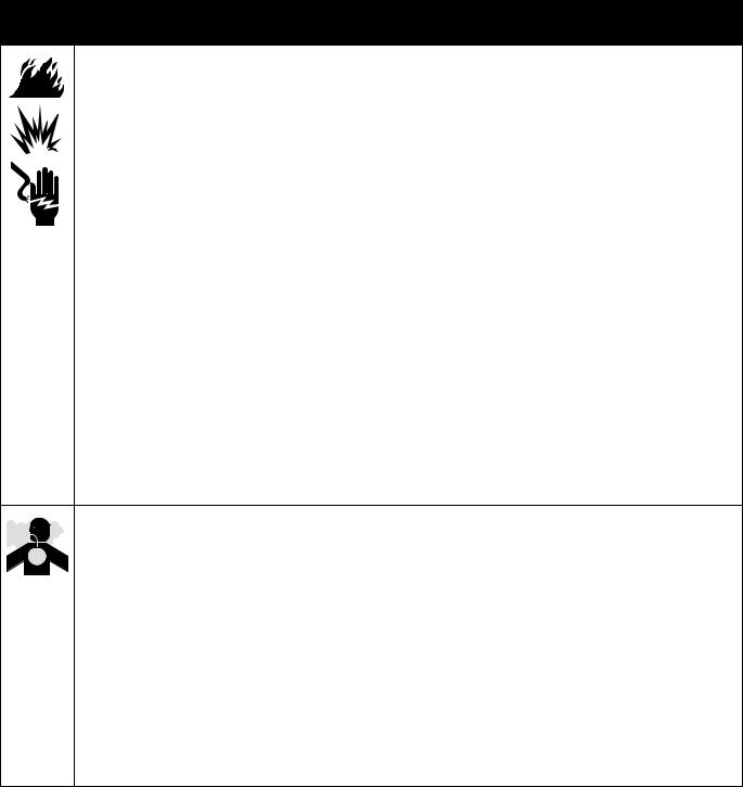
These pumps are designed to be part of a Hydra-Cat dispensing system that will proportion, mix, and dispense two-component fluids. The typical installations shown below and on page 8 are only guidelines to setting up a complete proportioning system. For clarity, various components are shown in the correct order but may not be shown in the exact position of the installed system. For assistance in designing your system, contact your nearest Graco representative.
NOTE: When pressure feeding the proportioning pump, mount fluid pressure gauges (J) at the proportioning pump inlets to monitor proper adjustment of the feed pump pressures. Never exceed 25% of the Hydra-Cat pump outbound fluid pressure on the feed supply.
Light Viscosity System
Two Displacement Pumps,
5:1 Ratio Feed Pumps
KEY
A |
Bleed-type master |
H |
Proportioning pump |
P |
Fluid drain valve |
|
air valve |
J |
Fluid pressure gauge |
Q |
Fluid shutoff valve |
B |
Air filter |
K |
Check valve |
R |
Static mixer |
C |
Air lubricator |
L |
Automatic pressure relief |
S |
Dispense valve |
D |
Pump runaway valve |
|
valve |
T |
Fluid regulator |
E |
Pump air regulator |
M |
Fluid filter |
U |
Solvent pump |
F |
Feed pump |
N |
Mixer manifold |
V |
Fluid strainer |
G |
Ground wire |
|
|
|
|
1See note above
2Connect to drain bottle.
See Fig. 5, page 11
*Included with wall or stand models
B A
F G |
H E* A* |
K* |
C
D
2
|
|
|
HARD |
|
|
|
|
RES |
|
E |
HARDENER |
RESIN |
J* |
1 |
A |
|
|
||
|
|
V* |
|
|
|
|
|
|
|
|
|
|
Q* |
|
Fig. 1
L*
M S
N*
P*
HARD R
RES |
Q |
|
|
||
Q* |
T |
|
U |
||
K |
||
|
||
|
M |
02911
308225 7

Typical Installation
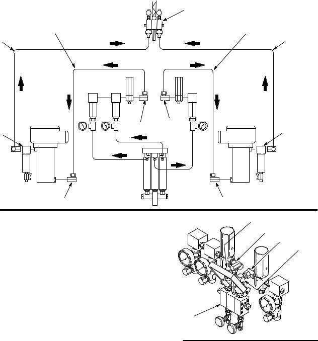
About the Typical Installations
These pumps are designed to be part of a Hydra-Cat dispensing system that will proportion, mix, and dispense two-component fluids. The typical installation iss shown below and on page 7 are only a guidelines to setting up a complete proportioning system. For clarity, various components are shown in the correct order but may not be shown in the exact position of the installed system. For assistance in designing your system, contact your nearest Graco representative.
NOTE: When pressure feeding the proportioning pump, mount fluid pressure gauges (J) at the proportioning pump inlets to monitor proper adjustment of the feed pump pressures. Never exceed 25% of the Hydra-Cat pump outbound fluid pressure on the feed supply.
Heavy Viscosity Heated System
Three Displacement Pumps,
10:1 Ratio Feed Pumps
KEY
A |
Bleed-type master air valve |
J |
Fluid pressure gauge |
R |
Static mixer |
B |
Air filter |
K |
Check valve |
S |
Dispense valve |
C |
Air lubricator |
L |
Automatic pressure |
T |
Fluid regulator |
D |
Pump runaway valve |
|
relief valve |
U |
Solvent pump |
E |
Pump air regulator |
M |
Fluid filter |
V |
Fluid strainer |
F |
Feed pump |
N |
Mixer manifold |
W |
Fluid heater |
G |
Ground wire |
P |
Fluid drain valve |
X |
Supply manifold |
H |
Proportioning pump |
Q |
Fluid shutoff valve |
|
|
1See note above
2Connect to drain bottle. See Fig. 5, page 11
*Included with wall or stand models
B A |
|
|
F G |
H E* A* |
J* K* L* W M |
|
|
S |
C |
|
N** |
|
P** |
|
|
|
|
D |
|
R |
|
|
|
|
2 |
|
|
|
|
Q |
|
|
Q** |
T |
|
|
K |
U |
|
|
|
M |
|
|
2 |
|
E |
X* |
|
|
A |
|
|
|
J* |
1 |
|
|
|
|
||
|
V* |
|
|
|
Q* |
|
|
Fig. 2 |
02912 |
|
8308225
Installation
Bare Pumps
Bare pumps are available for those installations which require a highly customized system. For a safe and efficient system, Graco recommends that the air and fluid components supplied with the Wall Mount and Cart Mount models also be used in customized systems. Refer to the Parts Drawings starting on page 28 for part numbers. In addition, the accessories shown in the Typical Installation drawings and discussed in the following pages of this manual should be used.
Be sure all accessories are sized properly for the air and fluid requirements of your system.
Read all instructions in the Installation section for further details.
NOTES:
1.Models with three displacement pumps always use the two outer displacement pumps to supply the resin and the middle displacement pump to supply the hardener.
2.Label all pumps, hoses, fluid regulators, etc. to indicate whether they are for the resin side or hardener side of the system.
Mounting the Pump
Mount the pump to suit your installation. The bare pump can be mounted on a wall bracket or on a cart. See Dimensions on page 43. The Bulldog pump and accessories weigh approximately 115 lb (52 kg). The pump stand and accessories weigh 55 lb (25 kg).
For a wall mount, be sure the bracket and wall are strong enough to support the pump, accessories, plumbing and stress caused by pump operation.
Locate the bracket about 5 ft (1.5 m) above the floor.
308225 9

Installation
Grounding
WARNING
FIRE AND EXPLOSION HAZARD
Improper grounding could cause static sparking, which could cause a fire or explosion. To reduce the risk of property damage or serious injury, follow the grounding instructions below.
The following grounding instructions are minimum requirements for a system. Your system may include other equipment or objects which must be grounded. Check your local electrical code for detailed grounding instructions for your area and type of equipment. Your system must be connected to a true earth ground.
1.Pump:
a.Loosen the grounding lug locknut (BB) and washer (AA).
b.Insert one end of a 14 ga. (1.5 mm@) minimum ground wire (G) into the slot in lug (CC) and tighten the locknut securely. See Fig. 3.
c.Connect the other end of the ground wire to a true earth ground. Order part number 237569 grounding clamp wire.
G
CC
2.Air hoses: use only grounded hoses with a maximum of 500 feet (150 m) combined hose length to ensure grounding continuity.
3.Fluid hoses: use only grounded fluid hoses.
4.Air compressor: follow manufacturer’s recommendations.
5.Spray gun or dispensing valve: grounding is obtained through connection to a properly grounded fluid hose and pump.
6.Fluid supply container: according to local code.
7.Object being sprayed: according to your local code.
8.All solvent pails used when flushing, according to local code. Use only metal pails, which are conductive, placed on a grounded surface. Do not place the pail on a nonconductive surface, such as paper or cardboard, which interrupts the grounding continuity.
9.To maintain grounding continuity when flushing or relieving pressure, always hold a metal part of the dispensing unit firmly to the side of a grounded metal pail, then trigger the dispensing unit.
BB AA
Fig. 3
10 308225
Installation
Air Control Accessories
Install the accessories in the order shown in Fig. 4. Mount only the air regulator (E) and a master air valve
(A) at the pump. Mount all other accessories on separate wall brackets to reduce stress on the pump inlet. Note that one air filter (B) can serve multiple pumps by using an air manifold downstream from the air filter.
 WARNING
INJECTION HAZARD
Bleed-type master air valves (A) are required in the system in the positions shown in the Typical Installation drawings. These valves are used during system pressure relief to relieve air trapped in the air line. Trapped air can cause the pump to cycle unexpectedly and result in serious injury from moving parts, fluid injection, or fluid splashing.
B A
A
E
G
C
D
Fig. 4 |
02887 |
|
1.Install a bleed-type master air valve (A) in the pump air inlet.
2.Install an air regulator and gauge (E) to control pump outlet pressure.
3.Install a pump runaway valve (D) for each feed pump to automatically shut off the air to the pump if the pump accelerates beyond the pre-adjusted setting. A pump which runs too fast can be seriously damaged.
4.Install an air line lubricator (C) for automatic air motor lubrication.
5.Install an air filter (B) to remove harmful dirt and moisture from the compressed air supply.
Automatic Pressure Relief Valves
 WARNING
COMPONENT RUPTURE HAZARD
To reduce the risk of component rupture, which could cause serious injury and
property damage, the appropriate automatic pressure relief valve (18) is required for each fluid on a plural component pump.
These valves automatically relieve fluid pressure if the pump output pressure exceeds the valve’s preset pressure. Over-pressurization may occur if there is a fluid line clog upstream from the valve or if any other condition exists that causes one of the pumps to cavitate and direct all fluid pressure to the other pump(s).
See the Model Chart on page 6 to determine the preset pressure in your system.
NOTE: Item 38, Drainage Bottle Kit, includes items 38a–38h
 18
18
38a
38b
38c
38f
38g
38h
Fig. 5 |
02888A |
|
|
|
|
308225 11

Installation
Automatic Pressure Relief Valves (continued)
Two drainage bottle kits (38) are included with wall models (unassembled) and stand mount models (assembled) to catch the drainage if the automatic pressure relief valves (18) open.
For the wall mount models, assemble the kit as shown in Fig. 5, page 11, and mount it securely to a wall or bracket. Use the tie wrap, supplied, to hold the hoses out of the way if necessary.
 WARNING
INJECTION HAZARD
Fluid emitted from the automatic pressure drain valves may be at pressures over 3000 psi (21 MPa, 207 bar). To reduce the risk of serious injury from fluid injection or fluid splashing, make sure the drain bottles are securely fastened to the frame or wall so that they can handle a sudden spurt of pressurized fluid.
Connect Fluid Supply Hoses
NOTE: If you mount the pump on a wall, turn the displacement pump inlet assemblies (CC) to face forward, rather than backwards as shown in Fig. 76.
For Two Displacement Pump Models
1.Connect the resin supply hose (EE) to the 3/4 npt swivel inlet (37B) for the resin displacement pump. See Fig. 6.
2.Connect the hardener supply hose (DD) to the
3/4 npt swivel inlet (37A) for the hardener displacement pump. See Fig. 6.
For Three Displacement Pump Models
1.Connect the resin supply hose (EE) to the 3/4 npt swivel inlet (37B) for the resin displacement pumps. See Fig. 7.
2.Connect the hardener supply hose (DD) to the 3/4 npt swivel inlet (37) for the center (hardener) displacement pump. See Fig. 7.
Additional System Components
Install and connect the feed pumps, solvent pump, heaters, etc. Refer to the Typical Installations page 7 and Accessories on pages 40 and 41 for parts information.
Use a dry air kit or a nitrogen regulator kit to protect the fluid in the supply containers from moisture that can crystallize the fluid and cause the ball checks to malfunction. See Accessories on page 41.
DD
EE
37B
HARD
RES
37A
CC
02889
Fig. 6
37B
RES |
HARD |
RES |
EE |
|
|
|
DD
37A
02890
Fig. 7
12 308225

Installation – Optional Fluid Heaters
All Models
NOTE: For systems requiring one heater for each fluid, see page 40 to order the heaters and required plumbing (items 201 to 205).
201a |
|
1. Mount a heater to each side of the mounting |
201b |
|
|
|
bracket using the three screws (201a) and lock- |
|
201 |
|
|
|
washers (201b) supplied with each heater. See |
|
|
202 |
|
|
Fig. 8. |
|
|
|
|
|
|
204 |
|
|
2. Connect a swivel union (202) to the outlet of each |
|
|
heater. See Fig. 8. |
OUT |
|
|
|
|
3. Connect a swivel union (203) to the inlet of each |
IN |
|
heater. See Fig. 8. |
|
|
For Two Displacement Pump Models
2031. Disconnect the existing hardener hose (10B) from the inlet of the mixer manifold (23). See Fig. 8.
10 |
Connect the free end of the hose to the swivel |
|
(203) at the hardener heater inlet. See Fig. 9. |
||
|
Fig. 8 |
02913A |
|
 WARNING
INJECTION HAZARD
To reduce the risk of serious injury, follow the Pressure Relief Procedure on page 19 before installing the heaters.
RES
204A
202A
2.Install a new fluid hose (204B) between the hardener heater outlet (202B) and the hardener mixer manifold. See Fig. 8 and 9.
3.Repeat Steps 1 and 2 for the resin pump (the “A” side).
See Three Displacement Pump Models on next page.
23
HARD |
204B |
|
202B
RES
|
OUT |
|
203A |
RES |
HARD |
|
|
|
|
IN |
HARD |
|
RES |
HARD
OUT
203B
IN
10A 10B
Fig. 9 |
02893 |
308225 13
Installation – Optional Fluid Heaters
205A
FA
202A |
RES |
|
HEATER |
|
OUT |
|
IN |
|
23 |
|
|
|
204B |
RES |
HARD |
FB |
|
||
RES |
HARD |
|
17A 17B
HARD |
202B |
|
|
HEATER |
|
OUT |
|
RES |
RES HARD |
IN |
|
|
203A |
203B |
Fig. 10 |
02894 |
|
|
For Three Displacement Pump Models |
16A |
NOTE: You must provide two hoses (FA, FB in Fig.10) |
17A |
and fittings to run from the heater outlets to the mixer |
17B |
|
16B |
||
manifold inlets. |
||
|
NOTE: To accommodate two resin fluid hoses, the mixer manifold (23) must be disconnected from the bracket and mounted remotely.
1. Loosen the swivel of the unions (17A, 17B) to |
RES |
HARD |
|
remove the elbow (16A, 16B) on each side of the |
|||
|
|
||
mixer manifold (23). Turn the unions (17A, 17B) so |
23 |
|
|
the outlet faces up. See Fig. 10 and 11. |
|
||
|
|
||
2. Connect a new hardener fluid hose (204B) |
Fig. 11 |
02892A |
|
|
|||
between the union (17B) and the swivel (203B) at |
|
||
|
|
||
the heater inlet. See Fig. 10. |
|
|
3.Install another hardener fluid hose (FB) between the heater outlet elbow (202B) and the hardener side of the mixer manifold (23). See Fig. 10.
4.Repeat Steps 1 to 3 for the resin side of the system (the “A” side).
14 308225
 Loading...