


 Loading...
Graco Inc. 246025, 246026, 246030, 246031, 246034 Operation
...Operation
309551H
Electric, Heated, Plural Component
Proportioner
For spraying polyurethane foam and polyurea coatings. Not for use in explosive atmospheres.
See Models and Maximum Working Pressures on page 3.
Important Safety Instructions
Read all warnings and instructions in this manual. Save these instructions.
TI3764a-1
Graco Inc. P.O. Box 1441 Minneapolis, MN 55440-1441
Copyright 2003, Graco Inc. is registered to I.S. EN ISO 9001
Contents
Models . . . . . . . . . . . . . . . . . . . . . . . . . . . . . . . . . . . 3 Related Manuals . . . . . . . . . . . . . . . . . . . . . . . . . . . 4 Manual Conventions . . . . . . . . . . . . . . . . . . . . . . . . 4 Warning . . . . . . . . . . . . . . . . . . . . . . . . . . . . . . . . . . . 5 Typical Installation, with circulation . . . . . . . . . . . 7 Typical Installation, without circulation . . . . . . . . 8 Component Identification . . . . . . . . . . . . . . . . . . . . 9 Temperature Controls and Indicators . . . . . . . . . 10 Motor Controls and Indicators . . . . . . . . . . . . . . . 12 Moisture Sensitivity of Isocyanates . . . . . . . . . . . 15 Spray Adjustments . . . . . . . . . . . . . . . . . . . . . . . . 15 Setup . . . . . . . . . . . . . . . . . . . . . . . . . . . . . . . . . . . . 16 Startup . . . . . . . . . . . . . . . . . . . . . . . . . . . . . . . . . . 26
Spraying . . . . . . . . . . . . . . . . . . . . . . . . . . . . . . . . . 29
Shutdown . . . . . . . . . . . . . . . . . . . . . . . . . . . . . . . . 31
Pressure Relief Procedure . . . . . . . . . . . . . . . . . . 32
Fluid Circulation . . . . . . . . . . . . . . . . . . . . . . . . . . . 33
Jog Mode . . . . . . . . . . . . . . . . . . . . . . . . . . . . . . . . 35
Diagnostic Codes . . . . . . . . . . . . . . . . . . . . . . . . . . 36
Maintenance . . . . . . . . . . . . . . . . . . . . . . . . . . . . . . 37
Flushing . . . . . . . . . . . . . . . . . . . . . . . . . . . . . . . . . 37
Accessories . . . . . . . . . . . . . . . . . . . . . . . . . . . . . . 38
Dimensions . . . . . . . . . . . . . . . . . . . . . . . . . . . . . . . 39
Technical Data . . . . . . . . . . . . . . . . . . . . . . . . . . . . 41
Graco Standard Warranty . . . . . . . . . . . . . . . . . . . 42
Graco Information . . . . . . . . . . . . . . . . . . . . . . . . . 42
2 |
309551H |
26
26
Models
E SERIES
|
|
|
|
|
Flow |
Output per |
Maximum Fluid |
||
|
|
|
Voltage |
Heater |
lb/min |
Cycle (A + B) |
Working Pressure |
||
Part No. |
Series |
Model |
(phase) |
Watts |
(kg/min) |
gal. (liter) |
psi (MPa, bar) |
||
|
|
|
|
|
|
|
|
|
|
246025 |
C |
E-20 |
230V (1) |
6,000 |
20 |
(9) |
.0104 |
(.0395) |
2000 (14, 140) |
246026 |
B |
E-30 |
230V (1) |
10,200 |
30 |
(13.5) |
.0272 |
(0.1034) |
2000 (14, 140) |
246030 |
C |
E-20 |
380V (3) |
6,000 |
20 |
(9) |
.0104 |
(.0395) |
2000 (14, 140) |
246031 |
B |
E-30 |
380V (3) |
10,200 |
30 |
(13.5) |
.0272 |
(0.1034) |
2000 (14, 140) |
246034 |
C |
E-20 |
230V (3) |
6,000 |
20 |
(9) |
.0104 |
(.0395) |
2000 (14, 140) |
246035 |
B |
E-30 |
230V (3) |
10,200 |
30 |
(13.5) |
.0272 |
(0.1034) |
2000 (14, 140) |
248657 |
A |
E-30 with |
230V (1) |
15,300 |
30 |
(13.5) |
.0272 |
(0.1034) |
2000 (14, 140) |
|
|
15.3kW |
|
|
|
|
|
|
|
248658 |
A |
E-30 with |
230V (3) |
15,300 |
30 |
(13.5) |
.0272 |
(0.1034) |
2000 (14, 140) |
|
|
15.3kW |
|
|
|
|
|
|
|
248659 |
A |
E-30 with |
380V (3) |
15,300 |
30 |
(13.5) |
.0272 |
(0.1034) |
2000 (14, 140) |
|
|
15.3kW |
|
|
|
|
|
|
|
E-XP SERIES
|
|
|
|
|
Flow |
Output per |
Maximum Fluid |
|
|
|
Voltage |
Heater |
gpm |
Cycle (A + B) |
Working Pressure |
Part No. |
Series |
Model |
(phase) |
Watts |
(lpm) |
gal. (liter) |
psi (MPa, bar) |
|
|
|
|
|
|
|
|
246024 |
B |
E-XP1 |
230V (1) |
10,200 |
1 (3.8) |
.0104 (.0395) |
2500 (17.2, 172) |
246028 |
B |
E-XP2 |
230V (1) |
15,300 |
2 (7.6) |
.0203 (.0771) |
3500 (24.1, 241) |
246029 |
B |
E-XP1 |
380V (3) |
10,200 |
1 (3.8) |
.0104 (.0395) |
2500 (17.2, 172) |
246032 |
B |
E-XP2 |
380V (3) |
15,300 |
2 (7.6) |
.0203 (.0771) |
3500 (24.1, 241) |
246033 |
B |
E-XP1 |
230V (3) |
10,200 |
1 (3.8) |
.0104 (.0395) |
2500 (17.2, 172) |
246036 |
B |
E-XP2 |
230V (3) |
15,300 |
2 (7.6) |
.0203 (.0771) |
3500 (24.1, 241) |
309551H |
3 |

Related Manuals
The following manuals are shipped with the Reactor™
Proportioner and the Fusion™ Spray Gun. Refer to these manuals for detailed equipment information.
Order Part No. 15B535 for a compact disk of Reactor manuals translated in several languages.
Order Part No. 15B381 for a compact disk of Fusion manual translated in several languages.
Reactor Electric Proportioner
Part No. Description
309574 Reactor Electric Proportioner,
Repair-Parts Manual (English)
309577 Displacement Pump,
Repair-Parts Manual (English)
Reactor Electrical Diagrams (one of the following is included)
Part No. Description
309726 Electrical Diagrams, E-XP1 and
E-20, 230V, 1 phase
309727 Electrical Diagrams, E-XP2 and
E-30, 230V, 1 phase
309728 Electrical Diagrams, E-XP1 and
E-20, 380V, 3 phase
309729 Electrical Diagrams, E-XP2 and
E-30, 380V, 3 phase
309730 Electrical Diagrams, E-XP1 and
E-20, 230V, 3 phase
309731 Electrical Diagrams, E-XP2 and
E-30, 230V, 3 phase
Reactor Data Reporting Kit
Part No. Description
309867 Instruction Manual (English)
Fusion Spray Gun
Part No. Description
309550 Instruction Manual (English)
Heated Hose
Part No. Description
309572 Instruction Manual (English)
Related Manuals
Manual Conventions
Warning
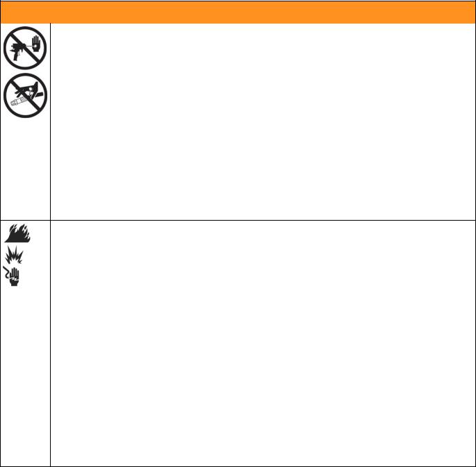
WARNING
A warning alerts you to possible serious injury or death if you do not follow instructions.
Symbols, such as fluid injection (shown), alert you to a specific hazard and direct you to read the indicated hazard warnings on pages 5-6.
Caution
CAUTION
A caution alerts you to possible equipment damage or destruction if you do not follow instructions.
Note
 A note indicates additional helpful information.
4 |
309551H |
Warning
 WARNING
SKIN INJECTION HAZARD
High-pressure fluid from gun, hose leaks, or ruptured components will pierce skin. This may look like just a cut, but it is a serious injury that can result in amputation. Get immediate surgical treatment.
•Do not point the gun at anyone or at any part of the body.
•Do not put your hand or fingers over the gun fluid nozzle.
•Do not stop or deflect leaks with your hand, body, glove, or rag.
•Do not “blow back” fluid; this is not an air spray system.
•Follow Pressure Relief Procedure, page 32, when you stop spraying and before cleaning, checking, or servicing equipment.
•Use lowest possible pressure when flushing, priming, or troubleshooting.
•Engage spray gun piston safety lock when not spraying.
•Tighten all fluid connections before operating the equipment.
•Check hoses, tubes, and couplings daily. Replace worn or damaged parts immediately. High pressure hose cannot be recoupled; replace the entire hose.
FIRE, EXPLOSION AND ELECTRIC SHOCK HAZARD
Solvent and fumes in work area can ignite or explode. High voltage components can cause electric shock. To help prevent fire, explosion, and electric shock:
•Shut off main power switch and wait 5 minutes before opening Reactor cabinet door.
•All electrical wiring must be done by trained and qualified personnel and comply with all local codes.
•Ground equipment and conductive objects. See Ground system, page 24.
•Use equipment only in well ventilated area.
•Eliminate all ignition sources, such as pilot lights, cigarettes and plastic drop cloths (potential static arc).
•Do not plug or unplug power cords or turn lights on or off when flammable fumes are present.
•Keep the work area free of debris, including solvent, rags, and gasoline.
•Hold gun firmly to side of grounded pail when triggering into pail.
•Use only grounded hoses.
•If there is static sparking or you feel a shock, stop operation immediately. Do not use equipment until you identify and correct the problem.
•To avoid chemical reaction and explosion, do not use 1,1,1-trichloroethane, methylene chloride, other halogenated hydrocarbon solvents or fluids containing such solvents in pressurized aluminum equipment.
309551H |
5 |

Warning
 WARNING
EQUIPMENT MISUSE HAZARD
Misuse can cause serious injury or death.
•For professional use only.
•Use equipment only for its intended purpose. Call your Graco distributor for information.
•Read manuals, warnings, tags, and labels before operating equipment. Follow instructions.
•Check equipment daily. Repair or replace worn or damaged parts immediately.
•Do not alter or modify equipment. Use only Graco parts and accessories.
•Do not exceed the maximum working pressure or temperature rating of the lowest rated system component. See Technical Data in all equipment manuals.
•Use fluids and solvents that are compatible with equipment wetted parts. See Technical Data in all equipment manuals. Read fluid and solvent manufacturer’s warnings.
•Route hoses and cables away from traffic areas, sharp edges, moving parts, and hot surfaces.
•Do not use hoses to pull equipment.
•Comply with all applicable safety regulations.
BURN HAZARD
This equipment is used with heated fluid, which can cause equipment surfaces to become very hot. To avoid severe burns:
•Do not touch hot fluid or equipment.
•Allow equipment to cool completely before touching it.
•Wear gloves if fluid temperature exceeds 110°F (43°C).
TOXIC FLUID OR FUMES HAZARD
Toxic fluids or fumes can cause serious injury or death if splashed in the eyes or on skin, inhaled, or swallowed.
•Read Material Safety Data Sheet (MSDS) to know the specific hazards of the fluids you are using.
•Store hazardous fluid in approved containers, and dispose of it according to applicable guidelines.
PERSONAL PROTECTIVE EQUIPMENT
You must wear proper protective equipment when operating, servicing, or when in the operating area of the equipment to help protect you from serious injury, including eye injury; inhalation of toxic fumes; and hearing loss. This equipment includes but is not limited to:
•Protective eyewear.
•Gloves, clothing, and respirator as recommended by the fluid and solvent manufacturer.
•Hearing protection.
6 |
309551H |

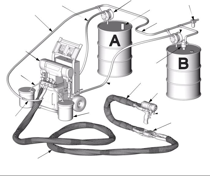
Typical Installation, with circulation
Typical Installation, with circulation
Key for FIG. 1
A |
Reactor Proportioner |
K |
Feed Pumps |
B |
Heated Hose |
L |
Agitator |
C |
Fluid Temperature Sensor (FTS) |
M |
Desiccant Dryer |
D |
Heated Whip Hose |
P |
Gun Fluid Manifold |
E |
Fusion Spray Gun |
Q |
Air Filter/Separator |
F |
Gun Air Supply Hose |
R |
Return Lines |
G |
Air Supply Lines |
|
|
J |
Fluid Supply Lines |
|
|
J 
 K Q
K Q
M K
G
G
R
A
L
D  R
R
E
J 
 P
P
F
C*
B |
* Shown exposed for clarity. Wrap with tape during operation. |
TI2765A |
|
FIG. 1: Typical Installation, with circulation
309551H |
7 |
Typical Installation, without circulation
Typical Installation, without circulation
Key for FIG. 2
A |
Reactor Proportioner |
H |
Waste Containers |
B |
Heated Hose |
J |
Fluid Supply Lines |
C |
Fluid Temperature Sensor (FTS) |
K |
Feed Pumps |
D |
Heated Whip Hose |
L |
Agitator |
E |
Fusion Spray Gun |
M |
Desiccant Dryer |
F |
Gun Air Supply Hose |
N |
Bleed Lines |
G |
Air Supply Lines |
P |
Gun Fluid Manifold |
|
|
Q |
Air Filter/Separator |
|
|
K |
|
J |
Q |
|
M |
|
G |
|
|
|
K |
|
|
|
G |
A
L
N
D
 J
J
E
 H
H 
 P
P
F
C*
B |
* Shown exposed for clarity. Wrap with tape during operation. |
|
|
TI2510A |
FIG. 2: Typical Installation, without circulation
8 |
309551H |
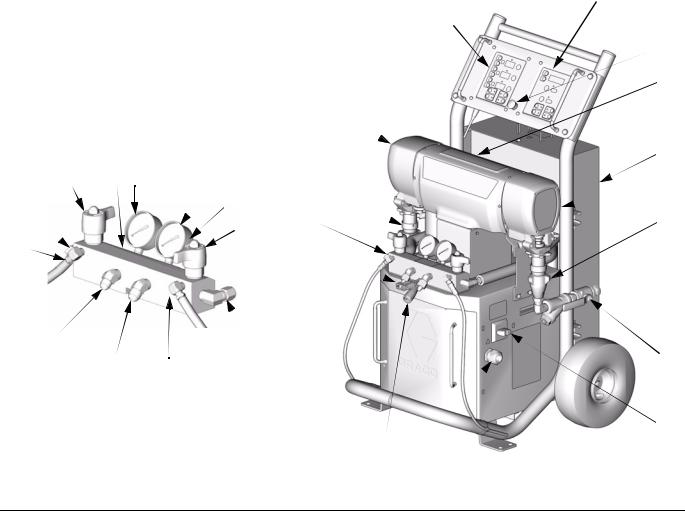
Component Identification
Component Identification
Key for FIG. 3
BA |
Component A Pressure Relief Outlet |
DG |
Drive Gear Housing |
BB |
Component B Pressure Relief Outlet |
EC |
Electrical Cord Strain Relief |
FA |
Component A Fluid Manifold Inlet (behind manifold block) |
EM |
Electric Motor |
FB |
Component B Fluid Manifold Inlet |
FH |
Fluid Heaters (behind shroud) |
GA |
Component A Pressure Gauge |
FM |
Reactor Fluid Manifold |
GB |
Component B Pressure Gauge |
FV |
Fluid Inlet Valve (B side shown) |
HA |
Component A Hose Connection |
HC |
Heated Hose Electrical Connector |
HB |
Component B Hose Connection |
MC Motor Control Display |
|
PA |
Component A Pump |
MP Main Power Switch |
|
PB |
Component B Pump |
RS |
Red Stop Button |
SA |
Component A PRESSURE RELIEF/SPRAY Valve |
SC |
Fluid Temperature Sensor Cable |
SB |
Component B PRESSURE RELIEF/SPRAY Valve |
TC |
Temperature Control Display |
TA |
Component A Pressure Transducer (behind gauge GA) |
|
|
TB |
Component B Pressure Transducer (behind gauge GB) |
|
|
MC
TC
DG 
Detail of Reactor Fluid Manifold
SA |
TA GA |
PA |
|
GB |
|
|
TB |
|
|
|
|
FA |
|
FM |
|
|
SB |
BA |
|
HC |
HA
HB BB
FB
TI3170
SC
EC
 RS
RS
 EM
EM
 FH
FH
 DG
DG
 PB
PB
FV
 MP
MP
TI3764a-1
FIG. 3: Component Identification
309551H |
9 |

Temperature Controls and Indicators
Temperature Controls and Indicators
Heater Power Indicators |
Heater Displays |
Zone A Arrow Keys |
A |
Heater A On/Off Key |
|
||
Zone B Arrow Keys |
B |
Heater B On/Off Key |
Hose Zone Arrow Keys |
|
Hose Heater On/Off Key |
Actual Temperature Key |
|
°F |
|
Temperature Scale Keys |
|
|
|
|
|
|
°C |
Target Temperature Key
FIG. 4. Temperature Controls and Indicators
10 |
309551H |
Main Power Switch
Located on right side of unit, page 9. Turns Reactor
power ON |
and OFF |
. Does not turn |
heater zones or pumps on. |
|
|
Red Stop Button
Located between temperature control panel and motor
control panel, page 9. Press to shut off motor
and heater zones only. Use main power switch to shut off all power to unit.
Actual Temperature Key/LED
Press  to display actual temperature.
Target Temperature Key/LED
Press  to display target temperature.
Temperature Scale
Keys/LEDs
Press °F or °C to change temperature scale.
Heater Zone On/Off
Keys/LEDs
Press  to turn heater zones on and off. Also clears heater zone diagnostic codes, see page 36.
LEDs are on steady when heater zones are powering up. Begin flashing as heat reaches targets.
 LEDs will also flash if cutback point is reached.
Temperature Controls and Indicators
Temperature Arrow Keys
Press  , then press
  or
or  to adjust temperature settings in 1 degree increments.
Temperature Displays
Show actual temperature or target temperature of heater zones, depending on selected mode. Defaults to actual at startup. Range is 32-190°F (0-88°C) for A and B, 32-180°F (0-82°C) for hose.
Circuit Breakers
 WARNING
Read warnings, page 5.
Located inside Reactor cabinet.
Ref. |
Size |
Component |
|
|
|
CB1 |
50 A |
Hose/Transformer Secondary |
|
|
|
CB2 |
20 A |
Transformer Primary |
|
|
|
CB3 |
25 or 40 A* |
Heater A |
|
|
|
CB4 |
25 or 40 A* |
Heater B |
|
|
|
CB5 |
20 A |
Motor/Pumps |
|
|
|
* Depending on model.
CB1

CB2
TI2514A
CB3
CB4  CB5
CB5
For wiring and cabling, see repair manual.
309551H |
11 |

Motor Controls and Indicators
Motor Controls and Indicators
Pressure/Cycle Display
Pressure Arrow Keys 
Motor ON/OFF Key
ON / OFF
PARK Key
Pressure Key
Cycle Count Key
PARK
PSI/BAR Keys
PSI
BAR
FIG. 5. Motor Controls and Indicators
12 |
309551H |

Motor ON/OFF Key/LED
Press  to turn motor ON and OFF. Also clears some motor control diagnostic codes, see page 36.
PARK Key/LED
Press |
at end of day to cycle component A pump |
to home position, submerging displacement rod. Trigger gun until pump stops. Once parked, motor will automatically shut off.
PSI/BAR Keys/LEDs
Press PSI or BAR to change pressure scale.
Motor Controls and Indicators
Cycle Count Key/LED
Press  to display cycle count.
 To clear counter, press and hold
  for 3 sec.
Pressure Arrow Keys
Press  or
or  to adjust fluid pressure when motor is ON. Setpoint displays for 10 sec.
When motor is OFF, pressing  will enter jog mode.
To exit jog mode, press  until display shows dashes or current pressure.
Pressure Key/LED
Press  to display fluid pressure.
 If pressures are imbalanced, display shows higher of two pressures.
Pressure/Cycle Display
Shows fluid pressure or cycle count, depending on mode selected.
Displays J 1 through J 10 when in jog mode, page 35.
309551H |
13 |
Loading...