


24E322
Table of contents
 Loading...
Graco Inc. 24E322, 24E323, 24E324, 24E485, 24E486 Instructions - Parts
...
Instructions - Parts List
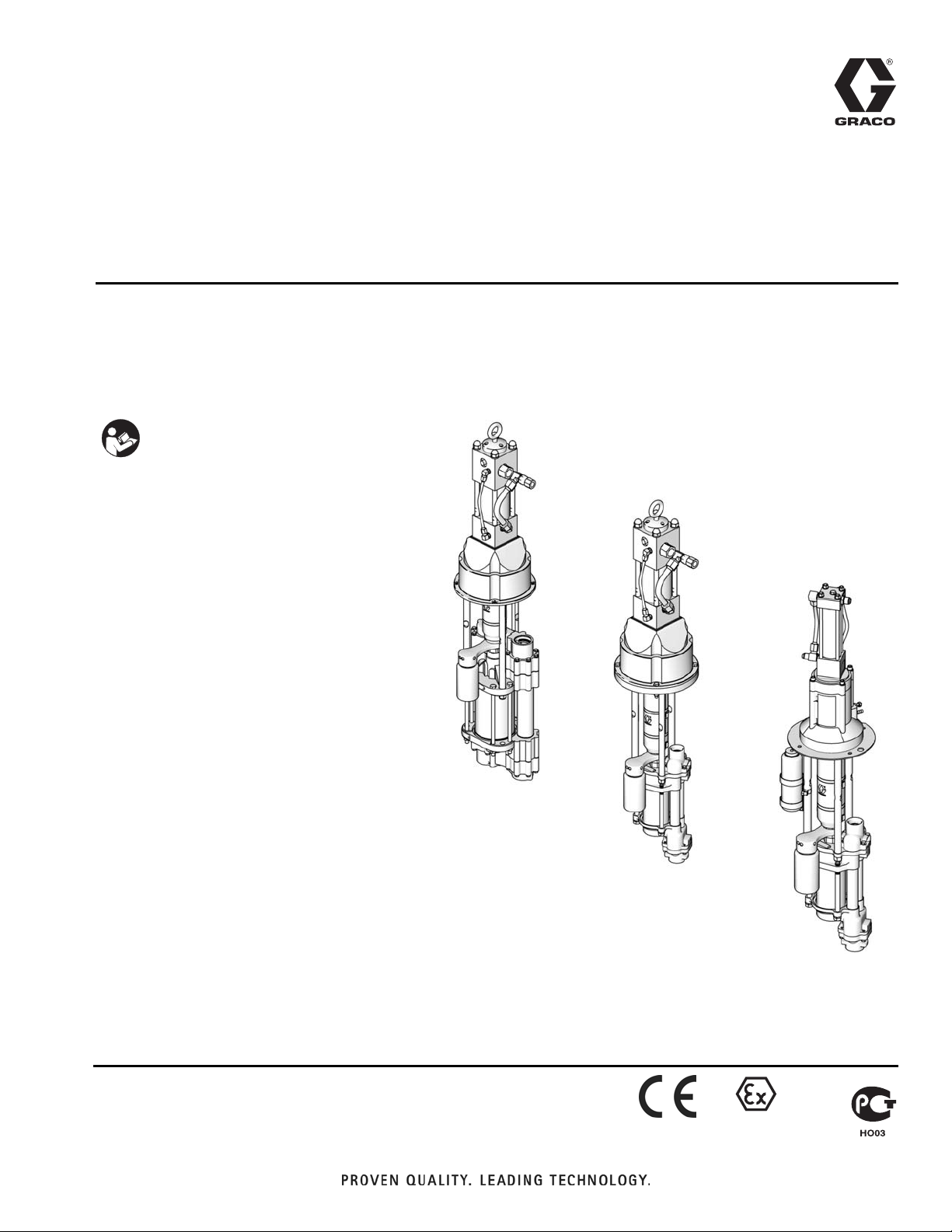
Viscount
®
High-Flo
®
3A0537B
4-Ball Pumps
Hydraulic-powered pumps for low pressure, high volume circulation of finishing materials.
Do not use for flushing or purging lines with caustics, acids, abrasive line strippers, and
other similar fluids. For professional use only.
Important Safety Instructions
Read all warnings and instructions in
this manual. Save these instructions.
See page 3 for model information, including
maximum working pressure and approvals.
US Patent Pending
ENG
TI15609a
Viscount II
High-Flo Pump
with 4000cc
4-Ball Lower
TI15600a
Viscount II
High-Flo Pump
with 2000cc
4-Ball Lower
TI15601a
Viscount I Plus
High-Flo Pump
with 1000cc
4-Ball Lower
II 2 G

Related Manuals
Contents
Related Manuals . . . . . . . . . . . . . . . . . . . . . . . . . . . 2
Models . . . . . . . . . . . . . . . . . . . . . . . . . . . . . . . . . . . 3
High-Flo Pumps with 750cc, 1000cc, 1500cc, or
2000cc Lowers . . . . . . . . . . . . . . . . . . . . . . . 3
High-Flo Pumps with 3000cc or 4000cc Lowers . 3
Warnings . . . . . . . . . . . . . . . . . . . . . . . . . . . . . . . . . 4
Installation . . . . . . . . . . . . . . . . . . . . . . . . . . . . . . . . 6
Grounding . . . . . . . . . . . . . . . . . . . . . . . . . . . . . . 6
Stand Mount . . . . . . . . . . . . . . . . . . . . . . . . . . . . 7
Wall Mount . . . . . . . . . . . . . . . . . . . . . . . . . . . . . 7
Plumbing . . . . . . . . . . . . . . . . . . . . . . . . . . . . . . . 7
Flush Before Using Equipment . . . . . . . . . . . . . . 7
Accessories . . . . . . . . . . . . . . . . . . . . . . . . . . . . . 8
Operation . . . . . . . . . . . . . . . . . . . . . . . . . . . . . . . . 11
Pressure Relief Procedure . . . . . . . . . . . . . . . . 11
Prime the Pump . . . . . . . . . . . . . . . . . . . . . . . . 11
Stop the Pump at the Bottom of Its Stroke . . . . 11
Shutdown . . . . . . . . . . . . . . . . . . . . . . . . . . . . . 11
Maintenance . . . . . . . . . . . . . . . . . . . . . . . . . . . . . . 12
Preventive Maintenance Schedule . . . . . . . . . . 12
Flushing . . . . . . . . . . . . . . . . . . . . . . . . . . . . . . 12
Mix Tank Volume . . . . . . . . . . . . . . . . . . . . . . . . 12
Hydraulic Power Supply Check . . . . . . . . . . . . . 12
Stall Test . . . . . . . . . . . . . . . . . . . . . . . . . . . . . . 12
Changing the TSL . . . . . . . . . . . . . . . . . . . . . . . 13
Troubleshooting . . . . . . . . . . . . . . . . . . . . . . . . . . . 14
Repair . . . . . . . . . . . . . . . . . . . . . . . . . . . . . . . . . . . 15
Disassembly . . . . . . . . . . . . . . . . . . . . . . . . . . . 15
Reassembly . . . . . . . . . . . . . . . . . . . . . . . . . . . . 15
Reassemble the Coupling Adapter and
Tie Rods to the Motor . . . . . . . . . . . . . . . . . 17
Parts . . . . . . . . . . . . . . . . . . . . . . . . . . . . . . . . . . . . 18
Viscount I Plus High-Flo Pumps with 750cc,
1000cc, 1500cc, or 2000cc 4-Ball Lowers . 18
Viscount II High-Flo Pumps with 2000cc Lower 19
Viscount II High-Flo Pumps with 3000cc or
4000 cc Lowers . . . . . . . . . . . . . . . . . . . . . . 20
Dimensions . . . . . . . . . . . . . . . . . . . . . . . . . . . . . . . 21
Motor Mounting Hole Diagrams . . . . . . . . . . . . . . 22
Mounting Stand Hole Layouts . . . . . . . . . . . . . . . 22
255143 Wall Mount Bracket . . . . . . . . . . . . . . . . . . 23
Technical Data . . . . . . . . . . . . . . . . . . . . . . . . . . . . 24
750, 1000, 1500, and 2000cc Pumps with
Viscount I Plus Motor . . . . . . . . . . . . . . . . . 24
2000cc Pumps with Viscount II Motor . . . . . . . . 25
3000 and 4000cc Pumps with
Viscount II Motor . . . . . . . . . . . . . . . . . . . . . 25
Performance Charts . . . . . . . . . . . . . . . . . . . . . . . . 26
Graco Standard Warranty . . . . . . . . . . . . . . . . . . . 30
Related Manuals
Part No. Description
308330 Viscount I Plus Hydraulic Motor manual
308048 Viscount II Hydraulic Motor manual
3A0539 4-Ball Lower manual (750cc, 1000cc,
1500cc, and 2000cc)
3A0540 4-Ball Lower manual (3000cc and 4000cc)
2 3A0537B

Models
High-Flo Pumps with 750cc, 1000cc, 1500cc, or 2000cc Lowers
Maximum Pump
Working Pressure
Model No. Series
24E322 A 450 (3.1, 31.0) 750cc Viscount I Plus npt cst
24E323 A 450 (3.1, 31.0) 750cc Viscount I Plus tri-clamp sst Chromex Chrome
24E324 A 450 (3.1, 31.0) 750cc Viscount I Plus tri-clamp sst Chromex
24E485 A 450 (3.1, 31.0) 750cc Viscount I Plus npt sst Chromex Chrome
24E486 A 450 (3.1, 31.0) 750cc Viscount I Plus npt sst Chromex MaxLife
24E325 A 300 (2.1, 21.0) 1000cc Viscount I Plus npt cst Chromex Chrome
24E326 A 300 (2.1, 21.0) 1000cc Viscount I Plus tri-clamp sst Chromex Chrome
24E327 A 300 (2.1, 21.0) 1000cc Viscount I Plus tri-clamp sst Chromex MaxLife
24E487 A 300 (2.1, 21.0) 1000cc Viscount I Plus npt sst Chromex Chrome
24E488 A 300 (2.1, 21.0) 1000cc Viscount I Plus npt sst Chromex MaxLife
24E328 A 225 (1.6, 16.0) 1500cc Viscount I Plus npt cst Chromex Chrome
24E329 A 225 (1.6, 16.0) 1500cc Viscount I Plus tri-clamp sst Chromex Chrome
24E330 A 225 (1.6, 16.0) 1500cc Viscount I Plus tri-clamp sst Chromex MaxLife
24E489 A 225 (1.6, 16.0) 1500cc Viscount I Plus npt sst Chromex Chrome
24E490 A 225 (1.6, 16.0) 1500cc Viscount I Plus npt sst Chromex MaxLife
24E331 A 167 (1.2, 12.0) 2000cc Viscount I Plus npt cst Chromex Chrome
24E332 A 167 (1.2, 12.0) 2000cc Viscount I Plus tri-clamp sst Chromex Chrome
24E333 A 167 (1.2, 12.0) 2000cc Viscount I Plus tri-clamp sst Chromex MaxLife
24E491 A 167 (1.2, 12.0) 2000cc Viscount I Plus npt sst Chromex Chrome
24E492 A 167 (1.2, 12.0) 2000cc Viscount I Plus npt sst Chromex MaxLife
24E334 A 460 (3.2, 32.0) 2000cc Viscount II npt cst Chromex Chrome
24E335 A 460 (3.2, 32.0) 2000cc Viscount II tri-clamp sst Chromex Chrome
24E336 A 460 (3.2, 32.0) 2000cc Viscount II tri-clamp sst Chromex MaxLife
24E493 A 460 (3.2, 32.0) 2000cc Viscount II npt sst Chromex Chrome
24E494 A 460 (3.2, 32.0) 2000cc Viscount II npt sst Chromex MaxLife
psi (MPa, bar) Lower Size Motor
Connection
Style Material
Rod
Material
Chromex
Cylinder
Material
™
MaxLife
Models
Nitride
®
High-Flo Pumps with 3000cc or 4000cc Lowers
Maximum Pump
Working Pressure
Model No. Series
24E337 A 400 (2.8, 28.0) 3000cc Viscount II npt cst Chromex Chrome
24E338 A 400 (2.8, 28.0) 3000cc Viscount II npt sst Chromex Chrome
24E339 A 400 (2.8, 28.0) 3000cc Viscount II npt sst Chromex MaxLife
24E340 A 300 (2.1, 21.0) 4000cc Viscount II npt cst Chromex Chrome
24E341 A 300 (2.1, 21.0) 4000cc Viscount II npt sst Chromex Chrome
24E342 A 300 (2.1, 21.0) 4000cc Viscount II npt sst Chromex MaxLife
3A0537B 3
psi (MPa, bar) Lower Size Motor
Connection
Style Material
Rod
Material
Cylinder
Material
Warnings
Warnings
The following warnings are for the setup, use, grounding, maintenance, and repair of this equipment. The exclamation point symbol alerts you to a general warning and the hazard symbols refer to procedure-specific risks. When
these symbols appear in the body of this manual, refer back to these Warnings. Product-specific hazard symbols and
warnings not covered in this section may appear throughout the body of this manual where applicable.
WARNING
WARNINGWARNINGWARNING
FIRE AND EXPLOSION HAZARD
Flammable fumes, such as solvent and paint fumes, in work area can ignite or explode. To help prevent
fire and explosion:
• Use equipment only in well ventilated area.
• Eliminate all ignition sources; such as pilot lights, cigarettes, portable electric lamps, and plastic drop
cloths (potential static arc).
• Keep work area free of debris, including solvent, rags and gasoline.
• Do not plug or unplug power cords, or turn power or light switches on or off when flammable fumes are
present.
• Ground all equipment in the work area. See Grounding instructions.
• Use only grounded hoses.
• Hold gun firmly to side of grounded pail when triggering into pail.
• If there is static sparking or you feel a shock, stop operation immediately. Do not use equipment until
you identify and correct the problem.
• Keep a working fire extinguisher in the work area.
Static charge may build up on plastic parts during cleaning and could discharge and ignite flammable
vapors. To help prevent fire and explosion:
• Clean plastic parts only in a well ventilated area.
• Do not clean with a dry cloth.
• Do not operate electrostatic guns in equipment work area.
PRESSURIZED EQUIPMENT HAZARD
Fluid from the gun/dispense valve, leaks, or ruptured components can splash in the eyes or on skin and
cause serious injury.
• Follow the Pressure Relief Procedure when you stop spraying and before cleaning, checking, or
servicing equipment.
• Tighten all fluid connections before operating the equipment.
• Check hoses, tubes, and couplings daily. Replace worn or damaged parts immediately.
TOXIC FLUID OR FUMES HAZARD
Toxic fluids or fumes can cause serious injury or death if splashed in the eyes or on skin, inhaled, or
swallowed.
• Read MSDSs to know the specific hazards of the fluids you are using.
• Store hazardous fluid in approved containers, and dispose of it according to applicable guidelines.
4 3A0537B
Warnings
WARNING
WARNINGWARNINGWARNING
PERSONAL PROTECTIVE EQUIPMENT
You must wear appropriate protective equipment when operating, servicing, or when in the operating area
of the equipment to help protect you from serious injury, including eye injury, hearing loss, inhalation of
toxic fumes, and burns. This equipment includes but is not limited to:
• Protective eyewear, and hearing protection.
• Respirators, protective clothing, and gloves as recommended by the fluid and solvent manufacturer.
EQUIPMENT MISUSE HAZARD
Misuse can cause death or serious injury.
• Do not operate the unit when fatigued or under the influence of drugs or alcohol.
• Do not exceed the maximum working pressure or temperature rating of the lowest rated system
component. See Technical Data in all equipment manuals.
• Use fluids and solvents that are compatible with equipment wetted parts. See Technical Data in all
equipment manuals. Read fluid and solvent manufacturer’s warnings. For complete information about
your material, request MSDS from distributor or retailer.
• Do not leave the work area while equipment is energized or under pressure. Turn off all equipment and
follow the Pressure Relief Procedure when equipment is not in use.
• Check equipment daily. Repair or replace worn or damaged parts immediately with genuine
manufacturer’s replacement parts only.
• Do not alter or modify equipment.
• Use equipment only for its intended purpose. Call your distributor for information.
• Route hoses and cables away from traffic areas, sharp edges, moving parts, and hot surfaces.
• Do not kink or over bend hoses or use hoses to pull equipment.
• Keep children and animals away from work area.
• Comply with all applicable safety regulations.
MOVING PARTS HAZARD
Moving parts can pinch, cut or amputate fingers and other body parts.
• Keep clear of moving parts.
• Do not operate equipment with protective guards or covers removed.
• Pressurized equipment can start without warning. Before checking, moving, or servicing equipment,
follow the Pressure Relief Procedure and disconnect all power sources.
3A0537B 5
Installation
Installation
Grounding
The equipment must be grounded. Grounding
reduces the risk of static and electric shock by
providing an escape wire for the electrical current
due to static build up or in the event of a short circuit.
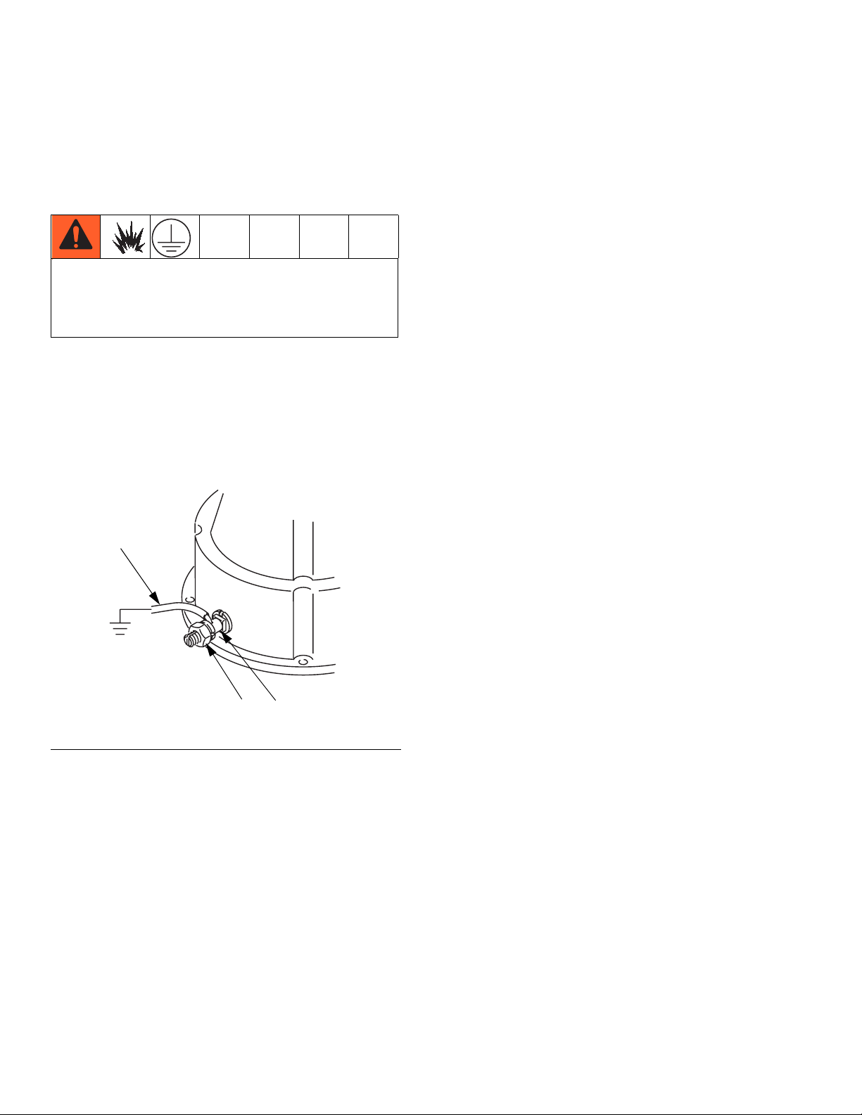
Pump: use a ground wire and clamp. See FIG. 1.
Loosen the locknut (W) of the grounding lug (Z). Insert
one end of the wire (Y) in the ground lug and tighten the
locknut securely. Connect the ground clamp to a true
earth ground. Order Part No. 237569, Ground Wire and
Clamp.
Y
Air and fluid hoses: use only electrically conductive
hoses with a maximum of 500 ft. (150 m) combined
hose length to ensure grounding continuity. Check the
electrical resistance of hoses. If total resistance to
ground exceeds 25 megohms, replace hose immediately.
Hydraulic power supply: follow manufacturer’s recommendations.
Surge tank: use a ground wire and clamp.
Dispense valve: ground through a connection to a
properly grounded fluid hose and pump.
Fluid supply container: follow local code.
Object being sprayed: follow local code.
Solvent pails used when flushing: follow local code.
Use only conductive metal pails, placed on a grounded
surface. Do not place the pail on a nonconductive surface, such as paper or cardboard, which interrupts
grounding continuity.
F
IG. 1 Ground Wire
W
To maintain grounding continuity when flushing or
relieving pressure: hold metal part of the spray gun
firmly to the side of a grounded metal pail, then trigger
the gun.
TI15854a
Z
6 3A0537B

Installation
Stand Mount
Mount the pump in the accessory pump stand (B). Use
Part No. 253692 Stand for 750, 1000, 1500, and 2000cc
Pumps (see F
for 3000 and 4000cc Pumps (see F
See Mounting Stand Hole Layouts on page 22.
Secure the stand to the floor with M19 (5/8 in.) bolts
which engage at least 152 mm (6 in.) into the concrete
floor to prevent the pump from tipping.
IG. 2, page 9) and Part No. 218742 Stand
IG. 3, page 10).
Wall Mount
1. Ensure the wall is strong enough to support the
weight of the pump assembly and accessories, fluid,
hoses, and stress caused during pump operation.
2. Ensure that the mounting location has sufficient
clearance for easy operator access.
3. Position the wall bracket at a convenient height,
ensuring that there is sufficient clearance for the
fluid suction line and for servicing the lower.
Plumbing
Install a fluid shutoff valve (D) between the mix tank (A)
and the pump.
When using a stainless steel pump, use stainless steel
plumbing to maintain a corrosion-resistant system.
Flush Before Using Equipment
The equipment was tested with lightweight oil, which is
left in the fluid passages to protect parts. To avoid contaminating your fluid with oil, flush the equipment with a
compatible solvent before using the equipment. See
Flushing, page 12.
4. Drill four 7/16 in. (11 mm) holes using the bracket as
a template. Use any of the three mounting hole
groupings in the bracket. See 255143 Wall Mount
Bracket, page 23.
5. Bolt the bracket securely to the wall using bolts and
washers designed to hold in the wall’s construction.
6. Attach the pump assembly to the mounting bracket.
7. Connect air and fluid hoses.
3A0537B 7

Installation
Accessories
Install the following accessories in the order shown in
F
IG. 2, using adapters as necessary.
Hydraulic Power Supply
NOTICE
The hydraulic power supply must be kept clean at all
times to avoid damage to the motor and hydraulic
power supply.
1. Blow out hydraulic lines with air and flush thoroughly before connection to the motor.
2. Plug hydraulic inlets, outlets, and line ends when
disconnecting them for any reason.
Be sure the power supply can provide sufficient power to
the motor. Be sure the power supply is equipped with a
suction filter to the hydraulic pump.
Hydraulic Supply Line
• For Viscount I Plus motors, the hydraulic inlet on the
motor is 3/4 in., 37° flare. Use a minimum 1/2 in. (13
mm) ID hydraulic supply line (L).
• For Viscount II motors, use a minimum 13 mm (1/2
in.) ID supply line (L). The motor has a 3/4 npt(f)
hydraulic oil supply fitting.
• For Viscount II motors, use a minimum 22 mm (7/8
in.) ID return line (K). The motor has a 1 in. npt(f)
hydraulic oil return fitting.
• Return line shutoff valve (R): isolates the motor
when servicing the system.
NOTICE
To avoid damage to the pump, never use the return
line shutoff valve to control the hydraulic flow. Do not
install any flow control devices on the hydraulic return
line.
• Return fluid filter (J): removes residue from the
hydraulic fluid to help keep the system running
smoothly (10 micron size).
Fluid Line
For typical installation, see FIG. 2 on page 9.
• Fluid filter: with a 60 mesh (250 micron) stainless
steel element to filter particles from the fluid as it
leaves the pump.
• Fluid drain valve (U): required in your system, to
relieve fluid pressure in the hose and gun.
• Fluid shutoff valve (D): shuts off fluid flow.
• Supply line shutoff valve (S): isolates the motor
when servicing the system.
• Hydraulic fluid pressure gauge (P): monitors the
hydraulic oil pressure to the motor to avoid overpressurizing the motor or lower.
• Pressure- and temperature-compensated flow
control valve (T): prevents the motor from running
too fast, which can damage it.
• Pressure reducing valve (N), which has a drain
line (M) running to the return line (K): controls the
hydraulic pressure to the motor.
Hydraulic Return Line
• For Viscount I Plus motors, the hydraulic outlet on
the motor is 7/8 in., 37° flare. Use a minimum 5/8 in.
(16 mm) ID hydraulic return line (K).
8 3A0537B

Installation
K
L
E
R
N P S
Y
M
T
E
J
A
B
U
G
D
D
U
C
D
FIG. 2. Typical Installation for 750, 1000, 1500, and 2000cc Pumps (Viscount I Plus Motor Shown)
Key:
AMix Tank
B 253692 Pump Stand
C Fluid Supply Line; 1-1/2 in. (38 mm) minimum diameter
D Fluid Shutoff Valve
E Fluid Line; 1 in. (25 mm) minimum diameter
F Surge Tank Stand
G Surge Tank
J 10 Micron Return Filter
K Hydraulic Return Line
L Hydraulic Supply Line
MDrain Line
N Pressure Reducing Valve
P Hydraulic Pressure Gauge
R Return Line Shutoff Valve
S Supply Line Shutoff Valve
T Flow Control Valve
U Fluid Drain Valve (required)
Y Ground Wire (required see page 6 for installation)
F
TI15855a
3A0537B 9
Loading...