


 Loading...
Graco Inc. 255348, 255349, 255350, 255802, 255803 INSTRUCTIONS
...INSTRUCTIONS
SDM5 & SDM15 (Manual);
SDP5 & SDP15 (Preset)
Meters
312865G
ENG
For metered dispense of oils and 50:50 antifreeze/water mix fluids. For professional use only.
Not for use in explosive atmospheres.
Maximum Working Pressure: 1500 psi (10 MPa, 103 bar)
Maximum Working Pressure (50:50 antifreeze/water mix): 900 psi (6.2 MPa, 62 bar)
Maximum Flow Rate:14 gpm (53 lpm)
List of Models page 2
Preset Meter shown
Important Safety Instructions
 Read all warnings and instructions in this manual. Save these instructions.
NOTICE
This dispense valve is designed to dispense petroleum-based lubricants and antifreeze only. Do not dispense windshield washer solvent with this dispense valve.
ti11821
US Patent No: D594,490S
India Patent No: 219652
Korea Patent No: 30-555779
Taiwan Patent No: D130836
Models
Models
SDM5 Manual Dispense Electronic Meters
Model |
|
|
|
|
Number |
Swivel |
Extension Description |
Nozzle |
Fluid Type |
|
|
|
|
|
255348 |
1/2” npt(f) |
Flexible Extension |
Automatic, non-drip, quick close |
Oil |
|
|
|
|
|
255349 |
1/2” npt(f) |
Gear Lube Extension |
None-drip, quick close |
Gear Lube |
|
|
|
|
|
255350 |
1/2” npt(f) |
Rigid Extension |
Automatic, non-drip, quick close |
Oil |
|
|
|
|
|
255802 |
1/2” npt(f) |
Rigid Extension |
Automatic, non-drip, quick close |
Anti-freeze |
|
|
|
|
|
255803 |
1/2” npt(f) |
Flexible Extension |
Automatic, non-drip, quick close |
Anti-freeze |
|
|
|
|
|
SDM15 Manual Dispense Electronic Meters
Model |
|
|
|
|
Number |
Swivel |
Extension Description |
Nozzle |
Fluid Type |
|
|
|
|
|
255800 |
3/4” npt(f) |
Rigid Extension |
Automatic, non-drip, quick close |
Oil |
|
|
|
|
|
255801 |
3/4” npt(f) |
Flexible Extension |
Automatic, non-drip, quick close |
Oil |
|
|
|
|
|
255836 |
1/2” npt(f) |
Rigid Extension |
Automatic, non-drip, quick close |
Oil |
|
|
|
|
|
255837 |
1/2 npt(f) |
Flexible Extension |
Automatic, non-drip, quick close |
Oil |
|
|
|
|
|
SDP5 Preset Dispense Electronic Meters
Model |
|
|
|
|
Number |
Swivel |
Extension Description |
Nozzle |
Fluid Type |
|
|
|
|
|
255200 |
1/2” npt(f) |
Rigid Extension |
Automatic, non-drip, quick close |
Oil |
|
|
|
|
|
255351 |
1/2” npt(f) |
Flexible Extension |
Automatic, Non-drip, quick close |
Oil |
|
|
|
|
|
255352 |
1/2” npt(f) |
Gear Lube Extension |
Non-drip, quick close |
Gear Lube |
|
|
|
|
|
255355 |
1/2” npt(f) |
Rigid Extension |
Automatic, non-drip, quick close |
Anti-freeze |
|
|
|
|
|
255356 |
1/2” npt(f) |
Flexible Extension |
Automatic, non-drip, quick close |
Anti-freeze |
|
|
|
|
|
2 |
312865G |
|
|
|
|
Models |
SDP15 Preset Dispense Electronic Meters |
|
|||
|
|
|
|
|
Model |
|
|
|
|
Number |
Swivel |
Extension Description |
Nozzle |
Fluid Type |
|
|
|
|
|
255353 |
3/4” npt(f) |
Rigid Extension |
Automatic, non-drip, quick close |
Oil |
|
|
|
|
|
255354 |
3/4” npt(f) |
Flexible Extension |
Automatic, non-drip, quick close |
Oil |
|
|
|
|
|
256838 |
1/2” npt(f) |
Rigid Extension |
Automatic, non-drip, quick close |
OIl |
|
|
|
|
|
256839 |
1/2” npt(f) |
Flexible Extension |
Automatic, non-drip, quick close |
Oil |
|
|
|
|
|
312865G |
3 |
Warnings
Warnings
The following warnings are for the setup, use, grounding, maintenance, and repair of this equipment. The exclamation point symbol alerts you to a general warning and the hazard symbol refers to procedure-specific risk. Refer back to these warnings. Additional, product-specific warnings may be found throughout the body of this manual where applicable.
 WARNING
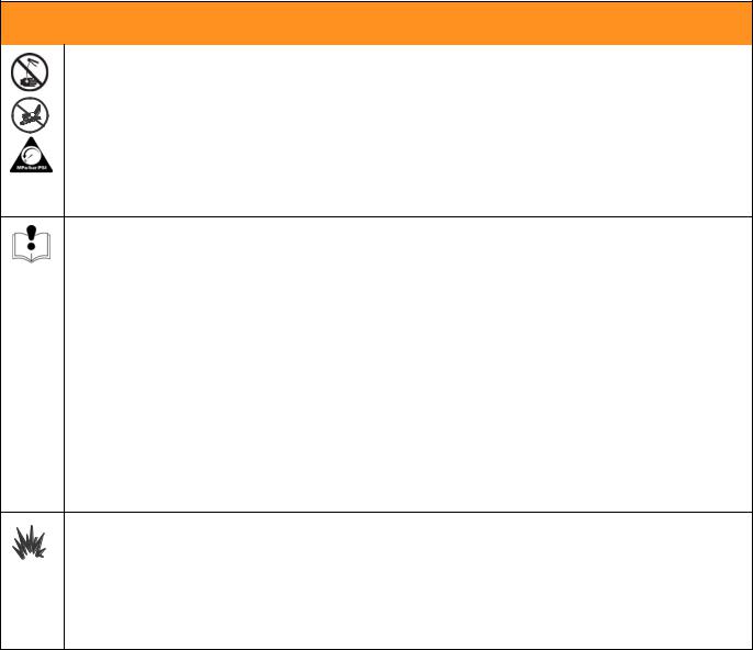
SKIN INJECTION HAZARD
High-pressure fluid from dispense valve, hose leaks, or ruptured components will pierce skin. This may look like just a cut, but it is a serious injury that can result in amputation. Get immediate surgical treatment.
•Do not point dispense valve at anyone or at any part of the body.
•Do not put your hand over the end of the dispense nozzle.
•Do not stop or deflect leaks with your hand, body, glove, or rag.
•Follow Pressure Relief Procedure in this manual, when you stop spraying and before cleaning, checking, or servicing equipment.
EQUIPMENT MISUSE HAZARD
Misuse can cause death or serious injury.
•Do not operate the unit when fatigued or under the influence of drugs or alcohol.
•Do not exceed the maximum working pressure or temperature rating of the lowest rated system component. See Technical Data in all equipment manuals.
•Use fluids and solvents that are compatible with equipment wetted parts. See Technical Data in all equipment manuals. Read fluid and solvent manufacturer’s warnings. For complete information about your material, request MSDS forms from distributor or retailer.
•Check equipment daily. Repair or replace worn or damaged parts immediately with genuine manufacturer’s replacement parts only.
•Do not alter or modify equipment.
•Use equipment only for its intended purpose. Call your distributor for information.
•Route hoses and cables away from traffic areas, sharp edges, moving parts, and hot surfaces.
•Do not kink or over bend hoses or use hoses to pull equipment.
•Keep children and animals away from work area.
•Comply with all applicable safety regulations.
BATTERY SAFETY
The battery may leak, explode, cause burns, or cause an explosion if mishandled:
•You must use the battery type specified for use with the equipment.
•Sparking can occur when changing batteries. Only replace the battery in a non-hazardous location, away from flammable fluids or fumes.
•Handle and dispose of battery properly - do not short circuit, charge, force over discharge, disassemble, crush, penetrate, incinerate, or heat the battery to a temperature exceeding 185° F (85° C).
4 |
312865G |

Warnings
 WARNING
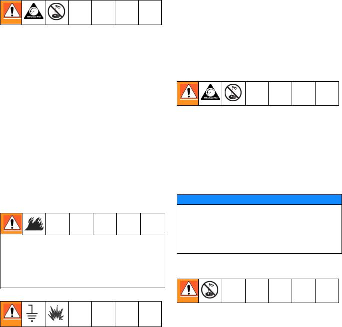
FIRE AND EXPLOSION HAZARD
When flammable fluids are present in the work area, such as gasoline and windshield wiper fluid, be aware that flammable fumes can ignite or explode. To help prevent fire and explosion:
•Use equipment only in well ventilated area.
•Eliminate all ignition sources, such as cigarettes and portable electric lamps.
•Keep work area free of debris, including rags and spilled or open containers of solvent and gasoline.
•Do not plug or unplug power cords or turn lights on or off when flammable fumes are present.
•Ground all equipment in the work area.
•Use only grounded hoses.
•If there is static sparking or you feel a shock, stop operation immediately. Do not use equipment until you identify and correct the problem.
•Keep a working fire extinguisher in the work area.
312865G |
5 |

Installation
Installation
Typical Installations (FIG. 1)
The typical installation shown in FIG. 1 is only a guide. It is not a complete system design. Contact your Graco distributor for assistance in designing a system to suit your needs.
NOTICE
The dispense valve is not designed for in-line installation. Do not install with a shutoff valve on the outlet side of the meter. Such installation could result in damage to the meter housing cover.
B
 D
D
 E
E
 C
C
A
ti11010a
FIG. 1
ITEM DESCRIPTION
AElectronic metered dispense valve
BFluid shut-off valve
CHose
DHose reel fluid inlet hose
EHose reel
A Thermal Relief Kit (not shown) is required. The kit required will vary by pump selected. See Parts, page 40 for a list of available kits.
Mounting Bracket (FIG. 2)
Mounting Bracket Kit 249440 is available for resting the dispense valve on a console.
ti11822
FIG. 2
Drum Mount Bracket (FIG. 3)
Mounting Bracket 15B750 is available for resting the dispense valve on a drum.
ti11823
FIG. 3
6 |
312865G |
Pressure Relief Procedure
This equipment will stay pressurized until the pressure has been manually relieved. To reduce the risk of serious injury from pressurized fluid, accidental spray from the dispense valve or splashing fluid, follow this
Pressure Relief Procedure when ever you:
•Are instructed to relieve pressure.
•Check, clean or service any system equipment.
•Install or clean fluid nozzles or filter.
1.Turn off power supply to the pump or close upstream ball valve.
2.Trigger the dispense valve into a waste container to relieve pressure.
3.Open any bleed-type master air valves and fluid drain valves in the system.
4.Leave the drain valve open until you are ready to pressurize the system.
Grounding
FIRE HAZARD: Conductive metal surfaces on the meter must not make contact with any positively charged metal surface, including (but not limited to), the starter solenoid terminal, alternator terminal or battery terminal. Such contact could cause electrical arcing and a fire.
The equipment must be grounded. Grounding reduces the risk of static and electric shock by providing an escape wire for the electrical current due to static build up or in the event of a short circuit.
Pump: Follow manufacturer’s recommendations.
Air and fluid hoses: Only use electrically conductive hoses. Check electrical resistance of hoses. If total resistance to ground exceeds 29 megohms, replace hose immediately.
Installation
Air compressor: Follow manufacturer’s recommendations.
Fluid supply container: Follow local code.
To maintain grounding continuity when flushing or relieving pressure: hold a metal part of the dispense valve firmly to the side of a grounded metal pail, then trigger the valve.
Pre-Installation Procedure
1.Relieve pressure, page 7.
2.Close the shut-off valve (B, FIG. 1).
3.Ground the hose and reel or console, page 7. Leave at least two threads bare when using PTFE tape. The bare threads ensure a ground is maintained.
Installation Procedure
NOTICE
•If this is a new installation or if the fluid lines are contaminated, flush the lines before you install the metered valve. Contaminated lines could cause the valve to leak.
•Never dispense compressed air with meter. Doing so will damage meter.
Flushing
If this is an existing installation, go to Installing Meter section, page 8. The following procedure, Steps 1-5 are the Flushing Procedure.
1.Close the fluid shut-off valve (B, FIG. 1, page 6) at each dispense position.
2.Make sure:
•main fluid outlet valve at the pump is closed,
•air pressure to the pump motor is adjusted, and
•air valve is open.
312865G |
7 |
Installation
3.Slowly open the main fluid valve.
a.Place the hose end (with no dispense valve connected) into a container for waste oil.
b.Secure the hose in the container so it will not come out during flushing.
c.If you have multiple dispense positions, first flush the dispense position farthest from the pump and work your way toward the pump.
4.Slowly open the shut-off valve (B) at the dispense position. Flush out a sufficient amount of oil to ensure that the entire system is clean; then close the valve.
5.Repeat Step 4 at all other positions.
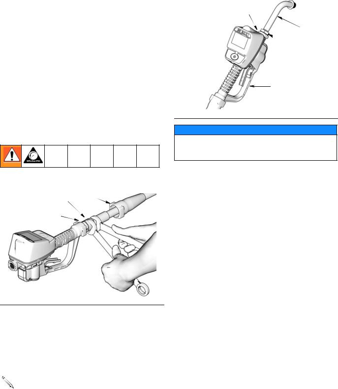
Installing Meter (FIG. 4
)
1. Relieve pressure, page 7.
a |
32 |
|
31
ti10983a
FIG. 4
2.Slide the swivel boot (32) back, over the hose, small end first, to access the swivel fitting (a).
3.Apply thread sealant to the male threads of the hose fitting. Thread the hose fitting into the meter swivel (31). Use two wrenches to tighten securely (FIG. 4).
Make sure you let the sealant cure to the manufac- 
 turer’s recommendations before circulating fluid
through the system.
Installing Tube Extension (FIG. 5)
b
 20
20
 a
a
c
ti10615A
FIG. 5
NOTICE
Do not use PTFE tape or thread sealant on threads of extension tube (20). This could cause the fitting to leak.
1.
a.Loosen nut (a) until it is completely off tube threads.
b.Thread extension (20) into housing (b) until it bottoms out.
c.Align extension (20) with meter housing and handle (c).
d.Firmly tighten nut (a).
8 |
312865G |
Installation
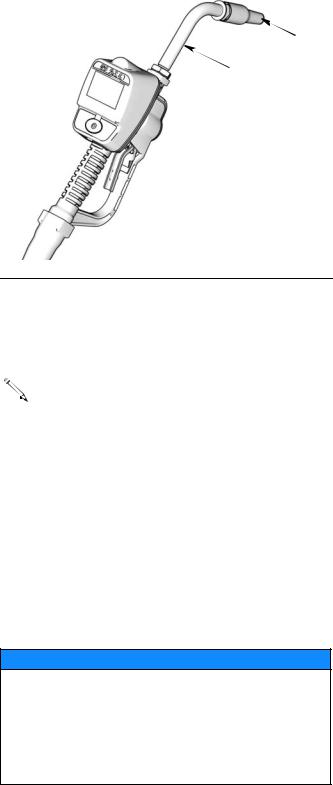
Installing Nozzle (FIG. 6)
 33
33
20
ti10615A
FIG. 6
1.
a.Thread new nozzle (33) onto extension (20).
b.With an open-end adjustable wrench on flats of nozzle bushing, tighten firmly.
• Only tighten nozzle with wrench on flats of the nozzle bushing.
•Do not disassemble the bushing from nozzle. Disassembly will affect performance of the nozzle.
2.Open automatic twist lock nozzle and all fluid shut-off valves. Start pump to pressurize system. See Operation Screens, Dispensing in either the Manual or Preset Mode instructions beginning on page 19 for complete meter operation information.
3.To ensure dispensing accuracy, purge all air from the fluid lines and dispense valve before you use it.
4.Set the system flow to the desired flow rate.
NOTICE
Do not trigger meter when nozzle is closed. Fluid will build up behind the nozzle, leak from the nozzle, and unexpectedly be expelled when the nozzle is opened. If you do accidentally trigger the meter with the nozzle closed, point the nozzle into a waste bucket and open the nozzle to relieve pressure and expel the built up fluid.
312865G |
9 |
Meter Overview
Meter Overview
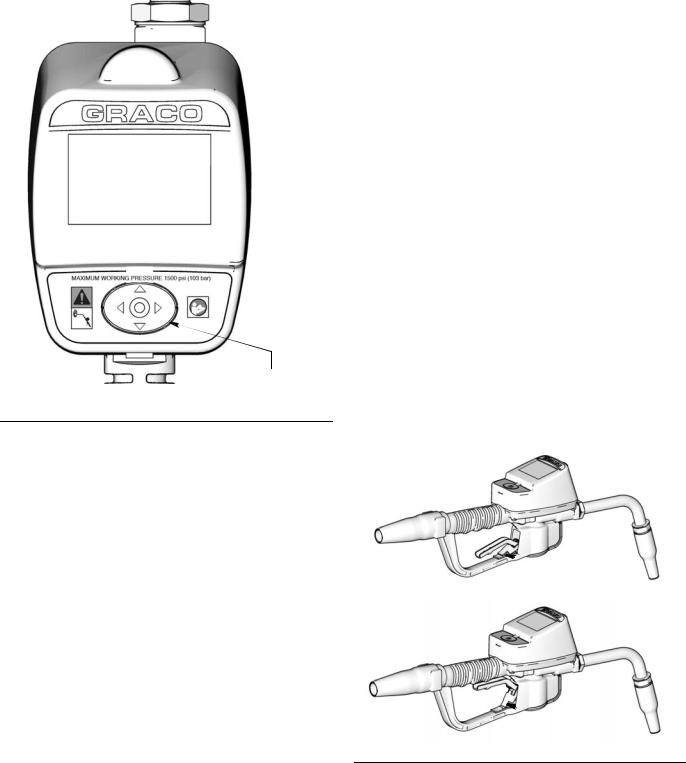
Navigation and Modes
5-Way Menu
ti11824
Navigation Button
FIG. 7
5-Way Menu Navigation Button (FIG. 7)
•Includes 4 direction ARROWS (UP, DOWN, LEFT, RIGHT) and a center, ENTER button.
•Pressing the direction ARROWS allows user to easily scroll through menus. To select/store your selection, you must press the center, ENTER button.
•Pressing and holding a direction ARROW down allows user to scroll through menus quickly.
Meter Display
Adjusting Screen Contrast using ARROWS
On the Setup Home Screen (page 11), use the LEFT and RIGHT ARROWS to adjust the screen contrast.
•Darken the Screen: Press the RIGHT ARROW multiple times.
•Brighten the Screen: Press the LEFT ARROW multiple times.
Asleep/Awake Mode
•Asleep: Battery-saving mode. The display goes blank after 2 minutes of inactivity during normal operation. Unit continues to keep track of amount dispensed while the display is asleep.
•Awake: Display comes awake from sleep mode when you press any ARROW or the ENTER button or when you squeeze the trigger to dispense fluid.
Locking and Unlocking Trigger
The Preset Meters only, include a locking trigger feature that allows the user to lock the trigger in the dispense position as shown in FIG. 8. To release the lock, firmly squeeze the trigger to the handle.
Preset Meters Only
 Unlocked
 Locked
FIG. 8
10 |
312865G |
Setup Mode Screens
Setup Mode Screens
If you are in Operation Mode you must be on the Home Screen shown in FIG. 10, to access the Setup Mode Screens. (A complete description of the Home Screen is provided on page 18).
To display the Home Screen:
1.Wake up the meter by pressing any button on the key pad.
2.When an operation mode screen displays (such as
MOBIL1 5W-20
10.56 QTS
the one shown in FIG. 9):
a.Use the RIGHT ARROW to move the curser over the House icon (a).
b.Press center, ENTER button to display the Home Screen (FIG. 10).
a
ti12179a
FIG. 9
Manual Meters |
Preset Meters |
MOBIL1 5W-20
MANUAL
TOTALS
ti12175a
MOBIL1 5W-20
MANUAL
PRESET
TOTALS
ti12184a
FIG. 10
312865G |
11 |
Setup Mode Screens
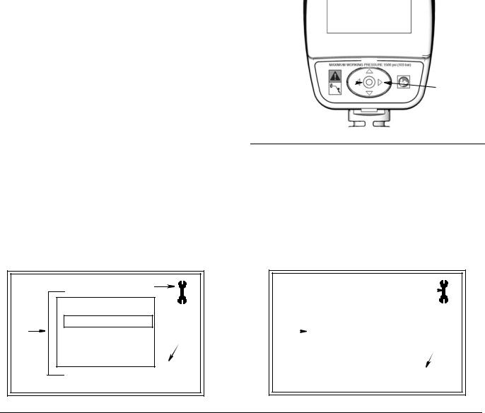
Main Setup Screen (FIG. 12)
All Meters
The Main Setup Screen is the first screen displayed when you enter the Setup Mode. This screen displays a list of the available Setup Screens and also includes a link back to the Home Screen.
Manual Meters Screens:
•UNITS/LIMIT
•CALIBRATE
•BANNER
•LANGUAGE
•HOME
Preset Meters include all the Manual Meter’s Setup Screens and also a PRESET screen.
•UNITS/LIMIT
•CALIBRATE
•PRESET
•BANNER
•LANGUAGE
•HOME
Manual Meters
|
|
A |
|
UNITS/LIMIT |
|
B |
CALIBRATE |
|
BANNER |
1 |
|
|
LANGUAGE |
|
|
|
|
|
HOME |
1.23.45 |
|
|
|
|
|
ti12177a |
FIG. 12 |
|
|
Displaying Setup Screen from an Operation Mode Screen
(b) |
(a) |
|
ti11824a |
FIG. 11
1.Hold down the RIGHT ARROW (a) only, for a few seconds (FIG. 11).
2.Then at the same time, also press the center, ENTER button (b) (FIG. 11). Hold both buttons down until the Main Setup Screen shown in FIG. 12 displays.
Preset Meters
|
|
|
|
|
|
|
|
A |
|
|
|
|
|
|
|
|
|
|
|
|
|||
|
|
|
|
|
|
|
UNITS/LIMIT |
|
|
|
|
B |
|
|
|
|
|
|
CALIBRATE |
|
|
|
|
|
|
|
|
|
PRESET |
|
|
|
|
||
|
|
|
|
|
|
|
|
||||
|
|
|
|
|
|
|
BANNER |
|
1 |
||
|
|
|
|
|
|
|
LANGUAGE |
|
|
|
|
|
|
|
|
|
|
|
HOME |
|
1.23.45 |
|
|
|
|
|
|
|
|
|
|
|
|
|
|
ti12186a
Main Screen Features (FIG. 12)
A. Screen Identifier Icon: Wrench icon displays in the upper right corner when user is on the Main Screen of the Setup screens.
B. Setup Screens: Screens available to user.
1.Use UP or DOWN ARROWS to select a screen from the list.
2.Press center, ENTER button to confirm selection. Selected screen displays.
1. Software Version Number: Reference number. You may be asked to provide this number when contacting Graco for technical support.
12 |
312865G |
Setup Mode Screens
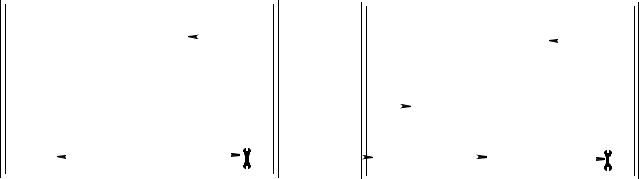
Units/Limit Screen (FIG. 13)
For All Meters
Sets the units of measurement to pints, quarts, liters, or gallons.
|
Manual Meters |
|
Preset Meters |
|
|
|
||||
|
|
|
|
|
|
|
|
|
|
|
|
|
|
|
|
|
|
|
|
|
|
|
|
|
|
|
|
|
|
|
|
|
|
|
|
|
|
|
|
|
|
|
|
|
UNITS = QTS |
|
|
|
|
|
|
|
|
|
|
|
C |
|
UNITS = QTS |
|
C |
||||
|
|
|
|
|||||||
|
|
|||||||||
|
|
|
|
|
|
|
|
|
|
|
|
|
|
|
|
|
G |
|
|
MANUAL LIMIT = 5.0 |
|||||||||
|
|
|
|
|
|
|
|
|
|
|
|
|
|
|
|
|
|
||||||||||||
|
|
|
|
|
|
|
|
|
|
|
|
|
|
|
|
|
|
|
|
|
|
|
|
|
|
|
|
|
|
|
|
|
|
|
|
|
|
|
|
|
|
|
|
|
|
|
|
|
|
|
|
|
|
|
|
|
|
|
|
|
|
|
|
|
|
|
|
|
|
|
|
|
|
|
|
|
|
|
|
|
|
|
|
|
|
|
|
|
|
|
|
|
QTS |
|
|
|
|
|
|
|
|
|
|
|
|
|
|
|
|
|
|
|
|
|
|
|
|
|
|
|
|
E |
D |
E |
|
|
|
QTS |
F |
5.0 |
D |
|
|
|
|
|
|||||||||||||
|
|
|
|
|
|
|
|
|
|
|
|||||||||||||||||||
|
|
|
|
|
|
|
|
|
|
|
|
|
|
|
|
|
|
|
|
|
|
|
|
|
|
|
|
|
|
|
|
|
|
|
|
|
|
|
|
|
|
|
|
|
|
|
|
|
|
|
|
|
|
|
|
|
|
|
|
|
|
|
|
|
|
|
|
|
|
|
|
|
|
|
|
|
|
|
|
|
|
|
|
|
|
|
|
|
|
|
|
|
|
|
|
|
|
|
|
|
|
|
|
|
|
|
|
|
|
|
|
|
|
|
|
|
|
|
|
|
|
|
|
|
|
|
|
|
|
|
|
|
|
|
|
|
|
|
|
|
|
|
|
|
|
|
|
|
|
|
|
|
|
|
|
|
|
|
|
|
|
|
|
|
|
|
|
|
|
|
|
|
|
|
ti12191a |
||||
FIG. 13 |
|
|
|
|
|
|
|
|
|
|
|
|
|
|
|
|
|
|
|
|
|
|
|
|
|
|
|||
|
|
|
|
|
|
|
|
|
|
|
|
|
|
|
|
|
|
|
|
|
|
|
|
|
|
|
|
|
|
Units/Limit Screen Features (FIG. 13) |
|
|
|
|
|
|
|
|
|
|
|
|
|
|
|
|
|
|
|||||||||||
All meters include C - E |
|
|
|
|
|
Preset meters also include F - G |
|
|
|
|
|
|
|||||||||||||||||
C. Units Mode: Displays measurement unit that was |
F. Set Manual Dispense Limit field: Sets maximum |
||||||||||||||||||||||||||||
selected using the Set Measurement Units |
quantity of fluid that can be dispensed in Manual Mode. |
||||||||||||||||||||||||||||
button (E). |
|
|
|
|
|
|
|
|
|
|
|
|
|
|
|
|
|
|
|
|
|
|
|
|
|
|
|||
|
|
|
|
|
|
|
|
|
|
|
|
To change/set the Manual Dispense Limit: |
|||||||||||||||||
D. Wrench Icon: Returns user to Main Setup Screen. |
|
|
|
|
|
|
|
|
|
|
|
|
|
|
|
|
|
|
|||||||||||
|
|
|
|
|
|
|
|
|
|
|
|
1. Use RIGHT ARROW to move curser to Manual Dis- |
|||||||||||||||||
E. Set Measurement Units button/field: Sets unit of |
|
|
pense Limit field (F). |
|
|
|
|
|
|
|
|||||||||||||||||||
measurement as pint, quart, gallon or liter. |
2. Use UP or DOWN ARROWS to increase and |
||||||||||||||||||||||||||||
|
|
|
|
|
|
|
|
|
|
|
|
||||||||||||||||||
To change/set the Unit of Measurement: |
|
|
decrease displayed amount. |
|
|
|
|
|
|
||||||||||||||||||||
1. Use LEFT or RIGHT ARROW to move curser to the |
3. When amount you want to use is shown in field, |
||||||||||||||||||||||||||||
|
|
press center, ENTER button to confirm amount. |
|||||||||||||||||||||||||||
|
|
Set Measurement field (E). |
|
|
|
|
|
|
|
||||||||||||||||||||
|
|
|
|
|
|
|
|
|
Confirmed amount displays on screen (G). |
||||||||||||||||||||
|
|
|
|
|
|
|
|
|
|
|
|
|
|
||||||||||||||||
2. Use UP or DOWN ARROWS to display measure- |
4. When you have finished making changes, use the |
||||||||||||||||||||||||||||
|
|
ment unit choices: PTS, QTS, L, GAL. |
|||||||||||||||||||||||||||
|
|
|
|
RIGHT ARROW button to move curser over Wrench |
|||||||||||||||||||||||||
|
|
|
|
|
|
|
|
|
|
|
|
|
|
||||||||||||||||
3. Press center, ENTER button to confirm selection. |
|
|
icon. |
|
|
|
|
|
|
|
|
|
|
||||||||||||||||
|
|
Selected measurement unit is displayed on screen |
5. |
|
Press center, ENTER button to return to Main Setup |
||||||||||||||||||||||||
|
|
(C). |
|
|
|
|
|
|
|
|
|
||||||||||||||||||
|
|
|
|
|
|
|
|
|
|
|
|
Screen. |
|
|
|
|
|
|
|
|
|
|
|||||||
|
|
|
|
|
|
|
|
|
|
|
|
|
|
|
|
|
|
|
|
|
|
|
|
||||||
4. When you are finished making changes, use the |
G. Manual Limit Confirmation: Displays maximum |
||||||||||||||||||||||||||||
|
|
RIGHT ARROW to move curser over Wrench icon. |
|||||||||||||||||||||||||||
|
|
quantity of fluid that can be manually dispensed at one |
|||||||||||||||||||||||||||
|
|
|
|
|
|
|
|
|
|
|
|
||||||||||||||||||
5. Press center, ENTER button to return to Main Setup |
time. Amount is assigned on the task bar Set Manual |
||||||||||||||||||||||||||||
|
|
Screen. |
|
|
|
|
|
|
|
|
Dispense Limit field (F). Preset dispense amounts are |
||||||||||||||||||
|
|
|
|
|
|
|
|
|
|
|
|
not affected by the manual dispense limit you set. |
|||||||||||||||||
312865G |
13 |
Loading...