


 Loading...
Software Instructions
ProMix® 2KS/3KS Web
Interfaces |
313386D |
EN |
Installation and program setup instructions to allow communication between a PC and the ProMix® 2KS/3KS Electronic Proportioner, via an Ethernet. For professional use only.
Not for use in explosive atmospheres.
Basic Web Interface (supplied with ProMix 2KS/3KS EasyKey software)
Advanced Web Interface Kit 15V337 (Accessory)
Important Safety Instructions |
|
|
Read all warnings and instructions in this manual |
|
|
and in your proportioning system manual. Save |
Advanced Web Interface Module Shown |
|
these instructions. |
||
|
TI12933b
Related Manuals
Contents
Related Manuals . . . . . . . . . . . . . . . . . . . . . . . . . . . 2 Warnings . . . . . . . . . . . . . . . . . . . . . . . . . . . . . . . . . 3 ProMix 2KS/3KS Basic Web Interface (BWI) . . . . . 4
Installation . . . . . . . . . . . . . . . . . . . . . . . . . . . . . . 4 Web Navigation Screens . . . . . . . . . . . . . . . . . . . 8
Install the Advanced Web Interface (AWI) Module 12
Overview . . . . . . . . . . . . . . . . . . . . . . . . . . . . . . 12 Location . . . . . . . . . . . . . . . . . . . . . . . . . . . . . . 12 Mounting . . . . . . . . . . . . . . . . . . . . . . . . . . . . . . 12 Connect Module to EasyKey and PC . . . . . . . . 13
Computer Configuration . . . . . . . . . . . . . . . . . . . . 16
Set up an Automatic IP Address . . . . . . . . . . . . 16 System Initialization . . . . . . . . . . . . . . . . . . . . . 16 Password Recovery . . . . . . . . . . . . . . . . . . . . . 18
Set the Network Configuration . . . . . . . . . . . . . . 19
AWI Screens . . . . . . . . . . . . . . . . . . . . . . . . . . . . . . 21
Network Tab . . . . . . . . . . . . . . . . . . . . . . . . . . . . 21
Materials Tab . . . . . . . . . . . . . . . . . . . . . . . . . . . 22
Settings Tab . . . . . . . . . . . . . . . . . . . . . . . . . . . . 24
System Setup Screens . . . . . . . . . . . . . . . . . . . 26
Replace AWI Board . . . . . . . . . . . . . . . . . . . . . . . . 36
Parts . . . . . . . . . . . . . . . . . . . . . . . . . . . . . . . . . . . . 38
15V337 Advanced Web Interface Module . . . . . 38
15V336 Advanced Web Interface Server Hub . . 39
Electrical Schematic . . . . . . . . . . . . . . . . . . . . . . . 40
Dimensions . . . . . . . . . . . . . . . . . . . . . . . . . . . . . . . 41
Graco Standard Warranty . . . . . . . . . . . . . . . . . . . 42
Graco Information . . . . . . . . . . . . . . . . . . . . . . . . . 42
Related Manuals
Component Manuals in English
Manual |
Description |
|
|
312775 |
ProMix 2KS Manual System Installation |
312776 |
ProMix 2KS Manual System Operation |
|
|
312777 |
ProMix 2KS Manual System Repair-Parts |
|
|
312778 |
ProMix 2KS Automatic System Installation |
|
|
312779 |
ProMix 2KS Automatic System Operation |
|
|
312780 |
ProMix 2KS Automatic System Repair-Parts |
|
|
313881 |
ProMix 3KS Installation (All Systems) |
|
|
313882 |
ProMix 3KS Manual System Operation |
|
|
313883 |
ProMix 3KS Repair-Parts (All Systems) |
|
|
313885 |
ProMix 3KS Automatic System Operation |
312781 |
Fluid Mix Manifold |
312782 |
Dispense Valve |
312783 |
Color Change Valve Stacks |
312787 |
Color Change Module Kit |
312784 |
Gun Flush Box Kits |
310745 |
Gun Air Shutoff Kit |
312786 |
Dump Valve and Third Purge Valve Kits |
|
|
312785 |
Network Communication Kits |
|
|
308778 |
G3000/G3000HR/G250/G250HR Flow Meter |
|
|
310696 |
Coriolis Flow Meter |
|
|
313212 |
Gun Flush Box Integration Kit |
|
|
313290 |
Floor Stand Kit |
|
|
2 |
313386D |

Warnings
Warnings
The following warnings are for the setup, use, grounding, maintenance, and repair of this equipment. The exclamation point symbol alerts you to a general warning and the hazard symbol refers to procedure-specific risk. Refer back to these warnings. Additional, product-specific warnings may be found throughout the body of this manual where applicable.
 WARNING
EQUIPMENT MISUSE HAZARD
Misuse can cause death or serious injury.
•Do not operate the unit when fatigued or under the influence of drugs or alcohol.
•Do not exceed the maximum working pressure or temperature rating of the lowest rated system component. See Technical Data in all equipment manuals.
•Use fluids and solvents that are compatible with equipment wetted parts. See Technical Data in all equipment manuals. Read fluid and solvent manufacturer’s warnings. For complete information about your material, request MSDS forms from distributor or retailer.
•Check equipment daily. Repair or replace worn or damaged parts immediately with genuine manufacturer’s replacement parts only.
•Do not alter or modify equipment.
•Use equipment only for its intended purpose. Call your distributor for information.
•Route hoses and cables away from traffic areas, sharp edges, moving parts, and hot surfaces.
•Do not kink or over bend hoses or use hoses to pull equipment.
•Keep children and animals away from work area.
•Comply with all applicable safety regulations.
ELECTRIC SHOCK HAZARD
Improper grounding, setup, or usage of the system can cause electric shock.
•Turn off and disconnect power at main switch before disconnecting any cables and before servicing equipment.
•Connect only to grounded power source.
•All electrical wiring must be done by a qualified electrician and comply with all local codes and regulations.
313386D |
3 |

ProMix 2KS/3KS Basic Web Interface (BWI)
ProMix 2KS/3KS Basic Web Interface (BWI)
NOTE: Screen views in this manual are shown using Microsoft Windows XP.
NOTE: The ProMix 2KS/3KS Basic Web Interface (BWI) is supplied with all EasyKeys. To run the program, Java Version 6 Update 10 (or later) must be loaded on your computer. This is a free download.
Installation
1.Before connecting your computer to the EasyKey, verify that Java Version 6 Update 10 (or later) is loaded on your computer. To verify, go to Java.com using your Internet browser and click on “Do I Have Java?” for further information.
2.After verifying that Java is loaded on the computer, connect the computer directly to the EasyKey, using the 15G869 CAT5 ethernet crossover cable supplied with the EasyKey. See FIG. 1.
EasyKey
15G869 CAT5 Ethernet Crossover Cable
Computer
TI13102a
EasyKey (Bottom View)
TI12638a
CAT5 Cable Connector
FIG. 1. ProMix 2KS/3KS Basic Web Interface Connection
4 |
313386D |

3.Before running the BWI software you must manually assign an IP address to your computer:
a. On your computer, click on the Start button
to open the menu, then click
on Control Panel |
. |
ProMix 2KS/3KS Basic Web Interface (BWI)
b.See FIG. 2. Double click on Network Connections. Double click on Local Area Connection to open the Local Area Connection Status window. Click on Properties to open the Local Area Connection Properties window. See FIG. 3.
FIG. 2. Assign IP Address on Computer
313386D |
5 |

ProMix 2KS/3KS Basic Web Interface (BWI)
c.In the Local Area Connection Properties window, scroll to Internet Protocol (TCP/IP) and double click, to open the Internet Protocol (TCP/IP) Properties window. See FIG. 4.
FIG. 3: Local Area Connection Properties Window
d.See FIG. 4. Set to “Use the following IP address:”
e.Type in the following IP address: 192.168.178.201
f.Type in the following Subnet mask: 255.255.255.0
FIG. 4: Internet Protocol (TCP/IP) Window
NOTE: To reconnect to the user network, change the setting back to “Obtain an IP Address Automatically.”
g.Click on OK to accept the changes and close the Internet Protocol (TCP/IP) Properties window.
h.Click on OK to close the Local Area Connection Properties window.
i.Close the Local Area Connection Status window and Network Connections window.
6 |
313386D |

|
ProMix 2KS/3KS Basic Web Interface (BWI) |
4. On the EasyKey, go to System Configuration |
• If “ProMix web interface requires Java to run” |
Screen 5 and write down the IP number assigned to |
appears, verify that Java Version 6 Update 10 |
that EasyKey (1-99). See FIG. 5. |
(or later) is loaded on your computer. See page |
|
4. |
FIG. 5: System Configuration Screen 5
NOTE: Verify that the wireless connection is turned off (disabled) before performing step 5.
5.Open Microsoft Internet Explorer (Start>All Programs>Internet Explorer).
6.In the address area type http://192.168.178.__ (fill in the last digit with the EasyKey IP number recorded in step 4).
7.Press Enter.
8.Select Run when security screen appears. See FIG.
6. |
FIG. 7. Main BWI Screen |
|
|
FIG. 6: BWI Security Screen
9.Main software screen appears. See FIG. 7.
•If “Cannot Read Firmware” appears check for loose hardware connections.
313386D |
7 |

ProMix 2KS/3KS Basic Web Interface (BWI)
Web Navigation Screens
From the main BWI screen (see FIG. 7) the operator can select Setup, Software/Resets, or Reports.
NOTE: Before running the BWI program, check the EasyKey Status screen to ensure that the system is in Standby.
Setup
Download setup values - saves the ProMix 2KS/3KS configuration to the PC. This file can be opened and edited using Microsoft Excel, or used to set up multiple systems.
FIG. 8: Download Setup Values
Restore setup values - allows files to be uploaded and restored to the ProMix 2KS/3KS.
Display setup values - indicates what values are currently being used for the system. Allows the operator to verify that the right values are being used. See FIG. 9.
FIG. 9: Display Set Up
8 |
313386D |

Download custom language - saves the current system language to the PC. See FIG. 10. This file is opened and a custom language added to the B column of the Excel file.
NOTE: Custom languages are limited to Ascii and Ascii extended characters and a maximum of 32 characters. Save the Excel file as a tab delineated file for uploading purposes.
Restore custom language - allows the custom language file to be uploaded to the ProMix 2KS/3KS.
FIG. 10: Download Custom Language
End current job - ends a job and adds material to usage report. The screen will prompt for confirmation. See FIG. 11.
FIG. 11: End Current Job
ProMix 2KS/3KS Basic Web Interface (BWI)
Software/Resets
Install EasyKey software - installs firmware for the current device (approximately 6 minutes). See FIG. 12.
NOTE: If using the Graco Gateway in your system, disconnect its cable from the EasyKey before updating the ProMix 2KS/3KS software.
FIG. 12: Install EasyKey Software
Reset settings - places system back to factory default mode. The screen will prompt for confirmation. See FIG. 13.
FIG. 13: Reset Settings
Reset password - clears password if lost or forgotten. The screen will prompt for confirmation. See FIG. 13.
FIG. 14: Reset Password
313386D |
9 |
ProMix 2KS/3KS Basic Web Interface (BWI)
Reports
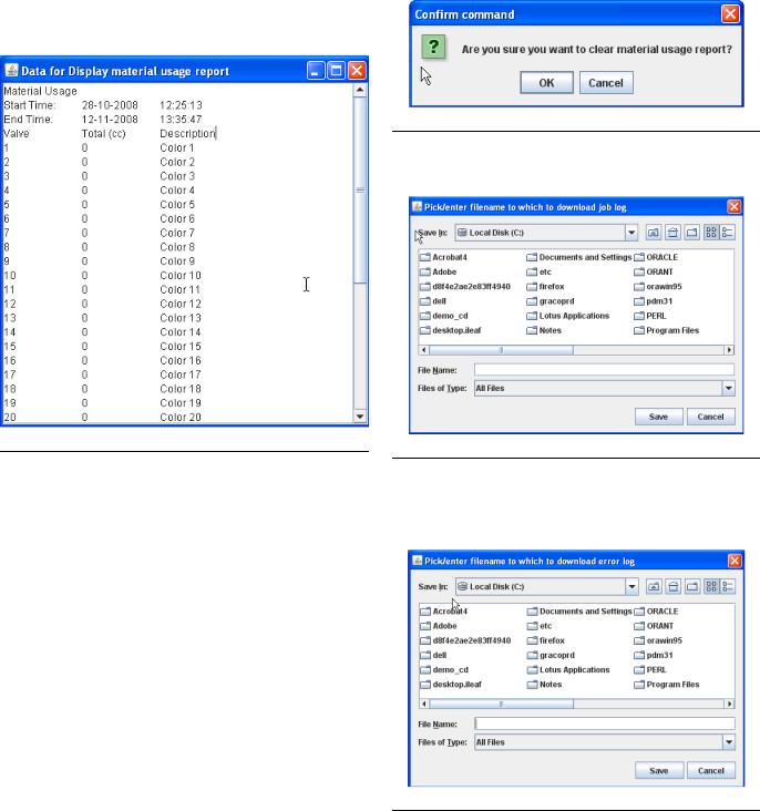
NOTE: Display material usage report - shows the material sprayed from the ProMix 2KS/3KS. See FIG. 15.
FIG. 15: Display Material Usage Report
Clear material usage report - deletes the material usage from the display.
FIG. 16: Clear Material Usage Report
Download job log - downloads the job log to the PC.
FIG. 17: Download Job Log
Download error log - downloads the error log to the PC.
FIG. 18: Download Error Log
10 |
313386D |
Display job log - displays the job number, date, time, recipe, ratio, target, volumes, grand totals, and any errors that occurred during the job. See FIG. 22.
Display error log - displays the number of alarms, date, time, recipe and what the error was. See FIG. 19.
FIG. 19: Display Error Log
FIG. 22: Display Job Log
ProMix 2KS/3KS Basic Web Interface (BWI)
Clear job log - deletes the jobs from the display. The screen will prompt for confirmation. See FIG. 20.
FIG. 20: Clear Job Log
Clear error log - deletes the errors from the display. The screen will prompt for confirmation. See FIG. 21.
FIG. 21: Clear Error Log
NOTE: For ProMix 3KS, a column will appear for Vol C.
Scroll to right to view Grand Totals and Errors
313386D |
11 |

Install the Advanced Web Interface (AWI) Module
Install the Advanced Web Interface (AWI) Module
Overview
The Graco Advanced Web Interface (AWI) Accessory allows communication between multiple ProMix 2KS/3KS and a PC over an Ethernet, enabling users to monitor the ProMix 2KS/3KS, view and change system setup parameters, and create reports.
NOTE: Screen views in this manual are shown using Microsoft Windows XP.
Location
The AWI module may be installed in a local ProMix network (see FIG. 25) or in a LAN network (see FIG. 26).
Do not install equipment approved only for non-hazard- ous location in a hazardous area.
Install the module near the EasyKey, in a non-hazard- ous area.
Mounting
1.See Dimensions, page 41.
2.Ensure that the wall and mounting hardware are strong enough to support the weight of the equipment, fluid, hoses, and stress caused during operation.
3.Using the equipment as a template, mark the mounting holes on the wall at a convenient height for the operator and so equipment is easily accessible for maintenance.
4.Drill mounting holes in the wall. Install anchors as needed.
5.Bolt equipment securely.
12 |
313386D |

Connect Module to EasyKey and PC
NOTICE
To avoid damaging circuit board when servicing, wear grounding strap on wrist and ground appropriately.
1.Shut off ProMix 2KS/3KS power (0 position). FIG. 23. Also shut off power at main circuit breaker.
 0 = OFF
TI12657a
FIG. 23: Power Off
Install the Advanced Web Interface (AWI) Module
2.Run a CAT5 cable from the EasyKey connector through the grommet and connect it to any port in the AWI module. Connect another CAT5 cable from the AWI module to the PC. See FIG. 24.
3.Plug in the module power cord.
NOTE: Multiple AWI server hubs can be connected to the AWI master module in series. See FIG. 25. Order Part No. 15V336 Hub, see page 39.
EasyKey (Bottom View) |
Advanced Web Interface Module |
Connect CAT5 Cables to any ports on module
TI12926a
TI12638a
CAT5 Cable Connector |
CAT5 Cable Grommets |
FIG. 24: EasyKey and Module Cable Connection Points
313386D |
13 |
Loading...