


Graco LineLazer II 3900, LineLazer II 5900, 232651, 232652, 233011 Instruction manual
...INSTRUCTIONS--REPAIR
KEEP FOR REFERENCE.
Read this and all related manuals for important warnings and instructions.
INSTRUCTIONS
308874
Rev. P
EN
First choice when quality counts.t
LineLazer II 3900 and 5900
3300 psi (230 bar, 23 MPa ) Maximum Working Pressure
LineLazer II 3900
Model |
Series |
Description |
|
|
|
232651 |
A |
Complete Sprayer |
|
|
|
232652 |
A |
Complete Sprayer with 2nd Gun Kit |
|
|
|
233011 |
A |
Complete Sprayer with Gauge and |
|
|
Pail Kit |
|
|
|
233012 |
A |
Complete Sprayer with 2nd Gun Kit, |
|
|
Gauge and Pail Kit |
|
|
|
LineLazer II 5900
Model |
Series |
Description |
|
|
|
232661 |
A |
Complete Sprayer |
|
|
|
232662 |
A |
Complete Sprayer with 2nd Gun Kit |
|
|
|
233013 |
A |
Complete Sprayer with Gauge and |
|
|
Pail Kit |
|
|
|
233014 |
A |
Complete Sprayer with 2nd Gun Kit, |
|
|
Gauge and Pail Kit |
|
|
|
Model 232651 |
8824A |
All models are not available in all countries
PATENTS PENDING
Related Manuals
Operation . . . . . . . . . . . . . . . . . . . . . . . . . . 308873 Displacement Pump . . . . . . . . . . . . . . . . . 308798 Spray Gun . . . . . . . . . . . . . . . . . . . . . . . . . 308235 Spray Tip . . . . . . . . . . . . . . . . . . . . . . . . . . . . . . . . . * PC Board . . . . . . . . . . . . . . . . . . . . . . . . . . 308919 Drain Valve Kit . . . . . . . . . . . . . . . . . . . . . . 308961 * for spray tip selection see page 4.
Table of Contents
Component Identification and Function . . . . . . . . . . . |
. 3 |
Pressure Control . . . . . . . . . . . . . . . . . . . . . . . . . . . . |
14 |
Spray Tip Selection Guide . . . . . . . . . . . . . . . . . . . . . . |
. 4 |
Displacement Pump . . . . . . . . . . . . . . . . . . . . . . . . . |
16 |
Maintenance . . . . . . . . . . . . . . . . . . . . . . . . . . . . . . . . . . |
. 5 |
Parts |
|
Troubleshooting . . . . . . . . . . . . . . . . . . . . . . . . . . . . . . . . |
6 |
Model 232651, 232661 LineLazer II . . . . . . . . . . . . |
17 |
Repair |
|
Pinion Assembly . . . . . . . . . . . . . . . . . . . . . . . . . . . . |
25 |
Bearing Housing & Connecting Rod . . . . . . . . . . . . . |
8 |
Complete Sprayers . . . . . . . . . . . . . . . . . . . . . . . . . . |
28 |
Drive Housing . . . . . . . . . . . . . . . . . . . . . . . . . . . . . . . . |
9 |
Pressure Control . . . . . . . . . . . . . . . . . . . . . . . . . . . . |
27 |
Pinion Assembly/Rotor/Field/Shaft/Clutch . . . . . . . |
10 |
Dimensions . . . . . . . . . . . . . . . . . . . . . . . . . . . . . . . . . . . |
29 |
Clamp . . . . . . . . . . . . . . . . . . . . . . . . . . . . . . . . . . . . . |
11 |
Technical Data . . . . . . . . . . . . . . . . . . . . . . . . . . . . . . . . |
29 |
Clutch Housing . . . . . . . . . . . . . . . . . . . . . . . . . . . . . . |
12 |
Graco Warranty . . . . . . . . . . . . . . . . . . . . . . . . . . . . . . . |
29 |
Engine . . . . . . . . . . . . . . . . . . . . . . . . . . . . . . . . . . . . . |
12 |
Graco Phone Number . . . . . . . . . . . . . . . . . . . . . . . . . . |
29 |

Warnings and Cautions
Warning Symbol
 WARNING
This symbol alerts you to the possibility of serious injury or death if you do not follow the instructions.
Caution Symbol
 CAUTION
This symbol alerts you to the possibility of damage to or destruction of equipment if you do not follow the instructions.
 WARNING
Fire and explosion can occur when spraying or flushing flammable fluid in an area where air circulation is poor and flammable vapors can be ignited by an open flame or sparks.
To help prevent a fire and explosion:
DUse outdoors or in an extremely well ventilated area.
DDo not use 1,1,1--trichloroethane, methylene chloride, other halogenated hydrocarbon solvents or fluids containing such solvents in pressurized aluminum equipment. Such use could
result in a chemical reaction, with the possibility of explosion.
DRemove, extinguish or unplug all ignition sources; tape wall switch. Do not smoke in spray area.
DNever fill fuel tank while the engine is running or hot. DGround Sprayer, object being sprayed, paint and solvent pails.
DHold gun firmly to side of a grounded pail when triggering into pail. DUse only conductive airless paint hose.
DNever run engine in inclosed area. DDo not flush with gasoline.
Fluid injection is a serious injury! If high pressure fluid pierces your skin, the injury might look like “just a cut”. But it is a serious wound! Get immediate surgical treatment.
To help prevent injection, always:
DEngage trigger safety latch when not spraying. DPoint gun away from yourself or anyone else.
DRelieve pressure before checking or repairing any leak.
DRelieve pressure when you turn off the sprayer or stop spraying.
DDo not use components rated less than system Maximum Working Pressure
DWhen flushing, ground equipment to grounded object with orange wire clamp.
DDo not flush equipment on asphalt or other non--conductive surfaces.
Never allow children to use this unit. If you are injured using this equipment, get immediate medical treatment.
2 308874

Component Identification and Function
Model 232651 |
J |
K |
|
||
ENGINE SPEED |
ENGINE STOP |
|
TIP SIZE |
|
|
|
|
V |
|
A |
|
B |
|
|
|
|
|
|
C |
H |
|
|
|
|
|
|
|
|
|
U |
F |
|
|
|
|
P |
|
|
|
|
|
|
|
|
|
|
|
L |
R |
G |
|
|
|
|
S |
|
|
M |
W |
N |
T |
|
Fig. 1 |
|
|
|
|
8825A |
|
|
|
|
|
|
A |
Pressure Control Switch |
ON/OFF, enables/disables clutch function |
|
||
B |
Pressure Adjusting Knob |
Controls fluid outlet pressure |
|
||
C |
Air Cleaner* |
|
|
Filters air entering the carburetor |
|
D |
Fuel Tank* |
|
|
Uses 86 octane gasoline |
|
E |
Muffler* |
|
|
Reduces noise of internal combustion |
|
F |
Spark Plug Cable* |
|
Routes electrical current to spark plug |
|
|
G |
Fuel Shutoff Lever* |
|
On/off lever to regulate fuel flow from gasoline tank to carburetor |
||
H |
Choke* |
|
|
Enriches air/gasoline mixture for cold starting |
|
J |
Throttle Lever* |
|
|
Adjusts engine speed for large or small orifice spray tips |
|
K |
Engine Switch* |
|
|
Enables/disables engine operation |
|
L |
Secondary Fluid Outlet |
Second hose and spray gun is connected here |
|
||
M |
Pressure Control |
|
Controls clutch cycling to maintain fluid pressure |
|
|
N |
Primary Fluid Outlet |
|
Hose and spray gun is connected here |
|
|
P |
Engine* |
|
|
4--cycle gasoline engine |
|
R |
Clutch Housing |
|
|
Transfers power from engine to drive assembly |
|
S |
Drive Housing |
|
|
Transfers power from clutch to displacement pump |
|
T |
Displacement Pump |
|
Provides fluid to be sprayed through spray gun |
|
|
U |
Fluid Filter |
|
|
Filters fluid between source and spray gun |
|
V |
Grounding Clamp and Wire |
Grounds sprayer system |
|
||
W |
Pressure Drain Valve |
|
Relieves fluid pressure when open |
|
|
* |
For more detailed explanations of these controls, refer to the Honda Engines Owner’s Manual; supplied |
||||
Install the spray tip in the gun. Sprayer is supplied with tip LLT319. For additional applications, use the Tip Selection Table on page 4.
308874 3
Spray Tip Selection Table
LineLazer Tip Selection Guide. Sprayer is supplied with tip LL5319. For additional applications, use the tip selection table as follows:
Note: the last three digits (LL5319) of the tip part number identifies the line width and tip orifice (opening) in millimeters. For example: the line width for tip LL5319 is 4 in. as shown in the table below. The tip orifice for tip LL5319 is 19 mm.
LineLazer Tip Selection Table |
|
|
||
|
|
|
|
|
Tip Size |
Line Width |
|
Used For |
|
|
|
|
||
286211* |
2 inches |
Sport court -- light film build |
||
|
|
|
||
LL5213* |
2 inches |
Sport court -- heavy film build |
||
|
|
|
||
LL5215* |
4 inches |
Alkyd paints only -- light film build |
||
|
|
|
||
LL5217 |
4 inches |
Alkyd paints only -- medium film build |
||
|
|
|
||
LL5219 |
4 inches |
Alkyd paints only -- heavy film build |
||
|
|
|
||
LL5315 |
4 inches |
Most traffic paints -- light film build |
||
|
|
|
||
LL5317 |
4 inches |
Most traffic paints -- medium film build |
||
|
|
|
||
LL5319 |
4 inches |
Most traffic paints -- medium film build |
||
|
|
|
||
LL5321 |
4 inches |
Most traffic paints -- heavy film build |
||
|
|
|
||
LL5323 |
4 inches |
Most traffic paints -- heavy film build |
||
|
|
|
|
|
LL5417# |
4 |
-- 8 inches |
All paints and high solids traffic paints -- light film build |
|
|
|
|
|
|
LL5419# |
4 |
-- 8 inches |
All paints and high solids |
traffic paints -- medium film build |
|
|
|
|
|
LL5421# |
4 |
-- 8 inches |
All paints and high solids |
traffic paints -- heavy film build |
|
|
|
|
|
LL5621 |
8 |
-- 12 inches |
All traffic paints -- light film build |
|
|
|
|
|
|
LL5623 |
8 |
-- 12 inches |
All traffic paints -- medium film build |
|
|
|
|
|
|
LL5625 |
8 |
-- 12 inches |
All traffic paints -- medium film build |
|
|
|
|
|
|
LL5627 |
8 |
-- 12 inches |
All traffic paints -- heavy film build |
|
* May require 100 mesh filter to minimize tip plugging.
# Best for cold weather applications.
How to Maximize Line Quality and Reduce Tip Wear. Observe the following suggestions to increase line quality and minimize sprayer tip wear.
1.Select a larger tip orifice and run the sprayer at a reduced operating pressure.
2.Running larger tip sizes (example: use tip LL5321 @ 2000 psi instead of LL5317 @ 3300 psi) will significantly increase tip life and reduce tip plugging. It will also produce a more uniform film build across the line.
4 308874

Maintenance
 WARNING
INJECTION HAZARD
The system pressure must be manually relieved to prevent the system from starting or spraying accidentally. Fluid
under high pressure can be injected through the skin and cause serious injury. To reduce the risk of an injury from injection, splashing fluid, or moving parts, follow the Pressure Relief Procedure whenever you:
D are instructed to relieve the pressure, D stop spraying,
D check or service any of the system equipment, D or install or clean the spray tip.
Pressure Relief Procedure
1.Lock gun trigger safety.
2.Turn engine ON/OFF switch to OFF.
3.Move pressure control switch to OFF and turn pressure control knob fully counterclockwise.
4.Unlock trigger safety. Hold metal part of gun firmly to side of grounded metal pail, and trigger gun to relieve pressure.
5.Lock gun trigger safety.
6.Open pressure drain valve. Leave valve open until ready to spray again.
7.Disconnect spark plug cable.
If you suspect that the spray tip or hose is completely clogged, or that pressure has not been fully relieved after following the steps above, VERY SLOWLY loosen tip guard retaining nut or hose end coupling to relieve pressure gradually, then loosen completely. Now clear tip or hose.
 CAUTION
For detailed engine maintenance and specifications, refer to separate Honda Engines Owner’s Manual, supplied.
DAILY: Check engine oil level and fill as necessary.
DAILY: Check hose for wear and damage.
DAILY: Check gun safety for proper operation.
DAILY: Check pressure drain valve for proper operation.
DAILY: Check and fill the gas tank.
AFTER THE FIRST 20 HOURS OF OPERATION:
Drain the oil and refill with clean oil.
WEEKLY: Remove air filter cover and clean element. Replace element, if necessary. If operating in an unusually dusty environment: check filter daily and replace, if necessary.
Replacement elements can be purchased from your local HONDA dealer.
WEEKLY: Check level of TSL in displacement pump packing nut. Fill nut, if necessary. Keep TSL in nut to help prevent fluid buildup on piston rod and premature wear of packings.
AFTER EACH 100 HOURS OF OPERATION:
Change oil.
MONTHLY: Oil connecting rod.
SPARK PLUG: Use only BPR6ES (NGK) or W20EPR--U (NIPPONDENSO) plug. Gap plug to 0.028 to 0.031 in. (0.7 to 0.8 mm). Use spark plug wrench when installing and removing plug.
Caster Wheel
(See letter call-outs in Parts drawing on page 21)
1.Once each year, tighten nut (A) until spring washer bottoms out. Then back off the nut 1/2 to 3/4 turn.
2.Once each year, tighten nut (B) until it begins to compress spring washer. Then tighten the nut an additional 1/4 turn.
3.Once each month, grease the wheel bearing (F).
4.Check pin (C) for wear. If pin is worn out, there will be play in the caster wheel. Reverse or replace the pin as needed.
5.Check caster wheel alignment as necessary. To align: loosen bolt (D), align wheel and tighten bolt (D).
308874 5

Troubleshooting
 WARNING
INJECTION HAZARD
To reduce risk of serious injury, including fluid injection or splashing in eyes or on skin, or injury from moving parts, always follow Pressure Relief Procedure Warning, page 5, before checking, adjusting, cleaning or shutting down sprayer. Disconnect spark plug!
Check everything in chart before disassembling sprayer.
PROBLEM |
CAUSE |
SOLUTION |
|
|
|
|
|
Engine won’t start |
Engine switch is OFF |
Turn engine switch ON |
|
|
|
|
|
|
Engine is out of gas |
Refill gas tank. Honda Engines Owner’s Manual. |
|
|
|
|
|
|
Engine oil level is low |
Try to start engine. Replenish oil, if necessary. |
|
|
|
Honda Engines Owner’s Manual. |
|
|
|
|
|
|
Spark plug cable is disconnected or damaged |
Connect spark plug cable or replace spark |
|
|
|
plug |
|
|
|
|
|
|
Cold engine |
Use choke |
|
|
|
|
|
|
Fuel shutoff lever is OFF |
Move lever to ON position |
|
|
|
|
|
|
Oil is seeping into combustion chamber |
Remove spark plug. Pull starter rope 3 or 4 |
|
|
|
times. Clean or replace spark plug. Try to start |
|
|
|
engine. Keep sprayer upright to avoid oil seep- |
|
|
|
age. |
|
|
|
|
|
Engine operates, but dis- |
Pressure control switch is OFF. |
Turn pressure control switch ON. |
|
placement pump does not |
|
|
|
Pressure setting is too low. |
Turn pressure adjusting knob clockwise to |
||
operate. |
|||
|
|
increase pressure. |
|
|
|
|
|
|
Fluid filter (318) is dirty. |
Clean filter. See page 27. |
|
|
|
|
|
|
Tip or tip filter is clogged. |
Clean tip or tip filter. See gun instruction |
|
|
|
manual. |
|
|
|
|
|
|
Displacement pump piston rod is stuck due to |
Repair pump. See manual 308798. |
|
|
dried paint. |
|
|
|
|
|
|
|
Connecting rod is worn or damaged. |
Replace connecting rod. See page 8. |
|
|
|
|
|
|
Drive housing is worn or damaged. |
Replace drive housing. See page 9. |
|
|
|
|
|
|
Electrical power is not energizing field. |
Check wiring connections. See page 12. |
|
|
|
Reference control board diagnostics. Page 15. |
|
|
|
With pressure control switch ON and pressure |
|
|
|
turned to MAXIMUM, use a test light to check |
|
|
|
for power between clutch terminals on control |
|
|
|
board. |
|
|
|
Remove black clutch wires from control board |
|
|
|
and measure resistance across wires. At 70_ |
|
|
|
F, the resistance must be between 1.2 ¦ 0.2 |
|
|
|
(LL 3900); 1.7 ¦ 0.2 (LL 5900); if not, replace |
|
|
|
pinion housing. |
|
|
|
Have pressure control checked by authorized |
|
|
|
Graco dealer. |
|
|
|
|
|
|
Clutch is worn, damaged, or incorrectly |
Replace clutch. See page 10. |
|
|
positioned. |
|
|
|
|
|
|
|
Pinion assembly is worn or damaged. |
Repair or replace pinion assembly, see pg 10. |
6 308874
PROBLEM |
CAUSE |
SOLUTION |
|
|
|
|
|
Pump output is low on |
Hose inlet screen (27) is clogged. |
Clean inlet screen. |
|
upstroke. |
|
|
|
Piston ball (25) is not seating. |
Service piston ball. See manual 308798. |
||
|
|||
|
|
|
|
|
Piston packings are worn or damaged. |
Replace packings. See manual 308798. |
|
|
|
|
|
|
O-ring (17) in displacement pump is worn or |
Replace o-ring. See manual 308798. |
|
|
damaged. |
|
|
|
|
|
|
Pump output is low on down- |
Hose strainer (27) is clogged. |
Clean strainer screen. |
|
stroke or on both strokes. |
|
|
|
Piston packings are worn or damaged. |
Replace packings. See manual 308798. |
||
|
|||
|
|
|
|
|
Intake valve ball is not seating properly. |
Clean intake valve. See manual 308798. |
|
|
|
|
|
|
Engine speed is too low. |
Increase throttle setting. See manual 308873. |
|
|
|
|
|
|
Clutch is worn or damaged. |
Replace clutch. See page 10. |
|
|
|
|
|
Paint leaks into wetcup. |
Wetcup is loose. |
Tighten wetcup just enough to stop leakage. |
|
|
|
|
|
|
Throat packings are worn or damaged. |
Replace packings. See manual 308798. |
|
|
|
|
|
|
Displacement rod is worn or damaged. |
Replace rod. See manual 308798. |
|
|
|
|
|
Fluid delivery is low. |
Inlet screen is clogged. |
Clean inlet screen. |
|
|
|
|
|
|
Pressure setting is too low. |
Increase pressure. See manual 308873. |
|
|
|
|
|
|
Engine speed is too low. |
Increase throttle setting. See manual 308873. |
|
|
|
|
|
|
Fluid filter (318), tip filter or tip is clogged or |
Clean filter. See manual 308873. Or, see gun |
|
|
dirty. |
instruction manual. |
|
|
|
|
|
|
Large pressure drop in hose with heavy |
Use larger diameter hose and/or reduce overall |
|
|
materials. |
length of hose. Use of more than 100 ft of 1/4 |
|
|
|
in. hose significantly reduces performance of |
|
|
|
sprayer. Use 3/8 in. hose for optimum perfor- |
|
|
|
mance (50 ft minimum). |
|
|
|
|
|
Fluid is spitting from gun. |
Air in pump or hose. |
Check and tighten all fluid connections. |
|
|
|
Reprime pump. See manual 308873. |
|
|
|
|
|
|
Tip is partially clogged. |
Clear tip. See gun instruction manual. |
|
|
|
|
|
|
Fluid supply is low or empty. |
Refill fluid supply. Prime pump. See manual |
|
|
|
308873. Check fluid supply often to prevent |
|
|
|
running pump dry. |
|
|
|
|
|
Pump is difficult to prime. |
Air in pump or hose. |
Check and tighten all fluid connections. |
|
|
|
Reduce engine speed and cycle pump as |
|
|
|
slowly as possible during priming. |
|
|
|
|
|
|
Intake valve is leaking. |
Clean intake valve. Be sure ball seat is not |
|
|
|
nicked or worn and that ball seats well. Reas- |
|
|
|
semble valve. |
|
|
|
|
|
|
Pump packings are worn. |
Replace pump packings. See manual 308798. |
|
|
|
|
|
|
Paint is too thick. |
Thin the paint according to the supplier’s |
|
|
|
recommendations. |
|
|
|
|
|
|
Engine speed is too high. |
Decrease throttle setting before priming pump. |
|
|
|
See manual 308873. |
|
|
|
|
|
Clutch squeaks each time |
Small irregularities of new clutch surfaces |
Clutch surfaces need to wear into each other. |
|
clutch engages. |
grind together and cause noise |
Noise will dissipate after a day of run time. |
|
|
|
|
|
High engine speed at no |
Misadjusted throttle setting. |
Reset throttle to 3600--3800 engine rpm at no |
|
load. |
|
load. |
|
|
|
|
|
|
Worn engine governor. |
Replace or service engine governor. |
|
|
|
|
308874 7
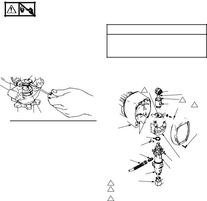
Bearing Housing and Connecting Rod
NOTE: The item numbers referenced are for the Hi-Boy models. The Lo-Boy models may have different item numbers. Use the Hi-Boy item number and part to find the corresponding Lo-Boy part and item number.
Removal |
|
1. |
Relieve pressure; page 5. |
|
2.Fig. 3. Remove screws (29) and front cover (86).
3.Unscrew suction tube (27) from pump, hold wrench on pump intake valve (A) to keep pump from loosening.
4.Disconnect pump outlet hose (25) from displacement pump outlet nipple (107).
5.Fig. 2. Use screwdriver to push up retaining spring (83) at top of pump. Push out pin (82).
82
Fig. 2 |
83 |
7675B |
6.Fig. 3. Loosen jam nut (81). Unscrew and remove displacement pump.
7.Remove four screws (31) and lockwashers (32) from bearing housing (84).
8.Pull connecting rod (85) and lightly tap lower rear of bearing housing (84) with plastic mallet to loosen from drive housing (87). Pull bearing housing and connecting rod assembly (85) off drive housing.
9.Inspect crank (B) for excessive wear and replace parts as needed.
Installation
10.Evenly lubricate inside of bronze bearing (C) in bearing housing (84), and inside of connecting rod link (D), with high-quality motor oil (do not use grease). Liberally pack roller bearing (E) in connecting rod assembly (85) with bearing grease.
11.Assemble connecting rod (85) and bearing housing (84).
12.Clean mating surfaces of bearing and drive housings.
13.Align connecting rod with crank (B) and carefully align locating pins (F) in drive housing (87) with holes in bearing housing (84). Push bearing housing onto drive housing or tap into place with plastic mallet.
 CAUTION
DO NOT use bearing housing screws (31) to align or seat bearing housing with drive housing. Align these parts with locating pins (F), to avoid premature bearing wear.
14.Install screws (31) and lockwashers (32) on bearing housing. Tighten evenly to 175 in-lb (19 N¡m).
15.Refer to Displacement Pump, Installation, page 16.
1 C |
E |
D |
|
|
|
|
|
|
85 |
2 |
|
|
31,32 |
3 |
|
|
|


 86 B
86 B


87
F 83 |
29 |
|
|
82 |
|
107 |
|
25 |
8184 |
|
|
A |
80 |
|
1 Oil |
27 |
|
2Pack with bearing grease 114819
3LL 3900: Torque to 200 in-lb (22.6 N¡m) LL 5900: Torque to 25 ft-lb (34 N¡m)
Fig. 3 |
Model 232651 shown |
8796A |
|
|
|
|
|
|
8 308874
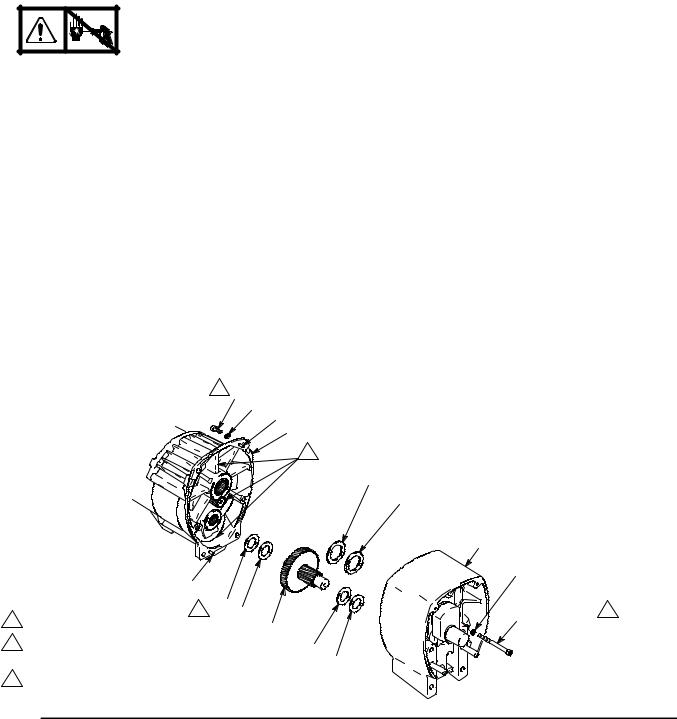
Drive Housing
Removal |
|
1. |
Relieve pressure; page 5. |
|
2.Fig. 4. Remove bearing housing. Do 1. through 8. of Bearing Housing and Connecting Rod procedure on page 8.
3.Remove two screws (51) and lockwashers (50).
4.Remove four screws (120) and lockwashers (119) from pinion housing (88a).
5.Lightly tap around drive housing (87c) to loosen drive housing. Pull drive housing straight off pinion housing. Be prepared to support gear cluster (78), which may also come out.
Installation
1.Liberally apply bearing grease (supplied with replacement gear cluster) to gear cluster (78). and to areas called out by note 3. Use full 0.62 pint (0.29 liter) of grease for LL 3900 and 0.68 pint (0.32 liter) of grease for LL 5900.
2.Place bronze colored washer (87g) on shaft protruding from large shaft of drive housing(87c). Note: If replacing a washer with pin holes with a washer without pin holes, remove guide pins from housing. Place silver colored washer (87h) on pins on pinion housing. Align gears and push new drive housing straight onto pinion housing and locating pins (B).
3.Install four screws (120) and lockwashers (119) into pinion housing (88a).
4.Install two screws (5) and lockwashers (50).
5.Fig. 3. Install bearing housing. Do 10. through 15. of Bearing Housing and Connecting Rod procedure on page 8.
2 |
120 |
|
119 B |
|
|
B |
1 |
LL 3900 only |
1 79 79 |
2 |
|
78 |
Torque to 125 in-lb -- LL 3900 |
||
|
Torque to 200 in-lb -- LL 5900 |
|
3 |
Apply remaining grease to these areas |
|
Fig. 4
88a
3
87h
87g
87c
50 (LL 3900)
51 (LL 5900)
51 (LL 3900)
52 (LL 5900) 2
77 79
TI0178A
308874 9
 Loading...