


Instructions – Parts List
WATERBASE COMPATIBLE
Ultra–litet Pistol Grip
Flo–Gun
308253N
EN
Model 235627, Series B
4000 psi (280 bar) Maximum Working Pressure
Tapered Valve Needle
Model 235628, Series D
6000 psi (415 bar) Maximum Working Pressure
Ball End Valve Needle, Abrasive Material Compatible
Model 243775, Series B
6000 psi (415 bar) Maximum Working Pressure
Tapered Valve Needle
Model 237607, Series A
4000 psi (280 bar) Maximum Working Pressure
Tapered Valve Needle, Abrasive Material Compatible
Model 237649, Series A
4000 psi (280 bar) Maximum Working Pressure
Tapered Valve Needle, Abrasive Material Compatible, Swivel Fitting Fluid Inlet
U.S. Patent No. Des. 342,654
Symbols . . . . . . . . . . . . . . . . . . . . . . . . . . . . . . . . . . . . . . 2
Warning . . . . . . . . . . . . . . . . . . . . . . . . . . . . . . . . . . . . . . . 2
Technical Data . . . . . . . . . . . . . . . . . . . . . . . . . . . . . . . . . 4
Installation . . . . . . . . . . . . . . . . . . . . . . . . . . . . . . . . . . . . . 5
Operation . . . . . . . . . . . . . . . . . . . . . . . . . . . . . . . . . . . . . 6 01609A
Service . . . . . . . . . . . . . . . . . . . . . . . . . . . . . . . . . . . . . . . 8
Parts . . . . . . . . . . . . . . . . . . . . . . . . . . . . . . . . . . . . . . . . 14
Graco Warranty and Limitation of Liability . . . . . . . . . 22
Graco Phone Number . . . . . . . . . . . . . . . . . . . . . . . . . . 22
Important Safety Instructions
Read all warnings and instructions in this manual.
Save these instructions.
Symbols
Warning Symbol
 WARNING
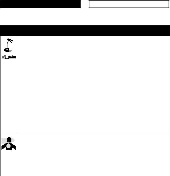
This symbol alerts you to the possibility of serious injury or death if you do not follow the instructions.
Caution Symbol
 CAUTION
This symbol alerts you to the possibility of damage to or destruction of equipment if you do not follow the instructions.
 WARNING
SKIN INJECTION HAZARD
Spray from the gun, hose leaks, or ruptured components can inject fluid into your body and cause extremely serious injury, including the need for amputation. Splashing fluid in the eyes or on the skin can also cause serious injury.
DFluid injected into the skin might look like just a cut, but it is a serious injury. Get immediate surgical treatment.
DDo not point the gun at anyone or at any part of the body.
DDo not put hand or fingers over the gun nozzle.
DDo not stop or deflect fluid leaks with your hand, body, glove, or rag.
DBe sure the gun trigger safety operates before dispensing.
DLock the gun trigger safety when you stop dispensing.
DIf the nozzle clogs while dispensing, fully release the trigger immediately
DFollow the Pressure Relief Procedure on page 6 whenever you: are instructed to relieve pressure; stop spraying; clean, check, or service the equipment; and install or clean the nozzle.
DTighten all the fluid connections before operating the equipment.
DCheck the hoses, tubes, and couplings daily. Replace worn, damaged, or loose parts immediately. Permanently coupled hoses cannot be repaired; replace the entire hose.
TOXIC FLUID HAZARD
Hazardous fluids or toxic fumes can cause a serious injury or death if splashed in the eyes or on the skin, swallowed, or inhaled.
DKnow the specific hazards of the fluid you are using. Read the fluid manufacturer’s warnings.
DStore hazardous fluid in an approved container. Dispose of the hazardous fluid according to all local, state, and national guidelines.
DWear appropriate protective clothing, gloves, eyewear, and respirator.
2 308253

 WARNING
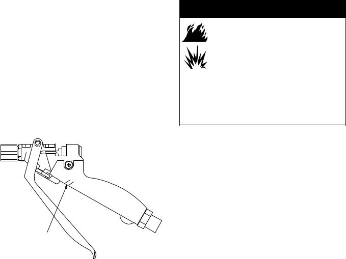
FIRE AND EXPLOSION HAZARD
Improper grounding, poor air ventilation, open flames, or sparks can cause a hazardous condition and result in a fire or explosion and serious injury.
DGround the equipment and the object being sprayed. See Ground the System on page 5.
DProvide fresh air ventilation to avoid the buildup of flammable fumes from solvent or the fluid being sprayed.
DExtinguish all the open flames or pilot lights in the spray area.
DElectrically disconnect all the equipment in the spray area.
DKeep the spray area free of debris, including solvent, rags, and gasoline.
DDo not turn on or off any light switch in the spray area while operating or if fumes are present.
DDo not smoke in the spray area.
DDo not operate a gasoline engine in the spray area.
DIf there is any static sparking while using the equipment, stop spraying immediately. Identify and correct the problem.
EQUIPMENT MISUSE HAZARD
Equipment misuse can cause the equipment to rupture, malfunction, or start unexpectedly and result
in a serious injury.
INSTRUCTIONS
DThis equipment is for professional use only.
DRead all the instruction manuals, tags, and labels before operating the equipment.
DUse the equipment only for its intended purpose. If you are uncertain about usage, call your Graco distributor.
DDo not alter or modify this equipment. Use only genuine Graco parts and accessories.
DCheck the equipment daily. Repair or replace worn or damaged parts immediately.
DDo not exceed the maximum working pressure of the lowest rated system component. See the front cover or the Technical Data for the maximum working pressure of your gun model.
DRoute the hoses away from the traffic areas, sharp edges, moving parts, and hot surfaces. Do not expose Graco hoses to temperatures above 180_F (82_C) or below –40_F (–40_C).
DDo not use the hoses to pull the equipment.
DUse only Graco approved hoses. Do not remove hose spring guards, which help protect the hose from rupture caused by kinks or bends near the couplings.
DUse fluids or solvents that are compatible with the equipment wetted parts. See the Technical Data section of all the equipment manuals. Read the fluid and solvent manufacturer’s warnings.
DDo not use 1,1, 1-trichloroethane, methylene chloride, other halogenated hydrocarbon solvents or fluids containing such solvents with gun Models 235627, 237607, and 237649. Such use could result in a serious chemical reaction with the gun’s aluminum parts, with the possibility of an explosion.
DComply with all applicable local, state and national fire, electrical and other safety regulations.
308253 3
Technical Data
Maximum Working Pressure
Models 235627, 237607,
and 237649 . . . . . . . . . . . . . 4000 psi (280 bar)
Models 235628 and 243775 . . . 6000 psi (415 bar)
Outlet Port Size
All Models . . . . . . . . . . 1/4 npt(f) with nut for metal flanged nozzle
Inlet Port Size
Models 235627 and 237607 . . . . . . . . . . . 1/4 npt(f) Models 235628 and 243775 . . . . . . . . . . . 1/2 npt(f) Model 237649 . . . . . . . . . 37_ SAE, 1/2-20 UNF(m)
Valve Orifice
Models 235627, 237607, 243775,
and 237649 . . . . . . . . . 0.20 in. (5.08 mm) dia. with tapered needle Model 235628 . . . . . . . 0.19 in. (4.83 mm) dia. with
0.25 in. (6.35 mm) carbide ball
Height
All Models . . . . . . . . . . . . . . . . 5.90 in. (149.86 mm)
Width
All Models . . . . . . . . . . . . . . . . . 1.20 in. (30.48 mm)
Length
Models 235627, 235628, 243775
and 237607 . . . . . . . . . . . 8.05 in. (204.47 mm)
Model 237649 . . . . . . . . . . . . . 8.90 in. (226.06 mm)
Weight
Model 235627 . . . . . . . . . . . . . . . . 15.45 oz. (439 g)
Model 235628 and 243775 . . . . . 22.70 oz. (636 g)
Model 237607 . . . . . . . . . . . . . . . . 15.45 oz. (439 g)
Model 237649 . . . . . . . . . . . . . . . . 17.00 oz. (483 g)
Wetted Parts
Model 235627
Fluid Section . . . . . . . . . . . . . . . . . . . Aluminum Fluid Tube . . . . . . . . 300 Series Stainless Steel Valve Needle . . . . . . . 17-4 PH Stainless Steel Valve Seat . . . . . . . . . 17-4 PH Stainless Steel Other . . . 316 Stainless Steel, fluoroelastomer,
and Polyurethane
Model 235628
Fluid Section . . . . . . . 17–4 PH Stainless Steel Fluid Tube . . . . . . . . 300 Series Stainless Steel Valve Needle . . . . . . . . . Carbide and 17–4 PH Stainless Steel Valve Seat . . . . . . . . . . . Carbide and 17–4 PH Stainless Steel
Other . Stainless Steel, fluoroelastomer, PTFE ;CV75,
and Polyurethane
Model 243775
Fluid Section . . . . . . . 17–4 PH Stainless Steel Fluid Tube . . . . . . . . 300 Series Stainless Steel Valve Needle . . . . . . . . . Carbide and 17–4 PH Stainless Steel Valve Seat . . . . . . . . . . . Carbide and 17–4 PH Stainless Steel
Other Stainless Steel, fluoroelastomer, PTFE, and Polyurethane
Model 237607
Fluid Section . . . . . . . . . . . . . . . . . . . Aluminum Fluid Tube . . . . . . . . 300 Series Stainless Steel Valve Needle . . . . . . . . . Carbide and 17-4 PH Stainless Steel Valve Seat . . . . . . . . . . . Carbide and 17-4 PH Stainless Steel
Other . . . 316 Stainless Steel, fluoroelastomer, and Polyurethane
Model 237649
Fluid Section . . . . . . . . . . . . . . . . . . . Aluminum Fluid Tube . . . . . . . . 300 Series Stainless Steel Valve Needle . . . . . . . . . Carbide and 17-4 PH Stainless Steel Valve Seat . . . . . . . . . . . Carbide and 17-4 PH
300 Series Stainless Steel Swivel Inlet Fitting . . . 303 Stainless Steel, and Ultra High Molecular Weight Polyethylene Other . . . 316 Stainless Steel, fluoroelastomer, and Polyurethane
4 308253

Installation
Ground the System
 WARNING
FIRE AND EXPLOSION HAZARD
To reduce the risk of a fire, explosion, and serious injury, proper electrical grounding of every part of your system is essential. Read the warning section,
FIRE AND EXPLOSION HAZARD, on page 3 and follow the grounding instructions below.
The following grounding instructions are minimum requirements for a basic dispensing system. Your system may include other equipment or objects which must be grounded. Check your local electrical code for detailed grounding instructions for your area and type of equipment. Your system must be connected to a true earth ground.
1.Pump: ground the pump by connecting a ground wire and clamp as described in your separate pump instruction manual.
2.Air compressors and hydraulic power supplies: ground the equipment according to the manufacturer’s recommendations.
3.Fluid hoses: use only grounded fluid hoses with a maximum of 500 feet (150 m) combined hose length to ensure grounding continuity. Check the electrical resistance of your fluid hoses at least once a week. If your hose does not have a tag on it which specifies the maximum electrical resistance, contact the hose supplier or manufacturer for the maximum resistance limits. If the hose resistance exceeds the recommended limits, replace it immediately.
4.Flo-gun: ground the gun by connecting it to a properly grounded fluid hose and pump.
5.Fluid supply container: ground according to the local code.
6.Flammable liquids in the spray area: must be kept in approved, grounded containers. Do not store more than the quantity needed for one shift.
7.All solvent pails used when flushing: ground according to local code. Use only metal pails, which are conductive. Do not place the pail on a non-conductive surface, such as paper or cardboard, which interrupts the grounding continuity.
8.To maintain grounding continuity when flushing or relieving pressure: hold a metal part of the gun firmly to the side of a grounded metal pail, then trigger the gun.
308253 5

Operation
Pressure Relief Procedure
 WARNING
SKIN INJECTION HAZARD
The system pressure must be manually relieved to prevent the system from
starting or spraying accidentally. Fluid under high pressure can be injected through the skin and cause a serious injury. To reduce the risk of an injury from injection, splashing fluid, or moving parts, follow the Pressure Relief Procedure whenever you:
Dare instructed to relieve the pressure,
Dstop dispensing,
Dcheck or service any of the system equipment,
Dor install or clean the nozzle.
1.Fully release the gun trigger and lock the gun trigger safety by rotating the safety forward. See Fig. 1.
2.Shut off the fluid supply pump.
3.Hold a metal part of the gun firmly to the side of a grounded metal waste container. Unlock the gun trigger safety by rotating the safety backward. See Fig. 2. Trigger the gun to relieve fluid pressure.
4.Fully release the gun trigger and lock the gun trigger safety by rotating the safety forward.
5.Open the pump drain valve to help relieve fluid pressure in the pump, hose, and gun. Triggering the gun to relieve pressure may not be sufficient. Have a container ready to catch the drainage.
6.Leave the drain valve open until you are ready to dispense again.
7.If you think that the gun nozzle or fluid hose is completely clogged or that pressure has not been fully relieved after following the steps above, very slowly loosen the hose end coupling and relieve pressure gradually, then loosen the coupling completely. Clear the nozzle or hose obstruction.
Gun Trigger Safety
 WARNING
SKIN INJECTION HAZARD
To prevent accidental triggering of the gun and reduce the risk of a serious
injury, including fluid injection or splashing in the eyes or on skin, lock the gun trigger safety when you stop dispensing.
To lock the gun safety, release the trigger and rotate the safety toward the trigger as shown in Fig. 1.
NOTE: Do not try to force the trigger valve open with the safety engaged. This could result in component failure.
Locked
Fig. 1 |
01610A |
|
|
|
|
To unlock the trigger safety, rotate the safety toward the handle as shown in Fig. 2.
Unlocked
Fig. 2 |
01610A |
|
|
|
|
6 308253
Operation
Dispensing
1.Start the fluid supply pump.
2.The fluid flow rate is controlled at the pump. Adjust the pump pressure to obtain the desired flow rate. It is recommended that you use the lowest pressure necessary to dispense the fluid. The pressure adjustment will depend on the hose length, the viscosity of the fluid, and the gun nozzle size.
3.Unlock the gun trigger safety.
4.Squeeze the trigger in all the way. Fluid flow begins with the slightest pressure on the trigger and stops when the trigger is released.
NOTE: Periodically inspect the vent in the gun handle for fluid buildup which could indicate an internal leak. See Fig. 3. Service the fluid tube and o-ring as needed.
Flushing Safety
 WARNING
FIRE AND EXPLOSION HAZARD
To reduce the risk of a fire, explosion, or serious injury,
DBe sure the entire system and flushing pails are properly grounded before flushing the gun or system.
Read Grounding the System, on page 5.
DUse the lowest possible fluid pressure and maintain firm metal-to-metal contact between the gun and the grounded metal pail during flushing.
Vent
Fig. 3 |
01807A |
|
|
|
|
308253 7
 Loading...