Graco 237579, 237746, 237578 User Manual

Instructions-Parts List
Elevators and |
|
Pump Supports |
EN |
|
306287W |
|
|
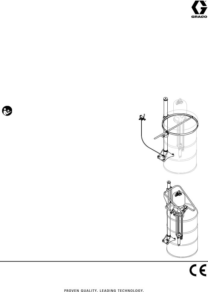
Used to raise and lower select Graco circulation and supply pumps. For professional use only.
200 psi (1.4 MPa, 14 bar) Maximum Air Input Pressure
Important Safety Instructions
Read all warnings and instructions in this manual. Save these instructions.
See page 2 for a list of models.
06529b
06523b
Table of Contents
Table of Contents
Table of Contents . . . . . . . . . . . . . . . . . . . . . . . . . . 2
List of Models . . . . . . . . . . . . . . . . . . . . . . . . . . . . . 2
Warnings . . . . . . . . . . . . . . . . . . . . . . . . . . . . . . . . . 3
Installation . . . . . . . . . . . . . . . . . . . . . . . . . . . . . . . . 4
General Information . . . . . . . . . . . . . . . . . . . . . . 4
Fixed Mount Elevator . . . . . . . . . . . . . . . . . . . . . 4
Pump Support Bracket . . . . . . . . . . . . . . . . . . . . 5
Cover Support . . . . . . . . . . . . . . . . . . . . . . . . . . . 5
Air Connection . . . . . . . . . . . . . . . . . . . . . . . . . . 5
Operation . . . . . . . . . . . . . . . . . . . . . . . . . . . . . . . . . |
6 |
Starting and Adjusting the Elevator . . . . . . . . . . |
6 |
Changing Drums . . . . . . . . . . . . . . . . . . . . . . . . . |
6 |
Service . . . . . . . . . . . . . . . . . . . . . . . . . . . . . . . . . . . 7
Lubrication . . . . . . . . . . . . . . . . . . . . . . . . . . . . . 7 Seals and Gaskets . . . . . . . . . . . . . . . . . . . . . . . 7 Push-Pull Valve . . . . . . . . . . . . . . . . . . . . . . . . . 7
Parts . . . . . . . . . . . . . . . . . . . . . . . . . . . . . . . . . . . . . 8
Elevator . . . . . . . . . . . . . . . . . . . . . . . . . . . . . . . . 8 Support and Control . . . . . . . . . . . . . . . . . . . . . 10 Support and Control
(Models 237746 Series A, 241663 Series A, 237579, 237578) . . . . . . . . . . . . . . . . . . . . . 12
Notes . . . . . . . . . . . . . . . . . . . . . . . . . . . . . . . . . . . . 14 Dimensions . . . . . . . . . . . . . . . . . . . . . . . . . . . . . . . 15 Graco Standard Warranty . . . . . . . . . . . . . . . . . . . 16
List of Models
Elevators
Part Number |
Series |
Description |
|
|
|
204385 |
D |
Standard Elevator with Fixed Mounting |
|
|
|
207408 |
C |
Heavy Duty Elevator with Fixed Mounting - Designed with increased |
|
|
strength and rigidity to allow frequent raising and lowering loads ranging |
|
|
between 120-400 lbs. (54-81 kg). |
|
|
|
205332 |
B |
Bare Elevator |
|
|
|
237746 |
A |
Elevator Assembly, includes 204385 Elevator, 237578 Cover Support, |
|
|
and 237579 Air Control Kit |
|
|
|
241663 |
A |
Elevator Assembly, includes 204385 Elevator, 207562 Cover Support, |
|
|
and 207561 Air Control Kit |
|
|
|
Pump Supports
Part Number |
Series |
Description |
|
|
|
206232 |
A |
Frame Support (open mounting) |
|
|
|
207562 |
A |
Ring Support (cover mounting) |
|
|
|
237578 |
A |
Ring Support (cover mounting) |
|
|
|
Air Control Kits
Part Number |
Series |
Description |
|
|
|
207561 |
A |
For use with Supports 206232 or 207562 |
|
|
|
237579 |
A |
For use with Support 237578 |
|
|
|
2 |
306287W |

Warnings
Warnings
The following warnings are for the setup, use, grounding, maintenance, and repair of this equipment. The exclamation point symbol alerts you to a general warning and the hazard symbols refer to procedure-specific risks. When these symbols appear in the body of this manual or on warning labels, refer back to these Warnings. Product-specific hazard symbols and warnings not covered in this section may appear throughout the body of this manual where applicable.
WARNING
EQUIPMENT MISUSE HAZARD
Misuse can cause death or serious injury.
•Do not operate the unit when fatigued or under the influence of drugs or alcohol.
•Do not exceed the maximum working pressure or temperature rating of the lowest rated system component. See Technical Data in all equipment manuals.
•Use fluids and solvents that are compatible with equipment wetted parts. See Technical Data in all equipment manuals. Read fluid and solvent manufacturer’s warnings. For complete information about your material, request MSDS from distributor or retailer.
•Do not leave the work area while equipment is energized or under pressure.
•Turn off all equipment and follow the Pressure Relief Procedure when equipment is not in use.
•Check equipment daily. Repair or replace worn or damaged parts immediately with genuine manufacturer’s replacement parts only.
•Do not alter or modify equipment. Alterations or modifications may void agency approvals and create safety hazards.
•Make sure all equipment is rated and approved for the environment in which you are using it.
•Use equipment only for its intended purpose. Call your distributor for information.
•Route hoses and cables away from traffic areas, sharp edges, moving parts, and hot surfaces.
•Do not kink or over bend hoses or use hoses to pull equipment.
•Keep children and animals away from work area.
•Comply with all applicable safety regulations.
MOVING PARTS HAZARD
Moving parts can pinch, cut or amputate fingers and other body parts.
•Keep clear of moving parts.
•Do not operate equipment with protective guards or covers removed.
•Pressurized equipment can start without warning. Before checking, moving, or servicing equipment, follow the Pressure Relief Procedure in your separate pump manual and disconnect all power sources.
306287W |
3 |

Installation
Installation
General Information
NOTE: Reference numbers and letters in parentheses in the text refer to the callouts in the figures and the parts drawing.
NOTE: Always use Genuine Graco Parts and Accessories, available from your Graco distributor. If you supply your own accessories, be sure they are adequately sized and pressure rated for your system.
To reduce the risk of serious injury, including fluid injection, splashing in the eyes or on the skin, or injury from moving parts:
1.Always relieve air and fluid pressure in the pump before raising the elevator.
2.Keep your fingers and hands away from moving parts when raising or lowering the elevator to prevent pinching or amputating them including between the drum and pump mounting assembly.
3.When the pump is in the raised elevator position, do not leave it unattended. Keep air supplied to the elevator. Block the pump, drum cover or pump support bracket before working on the pump.
4.Before working on the elevator, remove the pump and relieve air pressure to the elevator.
Fixed Mount Elevator
Locate the elevator where there is at least 9 ft (2.75 m) overhead clearance. Mark and drill holes for 0.5 in. (13 mm) mounting bolts. See FIG. 2 and the dimensional drawing on page 15. Level the base (17), using shims if necessary. Secure the base to the floor using four 1/2 in. (13 mm) mounting bolts which are long enough to prevent the elevator from tipping.
40
14 or 28 
17
06523b
FIG. 1
0.25 in (6.4 mm)


 Level
Level
Raised: 94 in (2390 mm)
Shim
0.5 in (13mm) bolt
Lowered: 55 in (1400 mm) 


06530
FIG. 2
4 |
306287W |

Installation
Pump Support Bracket
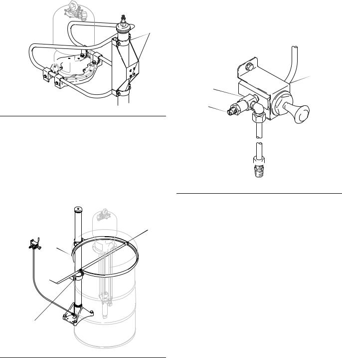
Set an open drum against the elevator base (17). Position the bracket (40) on top of the drum so that the clamp (34) recesses are tight against the elevator riser tube (14 or 28). See FIG. 1 and FIG. 3. Raise the riser tube up about 0.25 in. (6.4 mm), install the clamps (34) and tighten securely. Attach the pump mounting brackets (38)
Pump Support
Ref. No. 31
34
40 
38 


06528
FIG. 3
Cover Support
Place the cover in its proper position in the support ring (49) and tighten the capscrews (45). Set an open drum against the elevator base (17) and put the cover on the drum so the support clamp (44) recesses are tight against the elevator riser tube (14 or 28). Raise the tube 0.25 in. (6.4 mm), then tighten the clamp screws (42). See FIG. 4.
14 or 28
49, 45
49
45
48
44, 42
17
06529b
FIG. 4
Air Connection
Screw the restrictor valve (55) into the push-pull valve (60) as shown in FIG. 5. Mount the valve on the wall at a convenient height, using the mounting bracket (54). Connect the master air supply to the valve. Screw the elbow fitting (52) into the 1/8 npt(f) inlet of the restrictor valve. Push one end of the copper tube (51) into the elbow and tighten the fitting. Screw the straight fitting (53) into the base (17) of the elevator. Push the other end of the copper tube (51) into this fitting and tighten the fitting.
Push-Pull Valve
Ref. No. 60
54
60
55
52 
51

06531
FIG. 5
306287W |
5 |
 Loading...