


 Loading...
Repair - Parts
E-Flo® 4-Ball
Piston Pumps
311594Z
EN
Durable, energy efficient piston pumps for high volume paint circulation applications. For professional use only.
Important Safety Instructions
Read all warnings and instructions in this manual.
Save these instructions.
See page 3 for model information, including maximum working pressure. See page 5 for approvals.
E-Flo 4000 Pump Shown
ti8317c
Related Manuals
Contents
Related Manuals . . . . . . . . . . . . . . . . . . . . . . . . . . . 2
Models . . . . . . . . . . . . . . . . . . . . . . . . . . . . . . . . . . . 3
E-Flo 4-Ball Piston Pumps . . . . . . . . . . . . . . . . . 3
Maximum Working Pressure and Pump Operational
Limits . . . . . . . . . . . . . . . . . . . . . . . . . . . . . . 3
Approvals . . . . . . . . . . . . . . . . . . . . . . . . . . . . . . . . . 5
Warnings . . . . . . . . . . . . . . . . . . . . . . . . . . . . . . . . . 6
Pressure Relief Procedure . . . . . . . . . . . . . . . . . . . 9
Flushing . . . . . . . . . . . . . . . . . . . . . . . . . . . . . . . . . . 9
Troubleshooting . . . . . . . . . . . . . . . . . . . . . . . . . . 10
Electrical Diagrams . . . . . . . . . . . . . . . . . . . . . . . . 12
Repair . . . . . . . . . . . . . . . . . . . . . . . . . . . . . . . . . . . 15
Fluid Section . . . . . . . . . . . . . . . . . . . . . . . . . . . 15
Disassembly . . . . . . . . . . . . . . . . . . . . . . . . 15
Reassembly . . . . . . . . . . . . . . . . . . . . . . . . 17
Slider Cylinder Rebuild Kit 15H874 . . . . . . 18
Slider Cylinder Collector Kit 247341 . . . . . . 19
Electrical Section . . . . . . . . . . . . . . . . . . . . . . . 20
Pressure Transducer Kit 15H876 . . . . . . . . 20
Pressure Sensor Calibration Information
(non-ACS systems) . . . . . . . . . . . . . . . 22
Pressure Transducer Calibration Procedure (non-ACS systems) . . . . . . . . . . . . . . . 22
TDC Sensor Kit 15H877 . . . . . . . . . . . . . . . 23 Position Sensor . . . . . . . . . . . . . . . . . . . . . . 24 Drive Section . . . . . . . . . . . . . . . . . . . . . . . . . . . 26 Slider Bearing Kit 15H882 . . . . . . . . . . . . . . 26 Drive Linkage Rebuild Kit 15H873 . . . . . . . 28 Crank Arm Kit 15H883 . . . . . . . . . . . . . . . . 29 Motor/Gear Reducer . . . . . . . . . . . . . . . . . . . . . 30 Motor Removal . . . . . . . . . . . . . . . . . . . . . . 30 Motor/Coupler is Difficult to Remove . . . . . 31 Motor Installation . . . . . . . . . . . . . . . . . . . . . 33 Gear Reducer Seal Kit 15H871 . . . . . . . . . 34 Gear Reducer Replacement Kit . . . . . . . . . 36
Parts . . . . . . . . . . . . . . . . . . . . . . . . . . . . . . . . . . . . 42
Drive Section . . . . . . . . . . . . . . . . . . . . . . . . . . . 42 Fluid Section . . . . . . . . . . . . . . . . . . . . . . . . . . . 43 Common Parts . . . . . . . . . . . . . . . . . . . . . . . . . . 44 Model-Specific Parts . . . . . . . . . . . . . . . . . . . . . 46 Gear Reducer . . . . . . . . . . . . . . . . . . . . . . . . . . 49
Technical Data . . . . . . . . . . . . . . . . . . . . . . . . . . . . 50 Graco Standard Warranty . . . . . . . . . . . . . . . . . . . 52 Graco Information . . . . . . . . . . . . . . . . . . . . . . . . . 52
Related Manuals
Manual Description
311592 E-Flo Installation Manual
311593 E-Flo Operation Manual
311595 Pneumatic Back Pressure Regulator
311596 Variable Frequency Drive Instructions
311603 Sensor Circuit Option
3A0539 4-Ball Lowers
2 |
311594Z |
Models
Models
E-Flo 4-Ball Piston Pumps
Check your pump’s identification plate (ID) for the 6-digit part number of your |
|
|
pump. Use the following matrix to define the construction of your pump, based |
|
|
on the six digits. For example, Pump Part No. E P 2 1 6 0 represents electric |
|
|
power (E), pump (P), 230/460V motor (2), sensor circuit installed (1), 2000 cc |
ID |
|
MaxLife lower (6), and no stand installed (0). To order replacement parts, see |
||
|
||
Parts, beginning on page 42. |
ti8912a |
E |
P |
|
2 |
|
1 |
|
6 |
|
0 |
||
|
|
|
|
|
|
|
|
|
|
|
|
First Digit |
Second Digit |
|
Third Digit |
|
|
Fourth Digit |
|
Fifth Digit |
|
Sixth Digit |
|
|
|
|
|
|
|
|
|
|
|
|
|
Power |
Equipment |
|
|
|
|
|
|
|
|
|
|
Source |
Style |
|
Motor |
|
Sensor Circuit |
|
Lower Size |
Stand Option |
|||
|
|
|
|
|
|
|
|
|
|
|
|
E (electric) |
P (pump) |
0 |
No motor |
0 |
|
No circuit |
1 |
1000 cc Chrome |
0 |
|
No stand |
|
|
|
|
|
|
installed |
|
|
|
|
installed |
|
|
|
|
|
|
|
|
|
|
|
|
|
|
1 |
230/400V, 5HP, |
1 |
|
Circuit installed |
2 |
1500 cc Chrome |
1 |
|
Stand |
|
|
|
ATEX |
|
|
|
|
|
|
|
installed |
|
|
2 |
230/460V, 5HP, |
|
|
|
3 |
2000 cc Chrome |
|
|
|
|
|
|
UL/CSA |
|
|
|
|
|
|
|
|
|
|
3 |
230/400V, 3HP, |
|
|
|
4 |
1000 cc MaxLife® |
|
|
|
|
|
|
ATEX |
|
|
|
|
|
|
|
|
|
|
4 |
230/460V, 3HP, |
|
|
|
5 |
1500 cc MaxLife |
|
|
|
|
|
|
UL/CSA |
|
|
|
|
|
|
|
|
|
|
|
|
|
|
|
6 |
2000 cc MaxLife |
|
|
|
|
|
|
|
|
|
|
7 |
750 cc Chrome |
|
|
|
|
|
|
|
|
|
|
8 |
750 cc MaxLife |
|
|
|
|
|
|
|
|
|
|
|
|
|
|
|
Maximum Working Pressure and Pump Operational Limits
E-Flo 1500: 425 psi (2.93 MPa, 29.3 bar) Maximum Working Pressure
E-Flo 2000: 460 psi (3.22 MPa, 32.2 bar) Maximum Working Pressure
E-Flo 3000: 330 psi (2.31 MPa, 23.1 bar) Maximum Working Pressure
E-Flo 4000: 250 psi (1.75 MPa, 17.5 bar) Maximum Working Pressure
See Technical Data, page 50, for pressure and flow limits.
311594Z |
3 |

Models
4 |
311594Z |
Approvals
Approvals
The E-Flo Pump meets requirements of the following approval agencies.
Refer to the individual components for other specific hazardous location listings.
Component |
Part No. |
Approvals |
|
|
|
Mechanical Pump |
|
|
|
|
c T3 |
|
|
|
|
ATEX |
|
|
EP1XXX |
|
|
EP3XXX |
|
Motor |
|
Ex de IIC T4 - CESI 05 ATEX 110X |
|
|
|
UL/CSA |
|
|
|
|
|
|
EP2XXX |
Class I, Group D, Class II, Group F and G, Division 1, T3B |
|
Hazardous Locations |
|
|
EP4XXX |
|
|
|
Class 1, Div. 1, Group C & D T3 Hazardous Locations
IS Sensor Circuit |
EPX1XX |
EEx ib IIB Ta = 0°C - 50°C - FM 06 ATEX 0025U
Ex ib IIB Ta = 0°C - 50°C - KTL 13-KB4BO-0088
311594Z |
5 |
Warnings
Warnings
The following warnings are for the setup, use, grounding, maintenance, and repair of this equipment. The exclamation point symbol alerts you to a general warning and the hazard symbols refer to procedure-specific risks. When these symbols appear in the body of this manual, refer back to these Warnings. Product-specific hazard symbols and warnings not covered in this section may appear throughout the body of this manual where applicable.
 WARNING
FIRE AND EXPLOSION HAZARD
Flammable fumes, such as solvent and paint fumes, in work area can ignite or explode. To help prevent fire and explosion:
• Use equipment only in well ventilated area.
• Eliminate all ignition sources; such as pilot lights, cigarettes, portable electric lamps, and plastic drop cloths (potential static arc).
• Keep work area free of debris, including solvent, rags and gasoline.
•Do not plug or unplug power cords, or turn power or light switches on or off when flammable fumes are present.
•Ground all equipment in the work area. See Grounding instructions.
•Use only grounded hoses.
•Hold gun firmly to side of grounded pail when triggering into pail.
•If there is static sparking or you feel a shock, stop operation immediately. Do not use equipment until you identify and correct the problem.
•Keep a working fire extinguisher in the work area.
Static charge may build up on plastic parts during cleaning and could discharge and ignite flammable vapors. To help prevent fire and explosion:
•Clean plastic parts only in a well ventilated area.
•Do not clean with a dry cloth.
•Do not operate electrostatic guns in equipment work area.
•
EQUIPMENT MISUSE HAZARD
Misuse can cause death or serious injury.
•Do not operate the unit when fatigued or under the influence of drugs or alcohol.
•Do not exceed the maximum working pressure or temperature rating of the lowest rated system component. See Technical Data in all equipment manuals.
•Use fluids and solvents that are compatible with equipment wetted parts. See Technical Data in all equipment manuals. Read fluid and solvent manufacturer’s warnings. For complete information about your material, request MSDS forms from distributor or retailer.
•Check equipment daily. Repair or replace worn or damaged parts immediately with genuine manufacturer’s replacement parts only.
•Do not alter or modify equipment.
•Use equipment only for its intended purpose. Call your distributor for information.
•Route hoses and cables away from traffic areas, sharp edges, moving parts, and hot surfaces.
•Do not kink or over bend hoses or use hoses to pull equipment.
•Keep children and animals away from work area.
•Comply with all applicable safety regulations.
6 |
311594Z |
Warnings
 WARNING
ELECTRIC SHOCK HAZARD
Improper grounding, setup, or usage of the system can cause electric shock.
•Turn off and disconnect power at main switch before disconnecting any cables and before servicing equipment.
•Connect only to grounded power source.
•All electrical wiring must be done by a qualified electrician and comply with all local codes and regulations.
PRESSURIZED EQUIPMENT HAZARD
Fluid from the gun/dispense valve, leaks, or ruptured components can splash in the eyes or on skin and cause serious injury.
•Follow Pressure Relief Procedure in this manual, when you stop spraying and before cleaning, checking, or servicing equipment.
•Tighten all fluid connections before operating the equipment.
•Check hoses, tubes, and couplings daily. Replace worn or damaged parts immediately.
MOVING PARTS HAZARD
Moving parts can pinch or amputate fingers and other body parts.
•Keep clear of moving parts.
•Do not operate equipment with protective guards or covers removed.
•Pressurized equipment can start without warning. Before checking, moving, or servicing equipment, follow the Pressure Relief Procedure in this manual. Disconnect power or air supply.
TOXIC FLUID OR FUMES HAZARD
Toxic fluids or fumes can cause serious injury or death if splashed in the eyes or on skin, inhaled, or swallowed.
•Read MSDS’s to know the specific hazards of the fluids you are using.
•Store hazardous fluid in approved containers, and dispose of it according to applicable guidelines.
•Always wear impervious gloves when spraying or cleaning equipment.
PERSONAL PROTECTIVE EQUIPMENT
You must wear appropriate protective equipment when operating, servicing, or when in the operating area of the equipment to help protect you from serious injury, including eye injury, inhalation of toxic fumes, burns, and hearing loss. This equipment includes but is not limited to:
•Protective eyewear
•Clothing and respirator as recommended by the fluid and solvent manufacturer
•Gloves
•Hearing protection
BURN HAZARD
Equipment surfaces and fluid that’s heated can become very hot during operation. To avoid severe burns, do not touch hot fluid or equipment. Wait until equipment/fluid has cooled completely.
311594Z |
7 |

Warnings
8 |
311594Z |
Pressure Relief Procedure
Pressure Relief |
Flushing |
||||||
Procedure |
|
|
|
|
|
|
|
|
|
|
|
|
|
|
|
|
|
|
|
|
|
|
|
System pressure can cause the pump to cycle unexpectedly, which could result in serious injury from splashing or moving parts.
1.Set START/STOP switch (ST) to STOP.
2.Push in SECURE DISABLE (SD) switch.
3.Open the back pressure regulator and all fluid drain valves in the system, having a waste container ready to catch drainage. Leave open until you are ready to pressurize system again.
4.Check that pressure gauges on fluid supply and return lines read zero. If gauges do not read zero, determine cause and carefully relieve pressure by VERY SLOWLY loosening a fitting. Clear obstruction before pressurizing system again.
•Flush before changing colors, before storing, and before repairing equipment.
•Flush at the lowest pressure possible. Check connectors for leaks and tighten as necessary.
•Flush with a fluid that is compatible with the fluid being dispensed and the equipment wetted parts.
1.Follow Pressure Relief Procedure, page 9.
2.Supply the appropriate flushing material to the system.
3.Set pump to lowest possible fluid pressure, and start the pump.
4.Flush long enough to thoroughly clean the system.
5.Follow Pressure Relief Procedure, page 9.
311594Z |
9 |

Troubleshooting
Troubleshooting
|
|
|
|
|
|
|
|
|
1. Relieve the pressure. |
|
|
|
|
|
|
|
|
|
|
2. Check all possible problems and solutions before |
|
|
|
|
|
|
|
|
|
|
disassembling pump. |
|
|
|
|
|
|
|
|||||
|
|
|
|
|
|
|
||||
|
|
PROBLEM |
|
|
CAUSE |
SOLUTION |
||||
|
|
|
||||||||
|
|
|
||||||||
Pump does not operate. |
Insufficient power supply. |
Verify that power supply meets require- |
||||||||
|
|
|
|
|
|
|
|
|
|
ments. See Technical Data, page 50. |
|
|
|
|
|
|
|
|
|||
|
|
|
|
|
|
No flow rate input to VFD. |
Select speed/flow setting. |
|||
|
|
|
|
|
|
|
|
|||
|
|
|
|
|
|
START/STOP switch set to STOP. |
Set START/STOP switch to START. |
|||
|
|
|
|
|
|
|
|
|||
|
|
|
|
|
|
SECURE DISABLE switch not activated. |
Pull out to activate. |
|||
|
|
|
|
|
|
|
|
|||
|
|
|
|
|
|
Outlet valve not open. |
Open valve. |
|||
|
|
|
|
|
|
|
|
|||
|
|
|
|
|
|
Damaged electric motor. |
Repair, page 20. |
|||
|
|
|
|
|
|
|
|
|||
|
|
|
|
|
|
Damaged gear reducer. |
Disconnect pumps and operate. If speed |
|||
|
|
|
|
|
|
|
|
|
|
is consistent, gear reducer is good. If |
|
|
|
|
|
|
|
|
|
|
speed is erratic, gear reducer is bad. |
|
|
|
|
|
|
|
|
|||
|
|
|
|
|
|
Fluid dried on piston rod. |
Disassemble and clean lower. See lower |
|||
|
|
|
|
|
|
|
|
|
|
manual. In future, stop lower at bottom of |
|
|
|
|
|
|
|
|
|
|
stroke. |
|
|
|
|
|
|
|
|
|||
|
|
|
|
|
|
Throat packing nut is too tight. |
Loosen packing nut and retighten. |
|||
|
|
|
|
|
|
|
|
|||
|
|
|
|
|
|
3-phase wiring to motor is not correct. |
Inspect and confirm wiring continuity. |
|||
|
|
|
||||||||
Pressure too low. |
Incorrect transducer calibration. |
Check calibration. Replace transducer if |
||||||||
|
|
|
|
|
|
|
|
|
|
necessary. |
|
|
|
|
|
|
|
|
|||
|
|
|
|
|
|
Lowers need repair. |
Check and repair. See lower manual. |
|||
|
|
|
|
|
|
|
|
|||
|
|
|
|
|
|
Restricted pump fluid inlet. |
Clear. |
|||
|
|
|
|
|
|
|
|
|||
|
|
|
|
|
|
Air in the fluid. |
Check fluid level. Check inlet fittings for |
|||
|
|
|
|
|
|
|
|
|
|
leaks. |
|
|
|
||||||||
Pump output low on both strokes. |
Insufficient power supply. |
Verify that power supply meets require- |
||||||||
|
|
|
|
|
|
|
|
|
|
ments. See Technical Data, page 50. |
|
|
|
|
|
|
|
|
|||
|
|
|
|
|
|
Exhausted fluid supply. |
Refill and reprime pump. |
|||
|
|
|
|
|
|
|
|
|||
|
|
|
|
|
|
Held open or worn ball check valves. |
Check and repair. |
|||
|
|
|
|
|
|
|
|
|||
|
|
|
|
|
|
Wrong fluid lowers installed. |
Verify size of lowers installed and config- |
|||
|
|
|
|
|
|
|
|
|
|
ured. |
|
|
|
||||||||
Pump output low on only one stroke. |
Held open or worn ball check valves. |
Check and repair. |
||||||||
|
|
|
|
|
|
|
|
|||
|
|
|
|
|
|
Worn piston packings. |
Replace. See lower manual. |
|||
|
|
|
|
|
|
|
|
|||
|
|
|
|
|
|
Air in the fluid. |
Check fluid level. Check inlet fittings for |
|||
|
|
|
|
|
|
|
|
|
|
leaks. |
|
|
|
||||||||
Erratic flow or pressure. |
Pump cavitation; suction/supply line leak. |
Check and repair. |
||||||||
|
|
|
|
|
|
|
|
|||
|
|
|
|
|
|
Exhausted fluid supply. |
Refill and reprime pump. |
|||
|
|
|
|
|
|
|
|
|||
|
|
|
|
|
|
Restricted fluid supply to pump. |
Ensure all valves are fully open. |
|||
|
|
|
|
|
|
|
|
|||
|
|
|
|
|
|
Held open or worn ball check valves. |
Check and repair. |
|||
|
|
|
|
|
|
|
|
|||
|
|
|
|
|
|
Pump packings are too tight. |
Loosen and retighten. |
|||
|
|
|
|
|
|
|
|
|||
|
|
|
|
|
|
Worn piston packing. |
Replace. See lower manual. |
|||
|
|
|
|
|
|
|
|
|||
|
|
|
|
|
|
Air in the fluid. |
Check fluid level. Check inlet fittings for |
|||
|
|
|
|
|
|
|
|
|
|
leaks. |
|
|
|
|
|
|
|
|
|||
|
|
|
|
|
|
Motor rotation direction is backwards. |
Check direction of rotation. |
|||
|
|
|
|
|
|
|
|
|||
|
|
|
|
|
|
3-phase wiring to motor is not correct. |
Inspect and confirm wiring continuity. |
|||
|
|
|
|
|
|
|
|
|
|
|
10 |
311594Z |
|
|
Troubleshooting |
|
|
|
PROBLEM |
CAUSE |
SOLUTION |
|
|
|
|
|
|
Pump will not prime |
Suction line clogged. |
Clear. Flush more frequently. |
|
|
|
|
Held open or worn ball check valves. |
Check and repair. |
|
|
|
|
Lower piston assembled with wrong nut. |
Use only the large, round, special nut. |
|
|
|
Excessive throat leakage. |
Worn piston rod or throat packings. |
Replace. See lower manual. |
|
|
|
High current trip (t043). |
Pressure setting is too high. |
Reduce pressure. |
|
|
|
|
Pump packings are too tight. |
Loosen and retighten. |
|
|
|
|
Gear reducer oil level is low. |
Fill to correct oil level. |
|
|
|
|
Incorrect transducer calibration. |
Perform calibration procedure. |
|
|
|
|
Wrong fluid lowers installed. |
Verify size of lowers installed and config- |
|
|
ured. |
|
|
|
High pressure trip (t040). |
Downstream restriction is too high. |
Open line and remove restriction. |
|
|
|
|
Circulation valve is closed. |
Open back pressure regulator. |
|
|
Check solenoid. |
|
|
|
|
Clogged fluid filters. |
Clean. |
|
|
|
|
Incorrect transducer calibration. |
Perform calibration procedure. |
|
|
|
Excessive noise. |
Gear reducer oil level is low. |
Fill to correct oil level. |
|
|
|
|
Loose or worn drive linkage. |
Inspect; repair or replace. |
|
|
|
|
Worn motor coupling. |
Inspect; repair or replace. |
|
|
|
|
Worn gear reducer. |
Replace. |
|
|
|
Pump changes direction or shakes. |
One leg of 3-phase is lost. |
Inspect and correct wiring connections on |
|
|
VFD, motor, and wiring. |
|
|
|
311594Z |
11 |
Electrical Diagrams
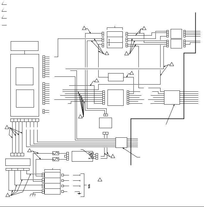
Electrical Diagrams
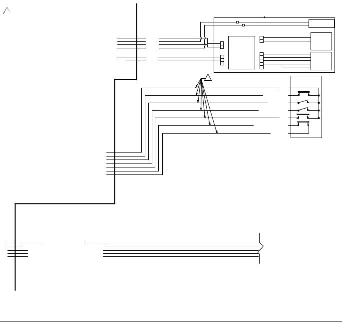
FIG. 1 shows components which must be installed in a non-hazardous location.
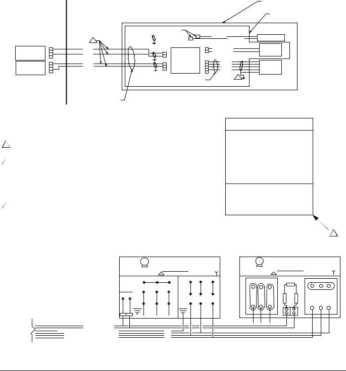
FIG. 2 shows components approved for installation in a hazardous location, and FIG. 3 shows detail views of hazardous location components.
112 Gauge Alpha Wire P/N V16012/equiv.
216 Gauge MTW Wire.
3 |
Blue/White 16 Gauge MTW Wire. |
+ |
|
||
4 |
Blue 16 Gauge MTW Wire. |
, |
|
|
|
, ' |
|
|
|
|
|
|
|
|
|
||
|
|
||
|
|
|
|
|
|||
|
|
||
|
|
||
|
|
|
! |
|
|
|
|
|
|
|
" |
|
|
|
# |
|
|
|
$ |
|
|
|
|
|
|
|
|
|
|
|
|
|
|
|
|
|
|
|
|
|
|
|
|
|
|
|
|
|
|
|
|
|
|
|
|
|
|
|
! |
|
|
|
|
|
" |
||
|
|
|
# |
|
|
$ |
|
|
|
|
|
|
|
|
|
|
|
|
|
|
|
|
|
|
|
|
|
|
|
|
|
|
|
|
|
|
|
|
* ' |
|
|
|
' |
|
|||
!
%
& ' (
& '
' )
|
|
|
|
|
|
|
|
|
|
|
|
|
|
! |
|
|
|
|
|
|
|
|
" |
|
|
# |
/ ' |
|
$ |
|
|
|
|
|
|
|
|
|
|
|
|
|
( |
|
|
||
|
|
|
|
||
|
|
|
* |
||
|
|
|
|
||
|
|
|
|
||
|
|
|
|
|
|
|
|
||
|
|
|
|
% |
|
|
|
|
% |
|
||||
|
|
|
|
% |
|
|
|
|
|
|
|
|
|
|
|
|
|
|
|
|
|
|
||
|
|
|||
|
|
|
||
, |
|
|
|
|
|
|
|
|
|
|
|
* |
||
|
|
-.- |
||
|
-! .- |
|||
|
|
|||
|
|
|
' |
||
|
|
|
|
|
# |
& & |
|
( |
|
|
|
" |
|
|
|
|
|
|
|
|
|
|
|
|
|
! |
|
|
|
|
|
|
|
||
|
|
|
|
|
||
|
|
|
|
& & |
|
|
|
|
|
|
|||
|
|
|
# |
|||
|
|
|
|
" |
|
|
|
|
|
|
|
|
|
|
|
|
|
! |
|
|
|
|
|
|
|
|
|
|
|
|
|
|
|
|
|
|
|
|
|
|
|
|
|
|
|
|
|
|
|
|
|
|
|
|
|
|
|
|
|
|
|
|
|
|
|
|
|
|
|
|
|
|
|
|
|
|
|
|
|
|
|
|
|
|
|
|
|
|
|
|
|
! |
|
|
|
|
|
|
|
|
% |
|
||
|
" |
|
||||
# |
|
|
|
|||
, |
|
|||||
$ |
/ ' |
|
' |
|
||
|
|
|
||||
|
|
|
|
|
|
|
|
|
|
|
|||
|
|
( |
|
|
|
|
% *
% % '&
-&-' 0 &
%
'
% *
/ % % '&
-&-' 0 &
IS Control Drawing 288110
FIG. 1: System Wiring Schematic, Non-Hazardous Location Only
12 |
311594Z |
Electrical Diagrams
+ |
SEE DETAIL A, |
|
|||
|
|
|
|||
6 Alpha Wire P/N M16107LW/equiv. |
|
|
|||
page 14 |
|
|
|||
|
|
|
|
|
|
|
|
|
|
|
|
|
|
|
/ |
|
|
' |
/ |
|
|
||
|
|
||||
, |
|
|
|
||
* |
|
|
|
||
, |
|
/ |
|
||
|
/ |
|
|
||
|
|
|
|
||
|
|
|
|||
|
|
||||
, |
|
|
|
|
|
|
|
|
|
|
|
|
|
|
! |
|
|
|
|
|
|
|
|
|
|
|
|
|
|
|
|
|
|
|
|
|
|
|
|
|
|
|
|
|
|
|
|
|
|
|
|
|
|
|
|
|
|
|
|
|
|
|
|
|
|
|
|
|
|
|
|
|
|
|
/ ' |
|
|
|
|
|
|
|
|
|
|
|
|
|
|
|
|
|
|
|
|
|
|
|
( |
|
|
|
|
|
|
|
|
# ' * *
# ' * *
' * ' * 1 &
, ' * 1 &
, ' * 1 &
, ' * 1 &
SEE DETAIL B, page 14
IS Control Drawing 288110
FIG. 2: System Wiring Schematic, Hazardous Location
311594Z |
13 |
Electrical Diagrams
DETAIL A
HAZARDOUS (CLASSIFIED) LOCATION
CLASS I, DIV. 1, GROUP C & D, T3 (FM ONLY)
GROUP II, CATEGORY 2 - ZONE 1, GAS (ATEX ONLY)
CLASS I, DIV. 1, GROUP C & D T3 (CANADA)
NON-HAZARDOUS |
|
|
|
|
|
INSTALLED ON PUMP ASSEMBLY |
|
|
|
|
|
|
|
||
AREA |
|
|
|
|
|
|
INSTALLED IN E-FLO JUNCTION BOX ONLY |
|
|
|
(16J588) |
|
|
|
|
|
|
|
|
|
|
+(BRN) |
POSITION SENSOR |
|
|
2 |
|
|
|
-(BLU) |
(16K088) |
|
|
|
|
|
|
|
|
|
|
|
|
|
|
J2 |
TDC |
BARRIER |
1 |
GREEN |
J2 |
|
1 |
+ (BRN) |
NAMUR |
(16A630) |
|
|
3 |
|
2 |
- (BLU) |
SENSOR |
ALL SWITCHES |
3 |
BLACK |
IS SENSOR |
|
|
(15H984) |
|
4 |
|
J1 |
|||||
"ON" POSITION 1 |
|
|
J3 |
CIRCUIT |
|
|
|
|
1 |
|
BOARD |
1 |
(RED) |
PRESSURE |
|
|
RED |
1 |
(249639) |
2 |
(GRN) |
||
BARRIER |
2 |
BLACK |
2 |
|
3 |
(WHT) |
TRANSDUCER |
(16A633) |
3 |
|
3 |
|
4 |
(BLK) |
(120371) |
|
4 |
|
|
|
5 |
|
|
5
FERRITE (16G496)
BELDEN 8777 OR EQUIV.
WITH FERRITE (123375)
1The installation must meet the requirements of the National Electric Code, Canadian Electrical Code Part I, Article 504, NFPA 70, and ANSI/ISA 12.06.01.
2Individually shielded cables needed to ensure separation of sensor and transducer circuits.
3The voltage (Vmax or Ui), current (Imax or Ii), and power (Pi) must be equal to or greater than the voltage (Voc, Uo, or Vt), current (Isc, Io, or It), and power (Po or Pt) levels, which can be delivered by the associated apparatus. In addition, the maximum unprotected capacitance (Ci) and inductance (Li) of the intrinsically safe apparatus, including interconnecting wiring, must be less than the capacitance (Ca) and inductance (La) which can be safely connected to the associated apparatus.
5 Land shield drain and foil to conductive strain relief.
|
|
|
|
DETAIL B |
|
|
|
||
|
|
|
HAZARDOUS AREA |
|
|||||
|
|
|
M |
% |
|
|
|||
|
|
|
!/$! |
|
|
|
|||
|
|
|
|
|
|
|
|
|
|
|
|
|
|
|
|
|
|
|
|
|
|
|
|
/ % |
|
|
|
||
|
|
* ' |
|
' ' |
|||||
|
|
|
|
! |
|
|
! |
|
|
|
|
|
|
|
|
|
|
||
|
* |
" |
# |
$ |
|
|
|
|
|
|
|
|
|
" |
# |
$ |
|||
|
|
|
|
|
|
|
|||
|
|
|
|
|
|
|
|
|
|
SEE PAGE 13 |
|
|
' |
|
|
' |
|
|
|
|
|
|
|
|
|
|
|
|
|
|
|
|
|
|
|
' |
|
|
|
|
# ' * * |
|
|
|
|
|
|
|
|
|
# ' * * |
|
|
' |
|
|
|
|
|
|
' * ' * 1 & |
|
|
|
|
|
|
||
, ' * 1 & |
|
|
|
|
|
|
|
|
|
|
|
|
|
|
|
|
|
||
|
, ' * 1 & |
|
|
|
|
|
|
|
|
, ' * 1 & |
|
0
2 3 !
2 3 4
2 3 4*
2 3 6
2 3 # 5
2 3 !
2 3 4
2 3 & *
2 3 & 5
2 3 & 5
3
M% %
!/$ -
|
|
/ % |
|
|
* ' |
|
' ' |
||
* |
|
|
* |
|
|
* |
|
* |
IS Control Drawing 288110
FIG. 3: System Wiring Schematic, Hazardous Location Detail Views
14 |
311594Z |
Repair
Repair
Fluid Section
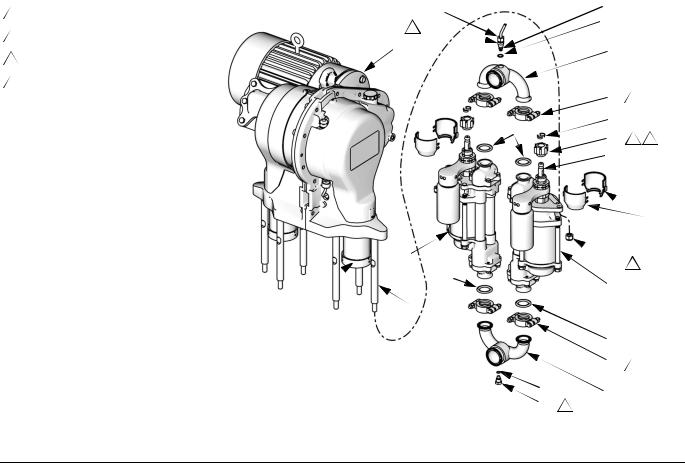
NOTE: Complete kits are available to convert from one size lower to another. See the table below for available kits. Use all the new parts in the kit. The kits include two lowers, inlet/outlet manifolds, connecting hardware, and instruction manual 311611.
Kit Part |
Lower |
|
No. |
Part No. |
Description |
|
|
|
289553 |
24F417 |
750 cc, Chrome |
15J747 |
24F428 |
1000 cc, Chrome |
15J748 |
24F436 |
1500 cc, Chrome |
15J749 |
24F444 |
2000 cc, Chrome |
16F420 |
24F418 |
750 cc, MaxLife |
15J750 |
24F429 |
1000 cc, MaxLife |
15J751 |
24F437 |
1500 cc, MaxLife |
15J752 |
24F445 |
2000 cc, MaxLife |
NOTE: Manifold Gasket Kit 15H878 is available to replace the sanitary gaskets at the inlet and outlet manifolds. The kit includes items 16, 41, 58, two 120631 PTFE Gaskets, and instruction sheet 406637.
Disassembly
1.Flush the pump, see page 9.
2.Jog the motor to bring the lower on the side being repaired to the bottom of its stroke. This provides access to the coupling nut (14).
3.Relieve pressure, page 9.
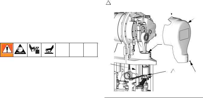
4.Remove the 2-piece shield (72, see FIG. 5) by inserting a screwdriver straight into the slot, and using it as a lever to release the tab. Repeat for all tabs. Do not use the screwdriver to pry the shields apart.
5.See FIG. 4. Place a 3/4 in. wrench on the slider piston (9) flats (just above the coupling nut), to keep the slider piston/connecting rod from turning when you are loosening the coupling nut (14). Orient the wrench so it is braced against one of the tie rods (3). Applying excessive force to the slider piston/connecting rod can shorten the life of the lower pin bearing.
6.Using a 1-5/8 in. open-end wrench, unscrew the coupling nut (14) from the slider piston (9) and let it slide down onto the pump piston rod. Be careful not to lose the collars (13).
7.Repeat steps 2-6 for the other lower.
8.Shut off electrical power and allow the unit to cool.
10Hold slider piston (9) flats with 3/4 in. wrench, and brace against tie rod (3).
32
9
3
 9 10
9 10
12
 14
14
ti9223c
FIG. 4. Remove Coupling Nut
311594Z |
15 |
Repair
9.Disconnect the fluid inlet and outlet lines from the pump. Plug the ends to prevent fluid contamination.
10.See FIG. 5. On pumps with a sensor circuit: At the pump outlet manifold (17), loosen the nut (M) on the sensor conduit (44) and unscrew the adapter (42) from the manifold. Remove the transducer (25a) from the manifold port. Remove the existing o-ring (41) and discard.
11.Loosen the clamps (18) at the inlet and outlet manifolds (17). Remove the manifolds and gaskets (16).
12.Remove the coupling nut (14) and collars (13) from the piston rods (PR).
13.Unscrew the locknuts (15). Remove the lower (22). See your separate lower manual for repair instructions.
4Torque to 50-60 ft-lb (68-80 N•m).
5Torque to 75-80 ft-lb (102-108 N•m).
7 |
Torque to 15-20 ft-lb (21-27 N•m). |
14 |
Apply lithium grease. |
7 |
M |
25a |
|
|
7 |
42 |
41 |
|
|
|
|
|
||
1 |
|
17 |
|
|
|
|
|
|
|
|
|
18 |
7 |
|
|
|
13 |
|
|
|
|
16 |
|
|
|
|
14 |
5 |
14 |
 PR
PR
 72
72
22 |
15 |
4 |
|
||
|
16 |
|
|
22 |
|
9 |
3 |
|
16 |
|
18 |
7 |
41 |
17 |
|
45 7 |
||
ti8720c |
||
|
FIG. 5: Fluid Section
16 |
311594Z |
Loading...