


 Loading...
Instructions-Parts
Integrated Air
Control Modules |
311239H |
EN |
Integrated air controls for use with NXT® Model 2200, 3400, and 6500 Air Motors. For professional use only.
100 psi (0.69 MPa, 6.9 bar) Maximum Regulated Working Pressure
NXT011, Series E
With locking air regulator and 110 psi (0.76 MPa, 7.6 bar) relief valve
NXT021, Series E
With non-locking air regulator and 110 psi (0.76 MPa, 7.6 bar) relief valve
NXT031, Series E
With locking air regulator and 85 psi (0.58 MPa, 5.8 bar) relief valve
Important Safety Instructions
Read all warnings and instructions in this manual and in NXT air motor manual 311238. Save these instructions.
Integrated Air Control Module shown mounted on an NXT Air Motor
TI8233c
Related Manuals
Contents
Related Manuals . . . . . . . . . . . . . . . . . . . . . . . . . . . |
2 |
Parts . . . . . . . . . . . . . . . . . . . . . . . . . . . . . . . . . . . . |
12 |
Warnings . . . . . . . . . . . . . . . . . . . . . . . . . . . . . . . . . |
3 |
Accessories . . . . . . . . . . . . . . . . . . . . . . . . . . . . . . |
13 |
Installation . . . . . . . . . . . . . . . . . . . . . . . . . . . . . . . . |
4 |
Schematic Diagram . . . . . . . . . . . . . . . . . . . . . . . . |
14 |
Operation . . . . . . . . . . . . . . . . . . . . . . . . . . . . . . . . . |
5 |
Technical Data . . . . . . . . . . . . . . . . . . . . . . . . . . . . |
15 |
Troubleshooting . . . . . . . . . . . . . . . . . . . . . . . . . . . . |
7 |
Graco Standard Warranty . . . . . . . . . . . . . . . . . . . |
16 |
Repair . . . . . . . . . . . . . . . . . . . . . . . . . . . . . . . . . . . . |
9 |
Graco Information . . . . . . . . . . . . . . . . . . . . . . . . . |
16 |
Related Manuals
Manuals are available at www.graco.com.
This manual is available in the following languages:
Manual |
Language |
|
|
3A0081 |
Chinese |
|
|
3A0082 |
Danish |
|
|
3A0083 |
French |
|
|
3A0084 |
Finnish |
|
|
3A0085 |
German |
|
|
3A0086 |
Greek |
|
|
3A0087 |
Italian |
|
|
3A0088 |
Japanese |
|
|
3A0089 |
Korean |
|
|
3A0090 |
Norwegian |
|
|
3A0091 |
Polish |
|
|
3A0092 |
Portuguese |
|
|
312917 |
Russian |
|
|
313800 |
Spanish |
|
|
3A0093 |
Swedish |
|
|
3A0094 |
Turkish |
|
|
2 |
311239H |
Warnings
Warnings
The following warnings are for the setup, use, grounding, maintenance, and repair of this equipment. The exclamation point symbol alerts you to a general warning and the hazard symbols refer to procedure-specific risks. Refer back to these Warnings. Additional, product-specific warnings may be found throughout the body of this manual where applicable.
WARNING
PRESSURIZED EQUIPMENT HAZARD
Fluid from the gun/dispense valve, leaks, or ruptured components can splash in the eyes or on skin and cause serious injury.
•Follow Pressure Relief Procedure in this manual, when you stop spraying and before cleaning, checking, or servicing equipment.
•Tighten all fluid connections before operating the equipment.
•Check hoses, tubes, and couplings daily. Replace worn or damaged parts immediately.
PERSONAL PROTECTIVE EQUIPMENT
You must wear appropriate protective equipment when operating, servicing, or when in the operating area of the equipment to help protect you from serious injury, including eye injury, inhalation of toxic fumes, burns, and hearing loss. This equipment includes but is not limited to:
•Protective eyewear
•Clothing and respirator as recommended by the fluid and solvent manufacturer
•Gloves
•Hearing protection
EQUIPMENT MISUSE HAZARD
Misuse can cause death or serious injury.
•Do not operate the unit when fatigued or under the influence of drugs or alcohol.
•Do not exceed the maximum working pressure or temperature rating of the lowest rated system component. See Technical Data in all equipment manuals.
•Use fluids and solvents that are compatible with equipment wetted parts. See Technical Data in all equipment manuals. Read fluid and solvent manufacturer’s warnings. For complete information about your material, request MSDS forms from distributor or retailer.
•Check equipment daily. Repair or replace worn or damaged parts immediately with genuine Graco replacement parts only.
•Do not alter or modify equipment.
•Use equipment only for its intended purpose. Call your Graco distributor for information.
•Route hoses and cables away from traffic areas, sharp edges, moving parts, and hot surfaces.
•Do not kink or over bend hoses or use hoses to pull equipment.
•Keep children and animals away from work area.
•Comply with all applicable safety regulations.
311239H |
3 |
Installation
Installation
Air Control Modules NXT011 and NXT031 (locking 
 air regulator) and NXT021 (non-locking air regula-
tor) are available.
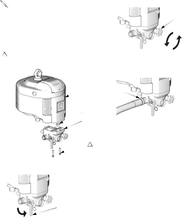
1.Install supplied o-ring (43) into counterbore on upper side of air control module (D). Fasten module to air motor (M) with two supplied screws (44). Start threading screws by hand before using a tool. Torque to 20 ft-lb (27.1 N•m).
1Screws are thread-forming. Start threading by hand before using a tool. Torque to 20 ft-lb (27.1 N•m).
3. Turn air regulator knob (C) fully counterclockwise.
 C
C
TI8322c
4.Hold the 3/4 npt(f) air inlet fitting (A) with a 1-5/16 in. wrench to prevent it from turning while securely connecting the air supply hose.
 M A
M A
43 |
TI8235c |
D |
|
 44 1
44 1
TI8323c
2. Close bleed-type master air valve (B).
 B
B
TI8322c
4 |
311239H |

Operation
Component Identification
Air Control Modules NXT011 and NXT031 (locking 
 air regulator) and NXT021 (non-locking air regula-
tor) include air line components in an integrated assembly. See FIG. 1.
Operation
Key for FIG. 1
AAir Inlet, 3/4 npt(f)
BBleed-type Master Air Valve
CAir Regulator Adjustment Knob (locking or non-locking)
DAir Pressure Gauge
EAir Filter (partially hidden)
FSafety Relief Valve
Bleed-type Master Air Valve (B)
Trapped air can cause the pump to cycle unexpectedly, which could result in serious injury from splashing or moving parts.
The bleed-type master air valve is required in your system to relieve air trapped between it and the air motor when the valve is closed.
Air Regulator (C)
Adjusts air pressure to the motor and fluid outlet pressure of pump. View the gauge (D) to read air pressure.
Air Filter (E)
Removes harmful contaminants from entering the air control module and air motor.
Safety Relief Valve (F)
Automatically opens to relieve air pressure, to prevent pump overpressurization.
C
A |
|
E |
D |
B |
F |
|
TI8233c |
FIG. 1: Air Control Module Mounted on NXT Air Motor
311239H |
5 |
Loading...