


231-055

INSTRUCTIONS-P
Parts
This
manual contains
INSTRUCTIONS and WARNINGS.
READ AND RETAIN FOR REFERENCE.
ELECTRIC, 120 VAC
ARTS LIST
IMPORTANT
307–758
Supersedes
Rev. R
Rev
. P
ULTRA
2750
psi (195 bar) MAXIMUM WORKING PRESSURE
500 AIRLESS P
Model 231–032, Series C
Basic
sprayer on Upright cart
Model 231–041, Series B
Complete
RAC IV DripLess
sprayer on Upright cart, hoses, gun,
T
ip Guard and SwitchT
ip
Model 231–054, Series D
Basic
sprayer on Lo-Boy cart without hose or gun
Model 231–055, Series B
Complete
RAC IV DripLess
U.S. PA
PATENTED 1983, CANADA
AND OTHER PATENTS PENDING
sprayer on Lo-Boy cart, hoses, gun,
T
ip Guard and SwitchT
TENT NO. 4,323,741, 4,397,610
ip
AINT SPRA
YER
NOTE: This
Spray
in confined areas can result in fire or explosion.
uids
Use outdoors or in extremely well ventilated areas. Ground equip
ment,
Avoid
cloths,
rettes,
light switches on and off.
ing
Failure
is an example of the DANGER label on your sprayer
This label is available in other languages, free of charge.
See page 46 to order
painting,
hoses, containers and objects being sprayed.
all ignition sources such as
open flames
arcs from
to follow this warning can result in death or serious injury
flushing or cleaning equipment with flammable liq
such as pilot lights, hot objects such as ciga
connecting or disconnecting power cords or turn
READ AND UNDERSTAND ALL LABELS AND INSTRUCTION MANUALS BEFORE USE
.
FIRE
AND
EXPLOSION HAZARD
static electricity from plastic drop
GRACO INC. P.O. BOX 1441
COPYRIGHT
.
SKIN INJECTION
HAZARD
Liquids
-
-
-
-
.
MINNEAPOLIS, MN
1986, GRACO INC.
can be injected into the body by high
or
leaks – especially hose leaks.
Keep
body clear of the nozzle. Never stop leaks with any part of the
body.
Drain all pressure before removing parts.A
of gun by always setting safety latch when not spraying.
gering
Never spray without a tip guard.
In case of accidental skin injection, seek immediate
“Surgical
Failure to follow this warning can result in amputation or serious
injury.
T
reatment”.
55440–1441
pressure airless spray
void accidental trig
-

TABLE OF CONTENTS
INTRODUCTION 2.
WARNINGS
English 4
French 6
Spanish 8
SETUP 10
OPERATION 12
SHUTDOWN
FLUSHING
TROUBLESHOOTING
. . . . . . . . . . . . . . . . . . . . . . . . . . . . . . . . . . . . . .
Startup 12
Cleaning
GUIDELINES
Motor W
Low
Output
No
Output
Excessive
Motor
Is Hot And Runs Intermittently
Electrical
Spin Test 22.
Bridge Test 23.
. . . . . . . . . . . . . . . . . . . . . . . . . . . . . .
. . . . . . . . . . . . . . . . . . . . . . . . . . . . . . . . . . . .
. . . . . . . . . . . . . . . . . . . . . . . . . . . . . . . . . . . .
. . . . . . . . . . . . . . . . . . . . . . . . . . . . . . . . . . .
. . . . . . . . . . . . . . . . . . . . . . . . . . . . . . . . .
. . . . . . . . . . . . . . . . . . . . . . . . . . . . . . . . . . .
a Clogged T
AND CARE
on’t Operate
. . . . . . . . . . . . . . . . . . . . . . . . . . . . . .
. . . . . . . . . . . . . . . . . . . . . . . . . . . . . . .
Pressure Fluctuations
Short
. . . . . . . . . . . . . . . . . . . . . . . . . . . . . . . .
. . . . . . . . . . . . . . . . . . . . . . . . . . . . . .
ip 13.
. . . . . . . . . . . . . . . . . . . .
. . . . . . . . . . . . . . . . . . . . .
. . . . . . . . . . . . . . . . . . . . .
GUIDE
. . . . . . . . . . . . . . . . . . . . . .
. . . . . . . . . . .
. . . . . . . .
. . . . . . . . . . . . . . . . . . . . . . . . . . .
14.
15.
16.
19.
20.
20.
21.
21.
REPAIR
General
Motor
Power
On/Off
Bridge
Circuit
Circuit
Pressure
Pressure
Drive
Motor 34
Displacement
PARTS
Displacement Pump
Upright
Lo-Boy
Pressure
Wiring
ACCESSORIES 46
TECHNICAL
DIMENSIONS 47
GRACO
THE
GRACO W
Repair Information
Brush
Supply Cord
Switch
Rectifier
Breaker
Board
Housing, Conn Rod, Crankshaft
. . . . . . . . . . . . . . . . . . . . . . . . . . . . . . . . . . . .
DRA
Sprayer
Sprayer
Diagram
PHONE NUMBERS
. . . . . . . . . . . . . . . . . . . . . . . . . . . . .
. . . . . . . . . . . . . . . . . . . . . . .
. . . . . . . . . . . . . . . . . . . . . . . . . . . .
. . . . . . . . . . . . . . . . . . . . . . . . . .
. . . . . . . . . . . . . . . . . . . . . . . . . . .
. . . . . . . . . . . . . . . . . . . . . . . . . . . .
Control
Control Adjustment
WINGS & LISTS
Control
DA
. . . . . . . . . . . . . . . . . . . . . . . . . . . . . . . .
ARRANTY AND DISCLAIMERS
. . . . . . . . . . . . . . . . . . . . . . . . .
Pump
. . . . . . . . . . . . . . . . . . . . . . . . . .
. . . . . . . . . . . . . . . . . . . . . . . . . .
. . . . . . . . . . . . . . . . . . . . . . . . .
. . . . . . . . . . . . . . . . . . . . . . . . . . .
. . . . . . . . . . . . . . . . . . . . . . . . . . . . . .
TA 47.
. . . . . . . . . . . . . . . . . . . . . . . . . . .
. . . . . . . . . . . . . . . .
. . . . . . . . . . . . . . .
. . . . . . .
. . . . . . . . . . . . . . . . . . . . . .
. . . . . . . . . . . . . . . . . . . . . .
. . . . . . . . . . . . . . . . . .
.
24.
25.
26.
26.
27.
27.
28.
29.
30.
32.
36.
39.
40.
42.
44.
45.
47.
48.
INTRODUCTION
ULTRA
Your
other
come
Pressure Control
The
sprayer
sensing device and a current overload circuit breaker
with
control is to control the motor speed so that the sprayer
maintains constant fluid pressure at the pump outlet.
Motor
The
tor brushes. It drives the displacement pump at the rate
needed
pressure. Working together, the pressure control and
motor
pressure
sounds like an automobile starter cranking. When the
pump
the fluid pressure stabilizes, then the motor will shut
til
self off. However, there will still be power to the sprayer
and it will stay pressurized and ready to use until you
manually
Because the motor is DC, it is less sensitive to low voltage or voltage fluctuations than an AC motor, and a
heavy gauge extension cord of up to 150 ft. (45 m) can
used.
be
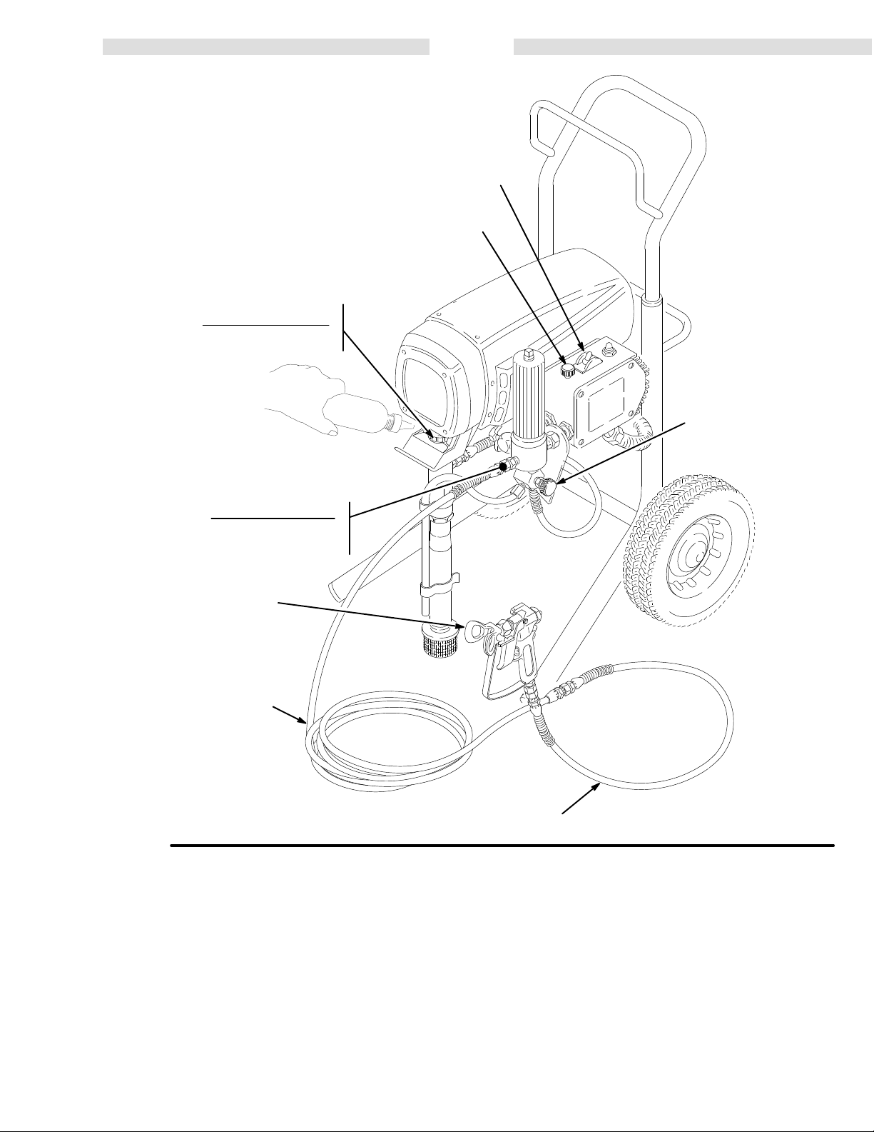
500 BASIC COMPONENTS
new sprayer functions and operates dif
airless paint sprayers. This section will help you be
familiar with the sprayer before operating it.
pressure control includes
, the pressure adjusting control knob, a pressure
a manual reset button. The function of the pressure
DC motor has sealed bearings and replaceable
to supply suf
cause the pump to cycle whenever there
demand.
is not cycling, the motor may hum intermittently un
shut it of
ficient paint volume
When the pump is cycling, the motor
f and relieve pressure.
an ON/OFF switch for the
ferently than
mo
at the selected
is fluid or
it
Drive Assembly
The
sealed drive assembly
-
motor
to the displacement pump.
transfers power from the DC
Displacement Pump
The
positive displacement, volume-balanced pump pro
equal fluid delivery on both the up
vides
strokes. The pump has a wet-cup which, when filled with
Graco Throat Seal Liquid, helps prevent damage to the
packings and piston rod.
throat
and down pump
Fluid Filter
The
fluid filter strains the paint to help avoid clogs in
hose
and spray tip. The filter includes a reusable element
and
has a pressure drain valve for manually relieving fluid
pressure.
-
Hoses
The
grounded, nylon spray hoses have spring guards on
both
ends. The 50 ft. (15.2 m) hose has a 1/4 in. ID. The
3 ft.
(0.9 m), 3/16
movement. The nylon hose material acts
dampener to absorb pressure fluctuations.
-
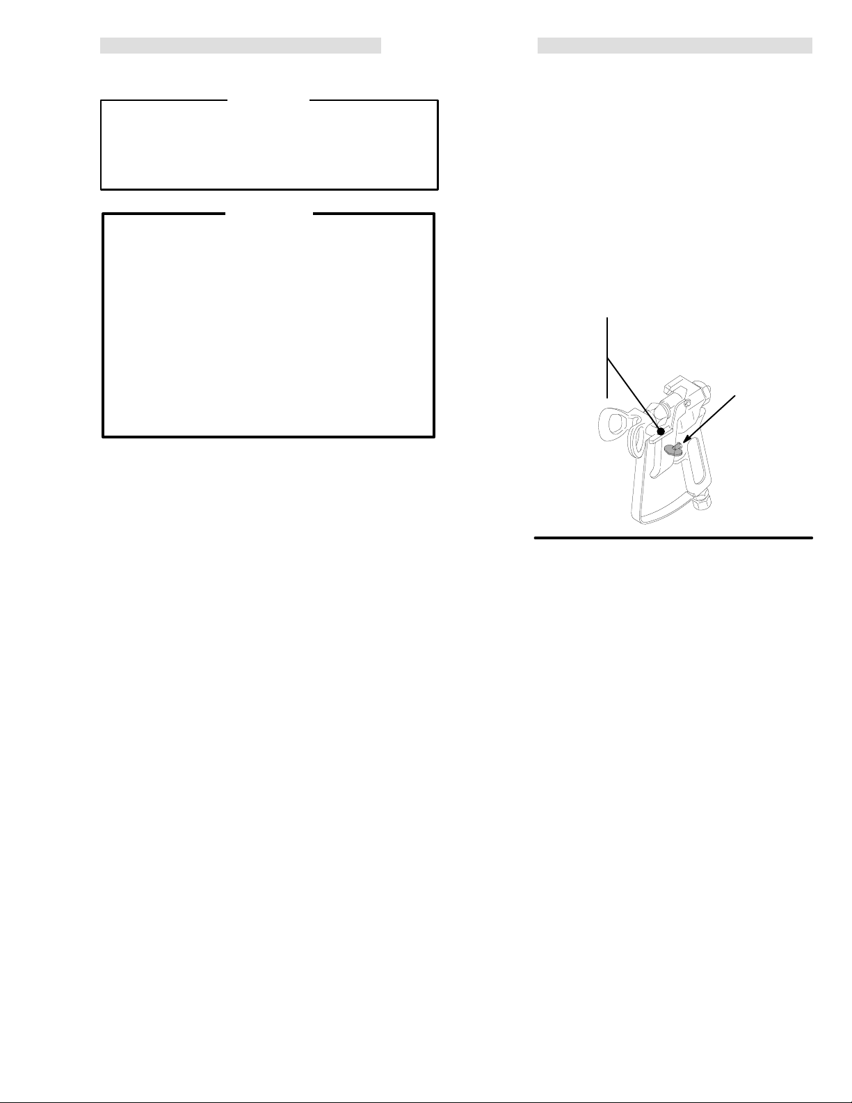
Spray Gun & RAC IV DripLess Tip Guard
Graco high pressure spray guns have a safety latch
prevents accidental
which
See the Detail in Fig 3–1. The gun provided with the
sprayer also has a filter for final paint straining. The
Reverse-A-Clean IV SwitchTip uses high pressure fluid
to remove clogs from the spray tip without removing it
from the gun. The Reverse-A-Clean IV DripLess tip
guard is a safety feature which helps reduce the risk of
injection injury
fluid
in. ID hose provides more flexible gun
as a pulsation
triggering when it is engaged.
.
-
the
2
307–758
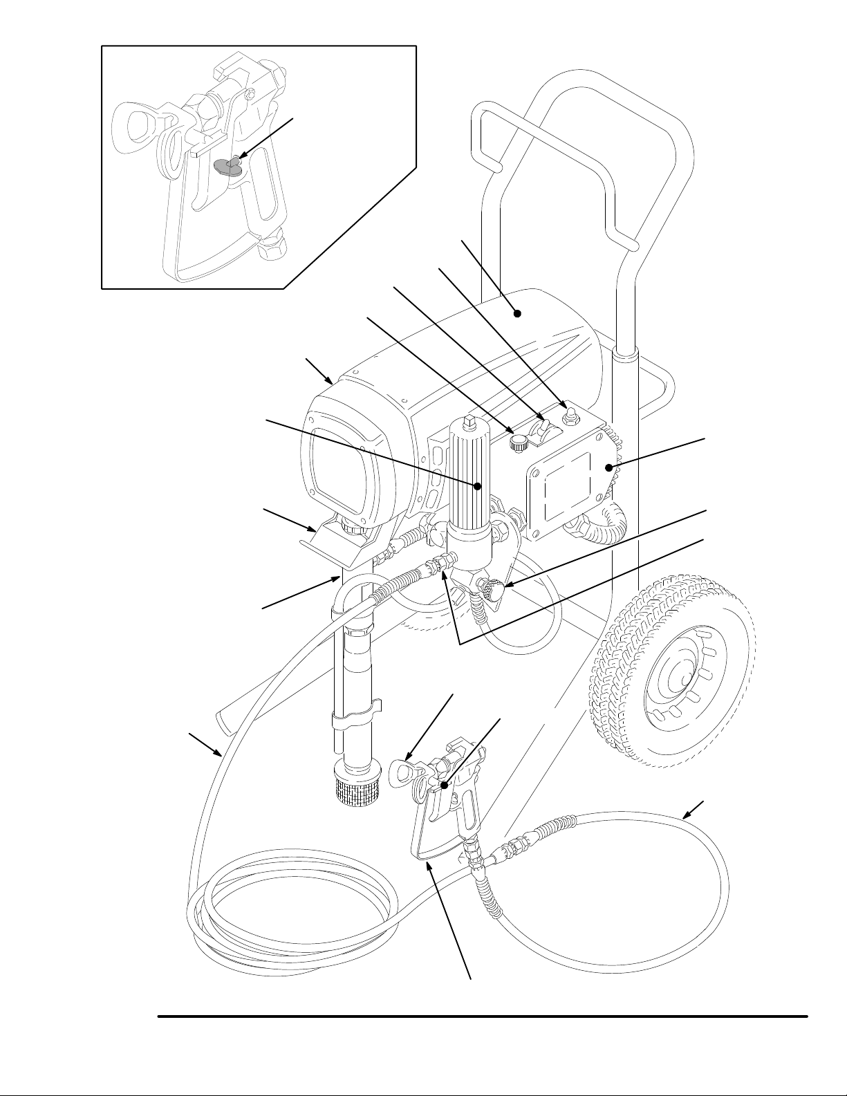
TRIGGER SAFETY
SHOWN ENGAGED
MOTOR
0137
DRIVE ASSEMBL
FLUID FIL
PAIL HANGER
DISPLACEMENT
TER
(on upright
sprayer only)
PUMP
RESET BUTT
ON/OFF SWITCH
PRESSURE
ADJUSTING KNOB
Y
ON
PRESSURE
CONTROL
PRESSURE
DRAIN
V
ALVE
FLUID OUTLET
50 FT (15 M)
MAIN HOSE
Fig 3–1
RAC IV TIP GUARD
SWITCH TIP
3 ft. (0.9 m) HOSE
CONTRACTOR GUN
01556
307–758 3
SAFETY
HIGH
PRESSURE SPRA
FOR PROFESSIONAL USE ONLY. OBSER
W
ARNINGS
Y CAN CAUSE SERIOUS INJUR
VE ALL W
ARNINGS
Y.
Read and understand all instruction manuals before operating equipment.
FLUID
INJECTION HAZARD
General Safety
This
equipment generates very high fluid pressure. Spray from
the
gun, leaks or ruptured components can inject fluid through
your
skin and into your body
ily
injury
or
age.
NEVER
NEVER put hand or fingers over the spray tip. NEVER try to
“blow back” paint; this is NOT an air spray system.
ALWAYS have the tip guard in place on the spray gun when
spraying.
ALWAYS
cleaning or removing the spray tip or servicing any system
equipment.
NEVER
Be
each
, including the need
splashed into the eyes or
point the spray gun at anyone or at any part of the body
follow the Pressure Relief Procedure
try to stop or deflect leaks with your hand or body
sure equipment safety devices are operating properly before
use.
and cause extremely serious bod
for amputation. Also, fluid injected
on the skin can cause serious dam
, below
, before
.
Medical Alert––Airless Spray Wounds
If any fluid appears to penetrate your skin, get EMERGENCY
MEDICAL CARE AT ONCE. DO NOT TREAT AS A SIMPLE
T
ell the doctor exactly what fluid was injected.
CUT.
Note
to Physician
It is important to treat the injury surgically
Do not delay treatment to research toxicity. Toxicity is a
concern with some exotic coatings injected directly into the
blood stream. Consultation with a plastic surgeon or reconstructive
:
Injection into the skin is a traumatic
hand surgeon may be advisable
as
soon as possible.
injury
.
Spray Gun Safety Devices
Be sure all gun safety devices are operating properly before
use. Do not remove or modify any part of the gun; this can
each
cause
a malfunction and result in serious bodily injury
.
Safety Latch
Whenever you stop spraying, even for a moment, always set
gun safety latch in
the
-
gun
inoperative. Failure to set the safety latch can result in acci
dental
-
triggering of the gun.
the closed or “safe” position, making the
Diffuser
.
The gun diffuser breaks up spray and reduces the risk of fluid
injection
regularly
remove
gun
the gun. If the fluid emitted
stream,
when the tip is not installed. Check dif
. Follow the
the spray tip. Aim the gun into a metal pail, holding the
firmly to the pail. Using the lowest possible pressure, trigger
replace the dif
Pressure Relief Procedure
is not
fuser immediately
diffused into an irregular
.
Tip Guard
ALWAYS have the tip guard in place on the spray gun while
spraying. The tip guard alerts you to the fluid injection hazard
helps reduce, but does not prevent, the
and
placing
your
tip.
fingers or any part of your body close to the spray
risk of accidentally
Trigger Guard
Always
have the trigger guard in place on the gun when spray
ing to reduce the risk of accidentally triggering the gun if it is
dropped
.
or bumped.
Spray Tip Safety
Use extreme caution when cleaning or changing spray tips. If
the
spray tip clogs while spraying, engage the gun safety latch
immediately. ALWAYS follow the Pressure Relief Procedure
then remove the spray tip to clean it.
and
NEVER
fully
wipe of
relieved and the gun safety latch is engaged.
f build–up around the spray tip until pressure
fuser operation
, below
, then
is
-
-
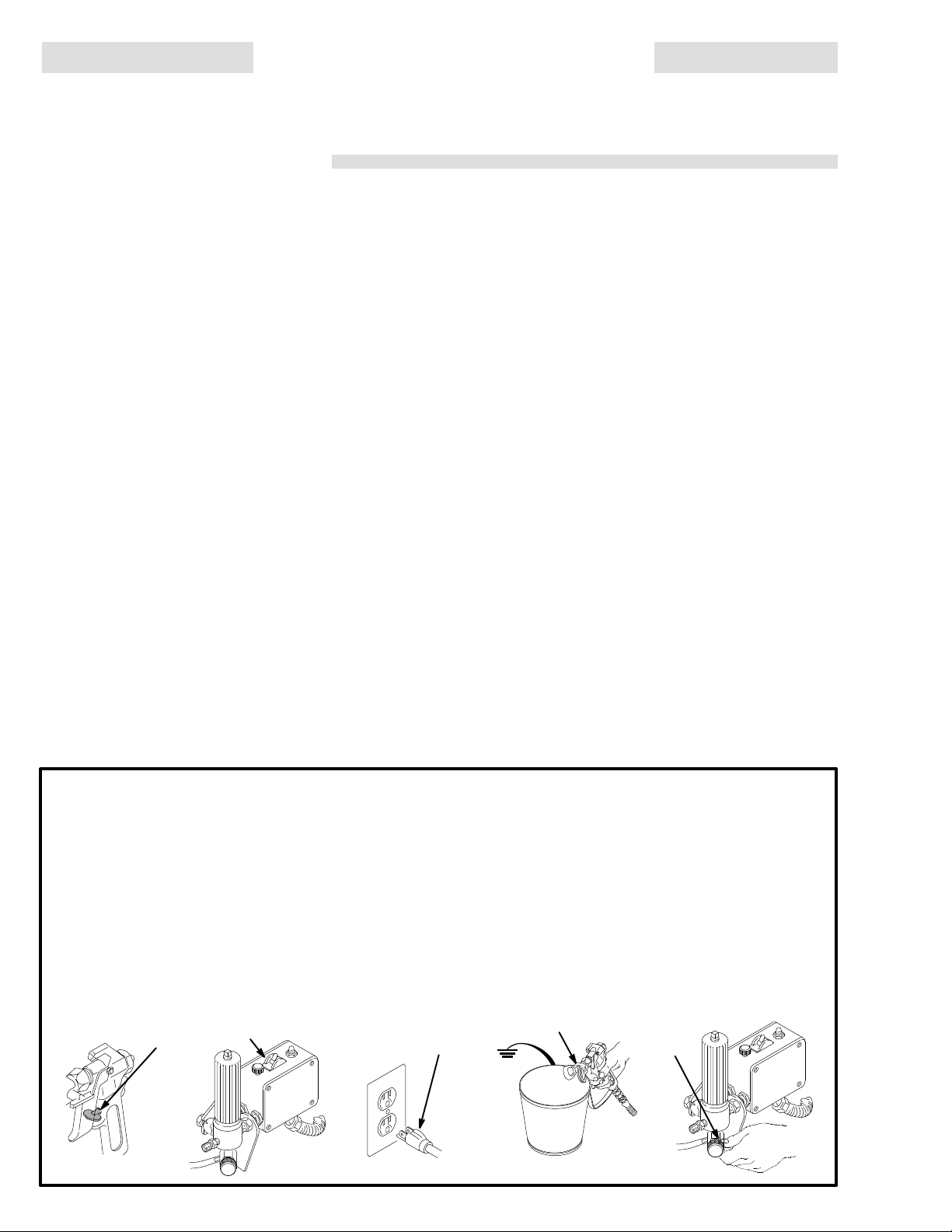
Pressure Relief Procedure
To
reduce the risk of serious bodily injury
splashing fluid or solvent in the eyes or on the skin,
jection,
or injury from moving parts or electric shock, always
this procedure whenever you shut off the sprayer, when
checking
stalling,
stop
1.
2.
3.
4
or servicing any part of the spray system, when in
cleaning or changing
spraying.
Engage the gun safety latch.
Turn the ON/OFF switch to OFF.
Unplug the power supply cord.
spray tips, and whenever you
307–758
, including fluid in
follow
4.
Disengage
-
-
gun
ger
5.
Engage the gun safety latch.
6. Open the pressure drain valve, having a container
ready
you
If you suspect that the spray tip or hose is completely
clogged,
the steps above,
lowing
retaining
ally,
then loosen completely
the gun safety latch. Hold a metal part of the
firmly to the side of a
the gun to relieve pressure.
to catch the drainage. Leave the valve open until
are ready to spray again.
or that pressure
nut or hose end coupling to
grounded metal pail, and trig
has not been fully relieved after fol
VER
Y SLOWL
. Now clear the tip or hose.
Y loosen the tip guard
relieve pressure gradu
3
6
-
-
-

MOVING P
Moving
parts
parts.
KEEP CLEAR of moving parts when starting or
the
sprayer
before checking
it
from starting accidentally
ARTS HAZARD
can pinch or amputate your fingers or other body
. Follow the
Pressure Relief Procedure
or servicing any part of the sprayer
.
operating
on page
, to prevent
EQUIPMENT MISUSE HAZARD
General Safety
Any misuse of the spray equipment or accessories, such as
overpressurizing, modifying parts, using incompatible chemicals and fluids, or using worn or damaged parts, can cause
them
to rupture and result in fluid injection, splashing in the eyes
or
on the skin, or other serious bodily injury
property
damage.
, or fire, explosion or
HOSE SAFETY
High
pressure fluid in the hoses can
2
hose develops a leak, split or rupture due to any kind of wear,
damage
cause a fluid injection injury or other serious bodily injury or
property
ALL FLUID HOSES MUST HAVE SPRING GUARDS ON
BOTH ENDS! The spring guards help protect the hose from
kinks or bends at or close to the coupling which can result in
hose
TIGHTEN
pressure
sure
or misuse, the high pressure spray emitted from it
damage.
rupture.
all fluid connections securely before each use. High
fluid can dislodge a loose coupling or allow high pres
spray to be emitted from the coupling.
be very dangerous. If the
can
-
NEVER alter or modify any part of this equipment; doing so
cause it to malfunction.
could
CHECK all spray equipment regularly and repair or replace
worn
or damaged parts immediately
Always
wear protective eyewear
tor
as recommended by the fluid and solvent manufacturer
.
, gloves, clothing and respira
.
System Pressure
This sprayer can develop
WORKING
accessories
exceed the maximum working pressure of any component or
accessory
PRESSURE. Be sure that all
used are rated to withstand this pressure. DO NOT
used in the system.
Fluid and Solvent Compatibility
All
chemicals used in the sprayer must be compatible with
wetted
parts
your chemical supplier to ensure compatibility
sult
not use 1,1,1-trichloroethane, methylene chloride, other ha
Do
logenated hydrocarbon solvents or fluids containing such solvents in this equipment, which contains aluminum and/or zinc
parts.
the possibility of explosion, which could cause death, serious
bodily
shown in the
Such
use could result in a serious chemical reaction, with
injury and/or substantial property damage.
2750 psi (190 bar)
spray equipment and
TECHNICAL DATA on page 47. Con
MAXIMUM
the
.
FIRE OR EXPLOSION HAZARD
Static
electricity is created by the flow of fluid through the pump
and hose. If every part of the spray equipment is not properly
grounded, sparking may occur, and the system may become
hazardous. Sparking may also occur when plugging in or unplugging a power supply cord or using a gasoline engine.
Sparks can ignite fumes from solvents and the fluid being
sprayed, dust particles and other flammable substances,
whether you are spraying indoors or outdoors, and can cause
a fire or explosion and serious bodily injury and property
damage.
If you experience any static sparking or even a slight shock
using this equipment, STOP SPRA
while
Check the entire system for proper grounding. Do not use the
system again until the problem has been identified and
corrected.
Grounding
To
reduce the risk of static sparking, ground the sprayer and
other spray equipment used or located in the spray area.
CHECK
tions
all
1.
your local electrical code for
for your area and type of equipment. BE SURE to ground
of this spray equipment:
Sprayer:
true
connect a ground wire and clamp
earth ground.
YING IMMEDIA
detailed grounding instruc
(supplied) to a
TELY.
all
NEVER
tire
movement of the hose couplings. If
ist, replace the hose immediately
pressure hose or mend it with tape or any other device. A repaired
HANDLE AND ROUTE HOSES CAREFULLY. Do not pull on
hoses to move equipment. Keep hoses clear of moving parts
and
or solvents which are not compatible with the inner tube and
cover
above
use a damaged hose. Before each use, check the en
hose for cuts,
hose cannot contain the high pressure fluid.
hot surfaces of the pump and gas engine. Do not use
of the hose. DO NOT
180 F (82C) or below –40 F (–40
leaks, abrasion, bulging cover
any of these conditions ex
. DO NOT try to recouple high
expose Graco hose to temperatures
C).
, or damage or
Hose Grounding Continuity
Proper
hose grounding continuity is essential to maintaining a
grounded
-
fluid
tag on it which specifies the maximum electrical resistance,
-
contact
sistance
for your hose to check the resistance. If the resistance exceeds
the recommended limits, replace it immediately. An ungrounded
ardous.
2.
3.
4.
5.
6.
7.
spray system. Check the electrical resistance of your
hoses at least once a week. If your hose does not have a
the hose supplier or manufacturer for the maximum re
limits. Use a resistance meter in the appropriate range
or poorly grounded hose can make
Also read
Fluid
hoses:
500 ft (150 m) combined hose length to
continuity.
Spray
gun:
erly
grounded fluid hose and sprayer
Object being sprayed:
Fluid supply container:
FIRE OR EXPLOSION HAZARD.
use only grounded hoses with
See
Hose Grounding Continuity.
obtain grounding through connection
according to local code.
according to local code.
All solvent pails used when flushing,
code. Use only metal pails, which are conductive. Do not
the pail on a non–conductive surface,
place
or
cardboard, which interrupts the grounding continuity
To
maintain grounding
pressure
side
,
always hold a metal part of the gun firmly to the
of a grounded metal pail, then trigger the gun.
continuity when flushing or relieving
your system haz
a maximum of
ensure
.
according to local
such as paper
Flushing Safety
Reduce the risk of fluid injection injury, static sparking, or
splashing
of
this manual. Follow the
4, and remove the spray tip before flushing. Hold a metal part
the gun firmly to the side of
of
lowest
by following the flushing procedure given on page 15
Pressure Relief Procedure
a grounded metal pail and use the
possible fluid pressure during flushing.
fluids
grounding
to a prop
.
on page
-
-
-
-
-
IMPORTANT
United
States Government safety standards have been adopted under the Occupational Safety and
particularly
the General Standards, Part 1910, and the Construction Standards, Part 1926 – should be consulted.
Health Act. These standards –
307–758 5
AVERTISSEMENT
La
pulvérisation à haute pression peut causer des blessures très graves.
Réservé exclusivement à l’usage professionnel. Observer toutes les consignes de sécurité.
Bien lire et bien comprendre tous les manuels d’instructions avant d’utiliser le matériel.
RISQUES D’INJECTION
Consignes
Cet appareil produit un fluide à très haute pression. Le fluide
pulvérisé
fuites
du
corps et entrainer des blessures très graves, voir même une
amputation.
sant ou entrant dans les yeux peut aussi entrainer des blessures graves.
JAMAIS pointer le pistolet vers quelqu’un ou
NE
quelconque
sur
l’ajutage du pulvérisateur
la peinture. Cet appareil N’est PAS un compresseur
pneumatique.
TOUJOURS
pendant la pulvérisation.
tolet
TOUJOURS observer la March à Suivre pour Détendre la
Pression donnée plus loin, avant de nettoyer ou d’enlever
l’ajutage
sur
une partie de l’appareil.
NE JAMAIS essayer d’arrêter ou de dévier les fuites avec la
main
ou le corps.
Avant chaque utilisation, bien s’assurer que les dispositifs de
sécurité
Soins
En
cas de pénétration de fluide sous la peau:
MEDIATEMENT DES SOINS MEDICAUX D’URGENCE. NE
PAS SOIGNER CETTE BLESSURE COMME UNE SIMPLE
COUPURE.
Avis
au medecin
traumatisme.
cette
ment
revêtements exotiques sont dangereusement toxiques
quand ils sont injectés directement dans le sang. Il est
souhaitable de consulter un chirurgien esthétique ou un
chirurgien
Marche
Pour réduire les risques de blessures graves, y compris les
blessures par injection de fluide ou celles causées par des
éclaboussures dans les yeux ou sur la peau, des pièces en
mouvement
marche
à
l’occasion de la vérification, du reglage ou du nettoyage du
systeme
1.
Engager le verrou de sécurité du pistolet.
2. Basculer
RET (OFF).
3.
Debrancher le cordón d’alimentation.
generales de sécurité
par le pistolet ou le fluide sous pression provenant de
ou de ruptures peut pénétrer sous la peau ou à l’interieur
Même sans être sous pression, le fluide
du corps. NE
garder la protection
du pulvérisateur, ou d’ef
fonctionnent correctement.
JAMAIS mettre la main ou les doigts
. NE JAMAIS essayer de “refouler”
de l’ajutage en place sur le pis
fectuer un travail quelconque
éclabous
vers une partie
medicaux
DEMANDER
: La pénétration des fluides sous la peau est
blessure immédiatement.
pour ef
Il est important de traiter chirurgicalement
Ne pas retarder le traite
fectuer des recherches sur la toxicité. Certains
spécialisé dans la reconstruction des mains.
IM
un
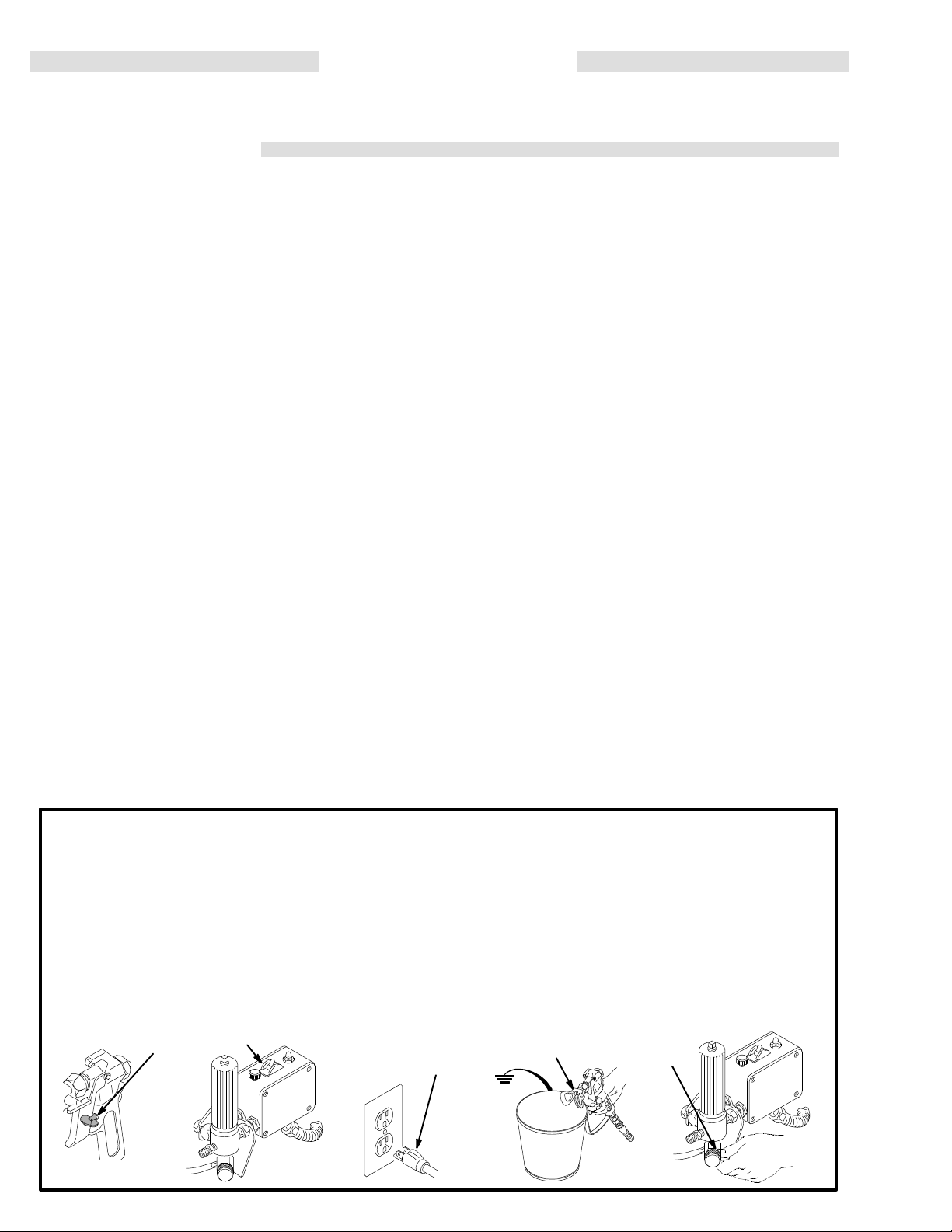
à Suivre pour Détendre la Pression
ou par électrocution, toujours bien observer cette
à suivre à chaque fois que l’on arrête le pulvérisateur
ou lors du changement des ajutages.
l’interrupteur de commande de pression sur AR
Dispositifs de sécurité du pistolet
Avant
chaque utilisation, bien s’assure que
de sécurité du pistolet fonctionnent correctement. Ne pas en-
ni modifier une partie
lever
d’entraîner un mauvais fonctionnement et des
-
Verrou
de sécurité
A chaque fois que l’on s’arrête de pulvérisér, même s’il s’agit
court instant, toujours mettre le verrou de sécurité du pis
d’un
tolet sur la position “fermée” ou “sécurité” (“safe”) pour
empêcher le pistolet de fonctionner. Si le verrou de sécurité
pas
n’est
Voir
mis, le pistolet peut se déclencher accidentellement.
la figure, ci–dessus.
quelconque du pistolet; ceci risquerait
tous les dispositifs
blessures
Diffuser
Le
dif
fuseur du pistolet sert à diviser le jet et à réduire les risques
d’injection accidentelle quand l’ajutage n’est pas en place.
Vérifier le fonctionnement du diffuseur régulièrement. Pour
vérification, détendre la pression en observant la Marche
cette
à
Suivre
lever
en
utilisant la pression la plus faible possible, appuyer sur la
gachette du pistolet. Si le fluide projete
forme
Protection
TOUJOURS
pistolet
de
bue
partie
-
ximité
pour Détendre la Pression
l’ajutage du pulvérisateur
métal, en le maintenant fermement contre le seau. Puis,
de jet irrégulier
, remplacer immédiatement le dif
de l’ajutage
maintenir la protection de l’ajutage en place sur le
du pulvérisateur pendant la
l’ajutage attire l’attention sur les risques d’injection et contri
à réduire, mais n’évite pas le risque, que les doigts ou une
quelconque du corps
immédiate de l’ajutage du pulvérisateur
ne passent accidentellement à pro
donnée plus loin puis en
. Pointer le pistolet dans un seau
n’est pas
pulvérisation. La protection
Consignes de sécurité concernant l’ajutage du
pulvérisateur
Faire extremement attention à l’occasion du nettoyage ou du
remplacement des ajutages du pulvérisateur. Si l’ajutage se
pendant la pulvérisation, mettre immédiatement le ver
bouche
rou de sécurité du pistolet. TOUJOURS bien observer la
Marche à Suivre pour Détendre la Pression puis enlever
l’ajutage
NE
du pulvérisateur avant que la pression ne soit completement
tombée
4. Désengager le verrou de sécurité du pistolet. Tout en
5.
,
6. Ouvrir
Si
-
ment bouche, ou que la pression n’a pas été complètement
libérée
serrer très LENTEMENT un raccord du bout du tuyau ou
l’écrou de retenue de la protection de l’ajutage et libérer
progressivement
3
du pulvérisateur pour le nettoyer
JAMAIS essuyer
et que le verrou
maintenant une partie métallique du pistolet fermement
appuyée contre le côté d’un seau en métal, actionner le
pistolet
pour libérer la pression.
Engager le verrou de sécurité du pistolet.
la soupape de sécurité et la laisser ouverte jusqu’a
ce
que l’on soit pret à se servir de nouveau du pulvérisa
teur
. Débrancher le fil de la bougie.
ce qui s’est accumulé autour de l’ajutage
de sécurité du pistolet ne soit engagé.
.
l’on soupçonne que le tuyau ou l’ajutage du est complète
après avoir procede aux operations ci–dessus, des-
la pression.
6
graves.
-
-
en
diffusé sous
fuseur.
-
-
.
-
-
-
6
307–758

RISQUES EN CAS DE MAUVAISE UTILISATION DU MATERIEL
Consignes
Toute
accessoires comme, par exemple, la mise sous une pression
excessive,
chimiques
usées
ruptures de pièces et entraîner une injection de liquide ou
d’autrès blessures sérieuses, un incendie, une explosión ou
d’autrès
NE
JAMAIS alterer ou modifier une piece de cet appareil; ceci
risquerait
Vérifier régulièrement tout l’appareil de pulvérisation et ses
equipements et réparer ou remplacer immédiatement les
pièces
générales de sécurité
utilisation anormale de l’appareil de
les modifications de pièces, l’utilisation de produits
et
de matières incompatibles et l’utilisation de pièces
ou abîmées peut causer des dégâts à
dégâts.
d’entraîner son mauvais fonctionnement.
usées ou abîmées.
pulvérisation ou des
l’appareil ou des
Pression
Ce
pulvérisateur peut
TRAVAIL 190 bar (2750 lb/po2). S’assurer que tous les
éléments
résister à la pression maximum de travail de ce pulvérisateur.
NE
éléments
du pulvérisateur et ses accessoires sont conçus pour
P
AS depasser la pression maximum de travail d’aucun des
ou accessoires utilisés avec cet appareil.
Compatibilité
BIEN
S’ASSURER que tous les corps des solvants utilisés sont
chimiquement
dans les Technical Data, à page 47. Toujours lire soigneuse-
les documents et brochures du fabricant des fluides et sol
ment
utilisés avant de s’en servir dans ce pulvérisateur
vants
produire une PRESSION MAXIMUM DE
chimique des corps
compatibles avec les parties mouillées indiquées
MESURES DE SÉCURITÉ CONCERNANT LES TUYAUX FLEXIBLES
Le
fluide à
dangereux.
rupture
tion,
peuvent entraîner des blessures graves par pénétration sous
peau ou par contact, ainsi que des dégâts matériels.
la
TOUS
SORTS SPIRALE DE PROTECTION AUX BOUTS! Les
spirales
de
la
rupture du tuyau à l’endroit du raccord ou à son voisinagé.
SERRER
tion. Le fluide sous pression peut faire sauter un raccord desserre
cord.
NE
refaire le raccord d’un tuyau haute pression ni de réparer le
tuyau
réparé
haute pression circulant dans les tuyaux peut être très
En cas de fuite sur le
à la suite de l’usure, de dégâts ou
les projections de fluide haute pression qui en proviennent
LES TUY
de protection
boucles ou de nœuds sur
ou produire un jet à haute pression s’échappant par le rac
JAMAIS utiliser un tuyau endommagé. NE P
avec du ruban adhesif
ne peut pas résister au fluide sous pression.
AUX FLEXIBLES DOIVENT A
contribuent à eviter la formation de pliures,
FERMEMENT tous les raccords avant chaque utilisa–
tuyau, de fissure, déchirure ou
d’une mauvaise utilisa
VOIR DES RES
les tuyaux qui pourraient entraîner
AS essayer de
ou par tout autre moyen. Un tuyau
MANIPULER
SOIGNEUSEMENT
-
en
tirant sur le tuyau. Ne pas utiliser de fluides
qui ne sont pas compatibles avec l’enveloppe intérieure ou
extérieure
supérieures
Continuité
-
Une
bonne continuité de la mise à la terre des tuyaux est
pour maintenir la mise à la terre de l’ensemble de vaporisa
tielle
Vérifiez la résistance électrique de vos tuyaux à fluides et
tion.
à
air
, au moins une fois par semaine. Si votre tuyau ne comporte
pas d’étiquette qui précise la résistance électrique maximum,
prenez contact avec le fournisseur de tuyaux ou la fabricant
avoir les límites de résistance maximum. Utilisez un mètre
pour
-
de
résistance de la gamme appropriée pour votre tuyau et véri
fiez la résistance. Si celle-ci dépasse les límites recommandées, remplacez le tuyau immédiatement. Un tuyau sans
à la terre ou avec une mise à la terre incorrecte peut en
mise
traîner des risques pour votre systeme. Lisez aussi LES
RISQUES D’INCENDIE OU D’EXPLOSIÓN ci-dessus.
LES TUY
du tuyau. N
à 8
AUX A
LEUR CHEMIN. Ne pas
E PAS e
2C (180F
de la mise à la terre des tuyaux
RISQUES D’INCENDIE OU D’EXPLOSIÓN
De
l’électricité statique est produite par le passage du fluide à
grande
vitesse dans la pompe et dans les tuyaux. Si toutes les
pieeces de l’appareil de pulvérisation ne sont pas convenable
reliées à la masse ou à la terre, des étincelles peuvent se
ment
produire et l’appareil risque d’être dangereux. Des étincelles
peuvent également se produire à l’occasion du branchement
du débranchement du cordón d’alimentation. Les
ou
sont
suf
fisantes pour allumer les vapeurs de solvants et le fluide
pulvérisé,
substances
l’extérieur, et elles peuvent causer un incendie ou une explosión, ainsi que des blessures graves et des dégâts matériels.
Toujours brancher le pulvérisateur dans une prise se trouvant
au moins 6 m (20 pieds) de l’appareil et de l’endroit où se fait
à
la pulvérisation. Ne pas brancher ou débrancher un cordón
d’alimenations
sation quand il y à le moindre risque que des vapeurs encore
présentes
S’il
sentez
PULVÉRISATION. Vérifiez que le système entier est bien mis
à laterre. Ne vous servez pas du système avant que le
problème
Mise
Pour
statique,
trouvant dans la zone de pulvérisation doivent être reliés à la
terre
mise
CONSULTER le code ou les réglementations électriques locales.
suivants
1.
les fines particules de poussieère ainsi que d’autrès
inflammables, quand on pulvérisé à l’intérieur ou à
quel qui’il soit dans la zone où se fait la pulvéri
dans l’air prennent feu.
se produit des étincelles d’électricité statique, ou si vous res
la moindre décharge, ARRÊTEZ IMMÉDIA
soit identifié et corrigé.
à la terre ou à la masse
réduire les risques de production d’étincelles d’électricité
le pulvérisateur et tous les équipements utilisés ou se
ou à la masse.
à la terre dans la region et le type particulier d’équipement,
S’ASSURER que tous les équipements de
sont bien reliés à la terre:
Pulvérisateur:
qui doivent être équipés d’une prise à 3 fiches en bon
longe
état,
dans une prise de courant convenablement mise à la
terre. Ne pas utiliser d’adaptateur. Toutes les rallonges
doivent
avoir 3 fils et être prevues pour 15 ampères.
Pour connaître le detail des instructions de
Brancher le cordón d’alimentation ou la
étincelles
TEMENT LA
pulvérisation
ral
2.
Tuyaux flexibles:
terre, n’utiliser que des tuyaux comportant une mise à la
-
-
-
la
terre
et ayant une longueur maximum combinée de 150 m
(1500
pieds). Se reporter également au paragraphe
nuité
du circuit de mise à la terre des tuyaux.
3.
Pistolet
: Réaliser la mise à la terre en le raccordant à un
tuyau flexible et à un pulvérisateur dèjá convenablement
à la terre.
reliés
4.
Récipient d’alimentation:
mentations
5.
Objets,
matériel ou surfaces reçevant la pulvérisation:
le code ou les réglementations locales.
server
6.
Tous les seaux de solvants
server le code ou les réglementations locales. N’utiliser
que des saux métalliques conducteurs
pas
mettre le seau sur une surface non conductrice
sur du papier ou du carton car cela interromprait la conti-
de la mise à la terre.
nuité
7.
Pour
conserver la continuité de la mise à la terre quand on
Afin d’assurer la continuité de la mise à
locales.
rince le matériel ou quand on libére la pression
maintenir
puyée
la
Mesures
Pour réduire les risques de blessures par pénétration de la
peau et les risques dûs aux etincelles d’electricite statique ou
éclaboussures, observer la marche à suivre
aux
donnée à la page 15 de ce manuel. Observer la “Marche à
-
Suivre pour Détendre la Pression” donnée à la page 6 en
l’ajutage du pulvérisateur
lever
partie
métallique
d’un
seau en métal et utiliser la pression la plus faible possible
pendant
une partie métallique du pistolet fermement ap
contre le côté d’un seau en métal puis appuyer sur
détente du pistolet.
de sécurité concernant le Rincage
du pistolet fermement appuyée contre le côté
le rincage.
.
VEC PRECAUTION ET CHOISIR
xpose
r l
) o
e t
u i
nférieure
observer le code ou les régle-
utilisés pour le rinçage: ob-
avant le rincage
déplacer le fluide
ou de solvants
uya
u à des t
s à –
empératures
40C (–40F).
de l’électricité. Ne
pour le rincage
. Maintenir une
essen
Conti-
comme
, toujours
307–758 7
ob
en-
-
-
-
-
-
-
-
ADVERTENCIA
EL
ROCIADO a ALTA PRESIÓN PUEDE CAUSAR GRA
SOLO P
Lea y entienda todo el manual de instrucciónes antes de manejar el equipo.
PELIGRO DE INYECCIÓN DE FLUIDO
Seguridad
Este
equipo genera un fluido a una presión muy alta. El rociado
de la pistola, los escapes de fluido o roturas de los componentes
lesiones extremadamente graves, incluyendo a veces la
necesidad de amputación. También, el fluido inyectado o salpicado
NUNCA apuntar la pistola hacia alguien o alguna parte del
cuerpo.
quilla.
un
sistema de rociado de aire.
SIEMPRE tener colocado el protector de la boquilla en la pistolamientras
SIEMPRE seguir el procedimiento de descarga de presión,
dado
vicioa
NUNCA
cuerpo.
Asegurar
funciónando
Tratamiento
Si pareciera que un poco de fluido penetró la piel, conseguir
TRATAMIENTO MÉDICO DE URGENCIA DE INMEDIATO.
NO
TRATAR LA HERIDA COMO UN SIMPLE CORTE.
al
médico exactamente cua fluido fue.
A
viso al médico:
causa
mente la lesión a la brevedad posible. No demorar el
tratamiento
suma importancia en algunas pinturas exóticas cuando se inyectan directamente al torrente sanguineo. Sirá conveniente
consultar
de
las manos.
general
pueden inyectar fluido en la piel y el cuerpo y causar
en los ojos puede causar graves daños.
NUNCA colocar la mano o los
NUNCA
másabjo, antes de
cualiquier equipo del sistema.
tratar de “hacer retornar la pintura”; este NO es
se está pulverizando.
tratar de parar o desviar los escapes
que todos los aparatos de seguridad del equipo están
bien antes de cada uso.
médico
una lesión traumática.
Si se llega a inyectar este fluido en la piel se
para investigar la toxicidad. La toxicidad es algo de
a un especialista en cirugia plástica o reconstructiva
ARA USO PROFESIONAL. RESPETE LOS A
dedos encima de la bo–
limpiar o sacar la boquilla o de dar ser
con la mano o el
Decir
Es importante tratar
quirúrgica
VES LESIONES.
VISOS DE ADVERTENCIA.
Aparatos
Asegurar
funciónando bien antes de cada uso. No sacar ni modificar
ningúna
miento
Pestillo
Cada
momento, siempre colocar el pestillo de seguridad en la posición “cerrada” lo que deja la pistola inoperante. El no hacerlo
puede
Difusor
El
difusor de la pistola dispersa el chorro pulverizado y reduce
el riesgo de inyección cuando no está instalada la boquilla.
Revisar
procedimiento de descarga de presión, dado más abajo, y
-
después
sosteniéndola bien firme contra el. Utilizando la presión más
co,
bajo
perso
Protector
SIEMPRE
mientras
contra
la
colocación accidental de los dedos o cualquier otra parte del
cuerpo
Seguridad
Tener
ra a obstruirse mientras está pulverizando,
-
tillo de la pistola de inmediato. SIEMPRE seguir el procedimiento de descarga de presión y después sacar la boquilla
para
NUNCA
quilla
y
el pestillo este enganchado.
de seguridad de la pistola pulverizadora
que todos los aparatos protectores de la pistola están
pieza de la pistola pues podria causar el malfuncióna
de
la misma con las consiguientes lesiones personales.
de seguridad
vez que se deje de pulverizar
llevar al disparo imprevisto de la pistola.
con regularidad el
sacar la boquilla. Apuntar la pistola a un balde metáli
posible, disparar la pistola. Si el fluido emitido no sale dis
en un
chorro irregular
funciónamiento del difusor
, reemplazar de inmediato el difusor
, aunque sea por un breve
de la boquilla
tener
el protector de la boquilla colocado en la pistola
se está pulverizando.
el peligro de inyección
cerca de la boquilla.
Este protector llama la atención
y ayuda a reducir
de la boquilla pulverizadora
mucho cuidado al limpiar o cambiar las
limpiarla.
limpiar la acumulación de pintura alrededor de la bo–
antes de que se haya descargado por completo la presión
boquillas. Si llega
enganchar el pes
-
. Seguir el
-
.
, pero no evita,
-
-
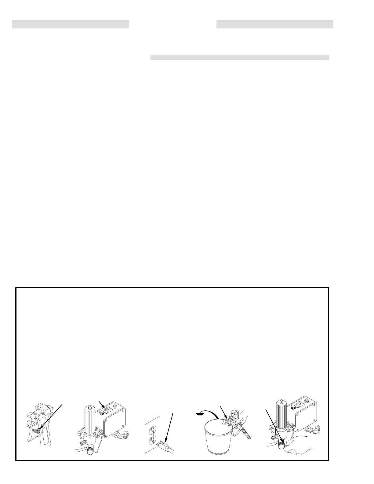
Procedimiento
Para
reducir el riesgo de
cluyendo inyección o lesiones causadas por piezás en
movimiento o choque eléctrico, siempre seguir este
procedimiento
o
dar servicio a cualquier
al
instalar
deja
1.
2. Mover
3. Desenchufar
4.
8
, limpiar o cambiar las boquillas, y cada vez que se
de pulverizar
Enganchar el pestillo de la pistola.
el interruptor eléctrico (ON/OFF) a la posición OFF
(apagado).
Desenganchar el pestillo de la pistola. Sujetar una parte
metálica
y
disparar la pistola para descargar la presión.
307–758
de descarga de presión
sufrir graves lesiones corporales, in
al apagar la máquina pulverizadora, al revisar
el cordón electrico.
de la pistola
parte del sistema de pulverización,
.
bien firme contra un balde de metal,
5.
Enganchar el pestillo de la pistola.
-
6. Abrir
Si se sospecha que la boquilla o la manguera está completamente obstruida, o que no se ha descargado por completo
anterior, aflojar MUY LENTAMENTE la tuerca de retención
del
manguera y descargar gradualmente la presión, después,
aflojarlo por completo. Luego, despejar la boquilla o la
manguera.
3
la válvula de presión y tener listo un reclipiente
recibir la pintura. Dejar la válvula de alivio de presión
abierta hasta que se este nuevamente listo para pulverizar.
la
presión después de haber seguido el procedimiento
protector de la boquilla o acoplamiento
6
de la punta de la
para

PELIGRO POR MAL USO DEL EQUIPO
Seguridad
Cualquier
como sobre presurización, modificación de piezás, uso de
matériales
piezás dañadas o desgastadas, puede hacen que se rompan
y causen la inyección de fluido u otras lesiones corporales
graves,
NUNCA alterar o modificar ningúna pieza de este equipo; el
hacerlo
REVISAR con regularidad el equipo pulverizador y reparar o
reemplazar
general
mal uso del equipo pulverizador o los accesorios, tal
y productos quimicos incompatibles, o utilización
incendio, explosión o dañon a la propiedad.
podria causar una avería.
de inmediato las piezás dañadas o desgastadas.
de
SEGURIDAD EN EL USO DE LAS MANGUERAS
El fluido que escapa a alta presión por las mangueras puede
muy peligroso. Si en la manguera se desarrolla un
ser
una
rotura o rajadura debido a cualquier tipo de desgaste, daño
o maltrato, el chorro a alta presión emitido por alli puede causar
una lesion por inyección u otras lesiones corporales graves o
a la propiedad.
daños
!TODAS LAS MANGUERAS PARA FLUIDOS TIENEN QUE
TENER
Estas
en los acoplamientos o cerca de ellos, los que podrian
traducirse
Antes
El fluido a alta presión puede desalojar un acoplamiento suelto
o
NUNCA usar una manguera que está dañada. Siempre,
revisarla
abultada, o acoplamientos sueltos o dañados. Si llegara a en
contrarse cualquiera de estás condiciónes, reemplazar de inmediato la manguera. NO intentar racoplar una manguera de
alta presión o enmendarla con cinta adhesiva u otro matérial
similar. Una manguera que ha sido remendada no aguante el
fluido
GUARDAS DE RESORTE EN AMBOS EXTREMOS!
protegen las
en roturas de la manguera.
de usarlas, APRET
dejar que por el escape un chorro a alta presión.
en busca de cortaduras, escapes, abrasion, cubierta
a alta presión.
mangueras contra dobleces o retorceduras
AR bien firmes
todas las conexiones.
escape,
-
Presión
está
presión DE TRABAJO MÁXIMA.
pulverizador
tar la presión máxima de trabajo de está pulverizadora. NO ex
ceder la presión máxima de trabajo de ningún componente o
accesorio
del sistema
pulverizadora puede desarrollar
y sus accesorios
de este sistema.
Asegurar que todo el equipo
tienen la capacidad para aguan
190 barías (2750 psi) de
Compatibilidad de fluido
Siempre leer las instrucciónes del fabricante del fluido y solvente
antes de usarlos en está
na
47.
Siempre usar gafas, guantes, vestimetas protectora y un
respiradero,
del solvente.
MANEJAR Y PASAR CUIDADOSAMENTE LAS MANGUERAS.
usar fluidos o solventes que sean incompatibles con el tubo in
terno
a
temperaturas sobre 82C (180F) o bajo –40C (–40
Continuidad
tal como recomiendan los fabricantes del fluido
No tirar de las mangueras para mover el equipo.
y la cubierta dela manguera. NO exponer las mangueras
del circuito de puestá a tierra de la
pulverizadora, dadas en la pági
y
No
F).
manguera
La continuidad del circuito de puestá a tierra apropiado es
esencial para mantener conectado a tierra el sistema pulverizador. Es indispensable revisar la resistencia eléctrica
máxima
vez
se
el proveedor o fabricante de la manguera para la información
sobre
la
límites
riesgado
a tierra en malas condiciónes. Leer también la información
sobre RIESGO DE INCENDIO O EXPLOSION
de las mangueras de aire y de fluido por lo menos una
a la semana. Si la manguera no tiene una etiqueta
especifica la resistencia eléctrica, ponerse en contacto con
los límites de resistencia. Usar un metro de resistencia en
gama apropiade para comprobar la resistencia; si excede los
recomendados, reemplazarla
tener una manguera sin puestá a tierra o con la puestá
de inmediato. Es muy ar
en la cual
, más arriba.
-
-
-
-
-
PELIGRO DE INCENDIO O EXPLOSION
El
flujo a alta velocidad del fluido al pasar por la bomba y man
crea electricidad estática. Si todas las partes del
guera
pulverizador no tienen buena tierra, pueden ocurrir chispas,
convirtiendo al sistema en algo peligroso. También, pueden
producirse chispas a enchufar o desenchufar el cordón
electrico
inflamar
verizado, particulas de polvo y otras sustancias in flamables,
sea
o
Enchufar siempre la pulverizadora a un tomacorriente que se
encuentre
que se va a rociar. No enchufar o desenchufar ningún cordón
electrico
ista
Si
choque electrico mientras se usa el equipo, DEJAR DE PULVERIZAR DE INMEDIATO. Revisar todo el sistema en busca
de una tierra apropiada. No usar de nuevo el sistema hasta
haber
Peusta
Para
pulverisadora
se encuentre en el lugar que se va a rociar. CONSULTAR el
codigo
conexiones a tierra exigidas para la zona y tipo de equipo.
ASEGURAR
1.
o al usar un motor
los vapores de los solventes y el chorro de fluido pul
al aire libre o bajo techo, lo que podria causar una explosión
incendio y graves lesiones corporales
a por lo menos 6 m (20
en el lugar
la posibilidad de que queden
ocurre una chispa de electricidad estática o incluso un ligero
identificado y soluciónado el problema.
donde se está rociando cuando todavia ex
de gasolina. estás chispas pueden
y daños al a propiedad.
pies) de la maquina y del area
vapores inflamables en el aire.
a tierra
reducir el reisgo de chispas estáticas, conectar a tierra la
Pulverizadora:
sor, cada uno un enchuf de très patas en buen estádo, a
un
adaptador. Totos los cables extensores tienen que tener
très
y todo el otro equipo de pulverisar que se use o
electrico de la localidad para las instrucciónes sobre
de conectar a tierra todo
enchufar el cordón electrico, o cable
tomacorreinte con puesat a tierra aporpiado. No usar un
hilos y una capacidad de 15 amperios.
este equipo pulverisador:
equipo
las
exten
-
2.
Mangueras para fluidos:
a
puestá
pies),
también al párrafo sobre continuidad a tierra de la
manugeura.
Pistola:
3.
-
-
guera
4.
Suministrar un recipiente:
localidad.
Objeto
5.
local.
Todos
6.
conformidad con el código local. Usar
de
superficie no conductiva, como papel o cartón, que interumpe
7.
Para mantenar la continuidad a tierra durante el lavado o
tierra de una longitud combinada de 150 m (500
para asequrar buena continuidad a tierra. Referirse
hace la puestá a tierra conectándola a una man-
de fluido y pulverizadora bien conectadas a tierra.
que se está rociando:
los baldes de solvente
metal,
que sean conductivos. no colocar el balde en una
la continuidad a tierra.
descarga de presión,
de la pistola bien firme contra el costado del
metal,
después apretar el gatillo.
usar solamente mangueras con
de acuerdo al código de la
de conformidad con el codigo
usados durante el lavado, de
solamente baldes
siempre apoyar una parte metálica
Seguridad durante el lavado
Para
reducir el riesgo
piel, o que ocurra una descarga de electricidad estática,
siempre seguir las INSTRUCCIÓNES PARA EL LAVADO,
-
en la página 15. Seguir el
dadas
de
presión
lavar.
el costado de un
posible
en la págna 8, y quita la
Apoyar una parte metalica de
de fluido durante el lavado.
de que se inyecte o salpique fluido en la
procedimiento de descarga
boquilla rociadora antes
balde de metal
la pistola bien firme contra
y usar le presión más baja
307–758 9
balde de
de

SETUP
WARNING
To
reduce the risk of serious bodily injury from static
sparking, fluid injection, or over pressurization and
rupture
cally conductive, the gun must have a tip guard, and
each part must be rated for at least 2750 psi (195
bar)
of
the hose or gun, all hoses must be electri
Maximum Working Pressure.
-
CAUTION
To
avoid damaging the pressure control, which
result in poor equipment performance and component
damage, follow these precautions:
1. Always use grounded, flexible spray hose at
least
50 ft. (15 m) long.
2.
Never use a wire braid hose as it is too rigid
act as a pulsation dampener
3. Never
4. Always
install any
ter
and the main hose. See Fig 1
use the main filter outlet. Never plug
outlet.
shutof
.
f device between the fil
1–1.
may
to
-
this
1. Fill the packing nut/wet-cup 1/3 full with Graco
Throat
Seal Liquid (TSL), supplied.
2. Connect
the assembly
sealant
3.
Check the electrical service.
a.
b. Use
b. Do not remove the grounding prong of the
c. Extension
Plug
5.
Plug
the gun, 3 ft. hose and 50 ft. hose.
onto the outlet nipple. Don’t use thread
and don’t install the spray tip yet!
Electrical requirements: 120 V, 60 HzAC, 15
Amp (minimum).
a grounded
20 ft. (6 m) from the spray area.
supply
cord and do not use an adapter
grounding type. (Long lengths reduce sprayer
performance.)
in the sprayer. Turn the ON/OFF switch OFF
the cord into a grounded electrical.
electrical outlet located at least
cord specifications: 15 Amps, 3 wires,
Screw
power
.
.
WARNING
Proper electrical grounding is essential to reduce
the
risk of fire or explosion which can result in seri
ous bodily injury and property damage. Read the
warning section FIRE OR EXPLOSION HAZARD
on page 5 for more detailed grounding
instructions.
NOTE: See
Fig 1
1–1 while doing the setup.
6. Flush the pump to remove the oil left in to protect
pump
-
7. Prepare the paint according to the manufacturer’s
parts after factory testing.
GUIDELINES
recommendations. Remove any paint skin. Stir the
paint
thoroughly
mesh
bag to
or
spray tip.
on page 15.
. Strain the
remove particles that could clog the filter
See the
paint through a fine nylon
FLUSHING
10
307–758
P
ACKING NUT/ WET–CUP
FILL 1/3 FULL WITH TSL
SETUP
ON/OFF SWITCH
PRESSURE
ADJUSTING KNOB
PRESSURE
DRAIN V
ALVE
1/4 npsm(m) FLUID OUTLET NIPPLE
DO NOT INST
RAC
IV TIP GUARD
ALL ANY SHUT
MAIN HOSE
1/4 in. x 50 ft
Fig 11-1
DEVICE HERE
OFF
3/16 in. x 3 ft. HOSE
307–758 11

OPERATION
Use this procedure each time you start the sprayer to
help
ensure the sprayer
start
it safely
.
is ready to operate and that you
WARNING
To
reduce the risk of serious injury
, follow the illus
trated Pressure Relief Procedure warning on
page
4 whenever you are instructed
to relieve pres
sure.
NOTE: Flush
the sprayer if this is a first-time startup.
See page 15.
NOTE:
1.
2.
See Fig 12–2 except where noted.
Plug in the sprayer
.
Close the pressure drain valve.
3. Put the suction tube into the paint container.
4. Turn the pressure adjusting knob fully counter-
clockwise
to minimum pressure.
CAUTION
Do
not run the pump without fluid in it for more
than
30 seconds to avoid damage to the displacement
pump
packings.
WARNING
To reduce the risk of static sparking and splashing
when
flushing, always remove the spray tip from the
gun
and hold a metal part of the gun firmly to the side
of
a grounded metal pail.
9.
Adjust the spray pattern
a. Increase the pressure just until spray from the
gun is completely atomized. Use the lowest
pressure
needed to
get the desired results. This
reduces over spray and fogging, decreases tip
wear
and extends the life of the sprayer
b.
If more coverage is needed, use a larger tip
rather
than increasing the pressure.
c.
Test the spray pattern. To adjust the pattern,
engage
nut.
the gun safety latch, loosen the
Position the tip guard horizontally for a hori
zontal pattern or vertically for a vertical pattern.
Then
tighten the retaining nut.
GUN
SAFETY
LA
TCH SHOWN
ENGAGED
GUN SAFETY LA
SHOWN DISENGAGED
TCH
Fig 12-1
ON/OFF SWITCH
PRESSURE
ADJUSTING KNOB
.
retaining
-
0137
6.
Prime the pump
a.
Open the pressure drain valve. Turn on the
sprayer.
.
Slowly turn the pressure adjusting knob
clockwise until the sprayer starts. When fluid
from the drain hose, close the valve.
comes
b. Disengage the gun safety latch. See Fig 12–1.
Following the warning, above, trigger the gun
until all air is forced out of the system and the
paint
flows freely from the gun.
c. Release
7. Check
fluid
pressure before tightening connections.
8.
Install
the trigger. Engage the gun safety latch.
all fluid connections for leaks
the spray tip and tip guard.
Engage the gun
. Relieve the
safety latch. See Fig 12–1. Install the spray tip
to the instructions supplied with it.
12
according
307–758
0143
DRAIN HOSE
Fig 12-2
PRESSURE
DRAIN V
OUTLET NIPPLE
ALVE
01566
Cleaning a Clogged Tip
WARNING
To
reduce the risk of serious injury
trated Pressure Relief Procedure warning on
page
4 whenever you are instructed
sure.
, follow the illus
to relieve pres
MAINTENANCE
3.
Disengage the gun safety latch and trigger the gun
into a waste container. Engage the gun safety latch
4.
again.
Return
the
gun safety latch, and resume spraying.
-
-
the handle to the original position, disengage
WARNING
To
reduce the risk of serious bodily injury from from
fluid
injection:
NEVER
moved.
DO NOT hold your hand, body, or a rag in front of
the
tip.
a
DO
spray
1.
2. If the spray tip does clog, release the gun trigger
operate the spray gun with the tip guard re
spray tip when
Always point the gun toward the ground or
pail when checking to see if the tip is clear
NOT try to “blow
sprayer
cleaning or checking a clogged
into
.
back” paint; this is NOT an air
.
Clean the front of the tip frequently during the day’s
operation. First, relieve pressure.
gage the gun safety latch, and rotate the RAC IV
handle
180. See Fig 13–1.
-
, en
5. If the tip is still clogged, engage the gun safety latch,
shut
of
f and unplug the sprayer
sure
drain valve to relieve pressure. Clean the spray
, and open the pres-
tip as shown in manual 307–848, supplied with the
RAC
IV
.
TIP GUARD HANDLE
SHOWN IN SPRA
TURN HANDLE 180
DISENGAGE SAFETY
LATCH AND TRIGGER
GUN TO CLEAR CLOG
YING
POSITION
,
-
Fig 13-1
GUN
SAFETY
LATCH
SHOWN
ENGAGED
0137
307–758 13
SHUTDOWN
WARNING
To
reduce the risk of serious injury
trated Pressure Relief Procedure warning on
page
4 whenever you are instructed
sure.
1.
Check
pressure.
the packing nut/wet-cup daily. First relieve
Keep the wet-cup
to help prevent fluid buildup on the piston rod and
premature
wear of packings.
, follow the illus
to relieve pres
1/3 full of TSL at all times
AND CARE
-
-
PRESSURE
ADJUSTING KNOB
PACKING NUT/
WET–CUP
Tighten
Over
the packing nut just enough to stop leakage.
tightening causes binding and excessive pack
ing wear. Use a round punch or brass rod and light
2.
hammer
Clean
er
to adjust the nut. Refer to Fig 14–1.
the fluid filter often
and whenever the spray
is stored. Follow the Flushing Guidelines on
page
15 or refer to manual 307–273, supplied, for the
cleaning
3.
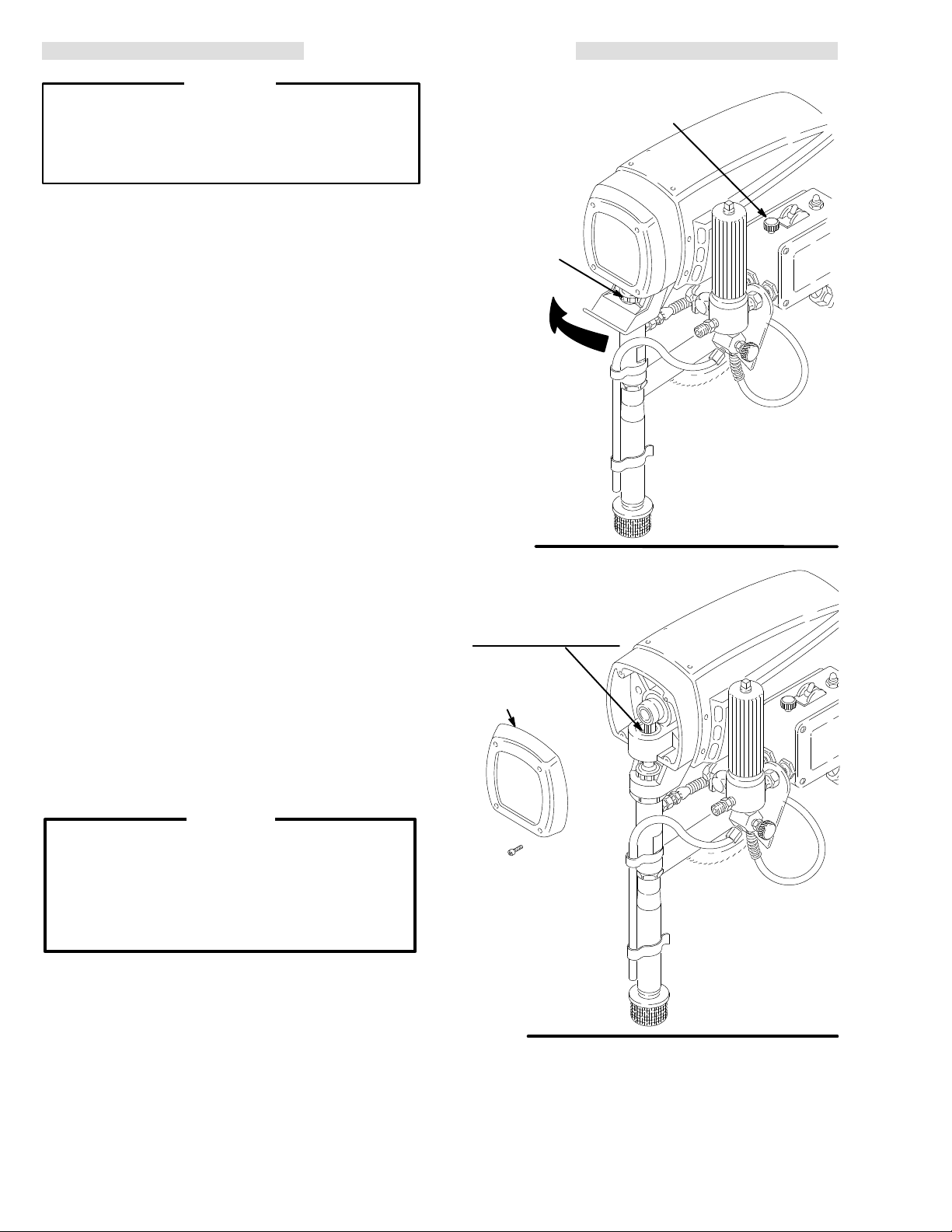
Lubricate the bearing housing after every 100
procedure.
hours of operation. First relieve pressure. Remove
the front cover. Fill the bearing housing cavity with
SAE
10 non-detergent oil. See Fig 14–2.
4. For very short shutoff periods, leave the suction
tube in the paint, relieve pressure, and clean the
spray
tip.
5. Flush
the sprayer at the end of each work day
fill
it with mineral spirits to help prevent pump corro
and freezing. See page 15.
sion
and
-
TIGHTEN
-
Fig 14-1
FILL BEARING HOUSING
CA
VITY WITH SAE
NON-DETERGENT OIL
AFTER EVER
HOURS OF OPERATION
FRONT
COVER
Y 100
01566
-
CAUTION
To prevent pump corrosion, and to reduce the
chance
trol in cold weather, never leave water or any type
of
can
of
6.
14
of fluid
freezing in the pump or pressure con
paint in the sprayer when it is not in use.
Freezing
seriously damage the sprayer or result in a loss
pressure or stalling.
Coil
the hose and hang it on the
storing
from
it, even for overnight, to help protect the hose
kinking, abrasion, coupling damage, etc.
hose rack
307–758
-
when
Fig 14-2
01567
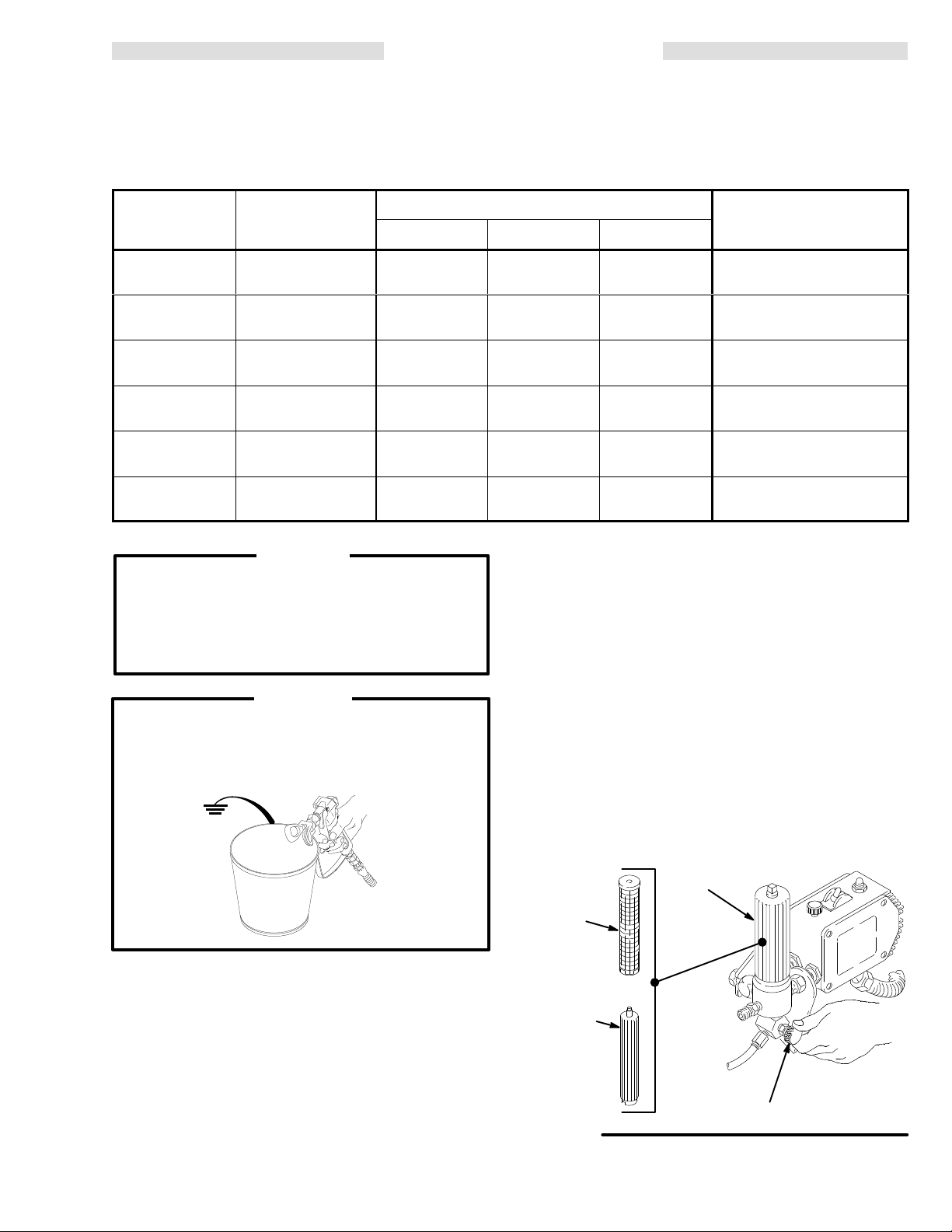
FLUSHING GUIDELINES
NOTE: Several
sprayed, or to store the sprayer
flushes are often required to thoroughly clean the system and prepare it for the next fluid to be
. Use this chart to determine the required flushing order for the fluid you are
using, and then follow the procedure below for flushing.
*Use this category for flushing a brand new sprayer and flushing after storage.
System has
this fluid in it:
Next fluid to be
sprayed.
Flushing order:
Flush 1 Flush 2 Flush 3
*Oil-based
solvent or paint
Oil-based
solvent or paint
Oil-based
solvent or paint
Water or waterbased paint
Water or waterbased paint
Water or waterbased paint
Oil-based paint –
new color
W
ater-based paint
Prepare for
storage
W
ater-based paint
– new color
Oil-based paint
Prepare for
storage
Mineral spirits
none none
Mineral spiritsWarm soapy
water
Mineral spirits
W
arm soapy
none none
Clean water
water
W
arm soapy
Clean water
water
W
arm soapy
Clean water
water
Clean water
none
Mineral spirits
Mineral spirits
Before you spray or store
sprayer:
Prime with oil-based paint
Prime with water-based
paint
Relieve pressure,
Leave drain valve open
Prime with water
Prime with oil
Relieve pressure,
Leave drain valve open
CAUTION
NEVER allow water to freeze in the pressure
control. Doing so prevents the sprayer from being
started
control.
and causes serious damage
to the pressure
Pump the water out with mineral spirits.
WARNING
To reduce the risk of static sparking and splashing
when
flushing, always remove the spray tip from the
gun
and hold a metal part of the gun firmly to the side
of
a grounded metal pail.
1. Follow
2. Turn
the illustrated
page
4. Engage the gun safety latch.
Pressure
the pressure adjusting knob fully
wise
to the minimum pressure.
Relief Procedure
counterclock
0143
on
5. Start
the sprayer
in the sprayer
until
the next fluid appears, then trigger the gun back
into
the fluid you are pumping. Circulate the
. See page 12. T
o save the fluid still
, trigger the gun into another container
fluid a couple of minutes to thoroughly clean the
system.
6. Do not run the pump dry for more than 30 seconds
to
avoid damaging the pump packings!
7. Follow
the illustrated
page
4. Engage the gun safety latch.
Pressure
Relief Procedure
8. Unscrew the filter bowl and reinstall the clean
screen. Install the bowl and hand
tighten.
FILTER
BOWL
SCREEN
FILTER
-
SUPPORT
flushing
on
3. Remove
the spray tip from the gun. Remove the
bowl and screen; see manual 307–273. Clean the
screen separately and install the bowl without the
screen
4.
Put the suction tube into a grounded metal pail with
to flush it. See Fig 15–1.
1/2 gallon of compatible solvent.
filter
Fig
15–1
PRESSURE
DRAIN
V
ALVE
01365
307–758 15
 Loading...