


3A2989G
Table of contents
 Loading...
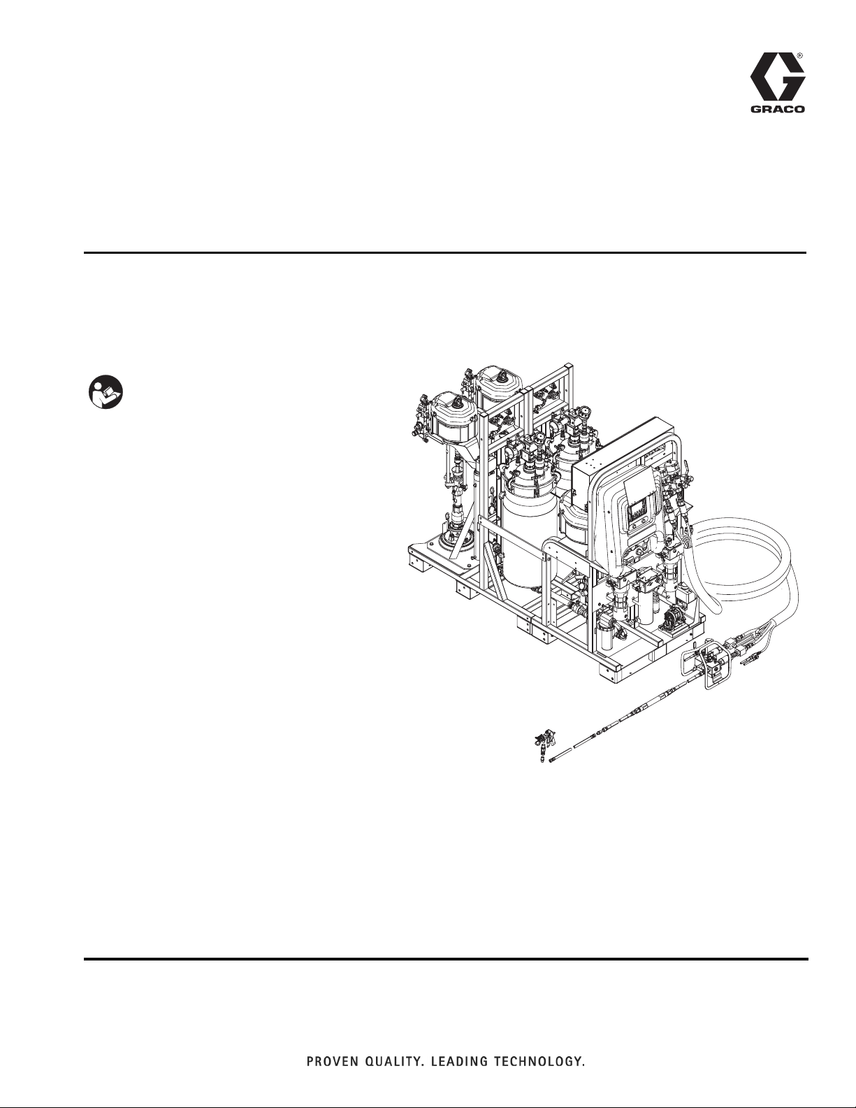
Repair - Parts
XM PFP
For spraying two-component intumescent epoxies. For professional use only.
Not for use in explosive atmospheres or hazardous locations.
Important Safety Instructions
Read all warnings and instructions in all
supplied manuals. Save all instructions.
See page 3 for model information, including
maximum working pressure and approvals.
3A2989G
EN
WLD

Contents
Models . . . . . . . . . . . . . . . . . . . . . . . . . . . . . . . . . . . 3
Related Manuals . . . . . . . . . . . . . . . . . . . . . . . . . . . 3
Warnings . . . . . . . . . . . . . . . . . . . . . . . . . . . . . . . . . 4
Keep Components A and B Separate . . . . . . . . 6
Changing Materials . . . . . . . . . . . . . . . . . . . . . . . 6
Components A and B . . . . . . . . . . . . . . . . . . . . . 6
Component Identification . . . . . . . . . . . . . . . . . . . . 6
Grounding . . . . . . . . . . . . . . . . . . . . . . . . . . . . . . . . 6
Pressure Relief Procedure . . . . . . . . . . . . . . . . . . . 7
Troubleshooting . . . . . . . . . . . . . . . . . . . . . . . . . . . 8
Repair . . . . . . . . . . . . . . . . . . . . . . . . . . . . . . . . . . . . 9
Replace Air Filter Element . . . . . . . . . . . . . . . . . 9
User Interface/Control Box . . . . . . . . . . . . . . . . 10
Junction Box . . . . . . . . . . . . . . . . . . . . . . . . . . . 15
Air Controls . . . . . . . . . . . . . . . . . . . . . . . . . . . . 17
Dosing Valve Assembly . . . . . . . . . . . . . . . . . . 19
Sensors . . . . . . . . . . . . . . . . . . . . . . . . . . . . . . . 20
Pump Assembly (System Module) . . . . . . . . . . 21
Pail Feed RAM Pump Assembly (Feed Module) 22
Solvent Pump . . . . . . . . . . . . . . . . . . . . . . . . . . 22
Heaters . . . . . . . . . . . . . . . . . . . . . . . . . . . . . . . 23
Replace Radar Level Sensor . . . . . . . . . . . . . . 24
Set Up a New Guided Radar Level Sensor . . . 25
Electrical Schematics . . . . . . . . . . . . . . . . . . . . . . 27
Simplified Electrical Schematic . . . . . . . . . . . . . 27
Parts . . . . . . . . . . . . . . . . . . . . . . . . . . . . . . . . . . . . 32
XM PFP System (262869, 24W626) . . . . . . . . . 32
Base System (262878, 24W648) Subassemblies 44
Technical Data . . . . . . . . . . . . . . . . . . . . . . . . . . . . 58
Notes . . . . . . . . . . . . . . . . . . . . . . . . . . . . . . . . . . . . 61
Graco Standard Warranty . . . . . . . . . . . . . . . . . . . 62
Graco Information . . . . . . . . . . . . . . . . . . . . . . . . 62
2 3A2989G
Models
Models
Models
Maximum Fluid
Working Pressure
Maximum Air Working
Pressure Approvals
A and B Materials:
6000 psi
(41 MPa, 414 bar)
Supply: 150 psi
262869
24W626
Flushing Fluid:
4500 psi
(31 MPa, 310 bar)
(1.0 MPa, 10.3 bar)
Max. Setpoint: 100 psi
(0.7 MPa, 7 bar)
Heating Fluid:
100 psi
(0.7 MPa, 7 bar)
Related Manuals
Manuals are available at www.graco.com. Component
manuals in English:
Manual Description
3A2776 XM PFP Setup - Operation
3A2988 XM PFP Mix Manifold Instructions - Parts
3A2799 XHF Spray Gun
Certified to CAN/CSA C22.2 No. 88
9902471
Conforms to
UL 499
Manual Description
Accessories
332073 Hot Water Flush Kit Instructions
3A2987 Air Dryer Kit Instructions
Other
313342 Dosing Valve Instructions - Parts
Heaters
®
309524
3A2954
3A2824 Viscon LT Fluid Heater Instructions - Parts
Pumps, Motors, Supply Systems
308652
311238
311762
312375
312376
312792
312794 Merkur Pump Assembly Instructions - Parts
312796 NXT Air Motor Instructions - Parts
313526 Supply Systems Operation
313527 Supply Systems Repair - Parts
312374 Air Control Instructions - Parts
Viscon
Instructions - Parts
Viscon HF High Flow, High Pressure Fluid
Heater Instructions - Parts
Husky
Pumps Instructions - Parts
NXT
Xtreme
Check-Mate® Displacement Pumps
Instructions - Parts
Check-Mate Pump Packages Instructions Parts
Merkur® Pump Repair - Parts
HP High Pressure Fluid Heater
™
205 Air-Operated Diaphragm
®
Air Motor Instructions - Parts
®
Lowers Instructions - Parts
306861 Ball Valves Instructions - Parts
307005 High Pressure Swivel Instructions - Parts
308169
407061 Simulation XM PFP Display Module
3A1244
Air Filters, Lubricators, and Kits Instructions
- Parts
Graco Control Architecture Module Programming
3A2989G 3

Warnings
Warnings
The following warnings are for the setup, use, grounding, maintenance, and repair of this equipment. The exclamation point symbol alerts you to a general warning and the hazard symbols refer to procedure-specific risks. When
these symbols appear in the body of this manual or on warning labels, refer back to these Warnings. Product-specific
hazard symbols and warnings not covered in this section may appear throughout the body of this manual where
applicable.
WARNING
WARNINGWARNINGWARNING
ELECTRIC SHOCK HAZARD
This equipment must be grounded. Improper grounding, setup, or usage of the system can cause
electric shock.
• Turn off and disconnect power at main switch before disconnecting any cables and before servicing
or installing equipment.
• Connect only to grounded power source.
• All electrical wiring must be done by a qualified electrician and comply with all local codes and
regulations.
SKIN INJECTION HAZARD
High-pressure fluid from gun, hose leaks, or ruptured components will pierce skin. This may look like just
a cut, but it is a serious injury that can result in amputation. Get immediate surgical treatment.
• Do not spray without tip guard and trigger guard installed.
• Engage trigger lock when not spraying.
• Do not point gun at anyone or at any part of the body.
• Do not put your hand over the spray tip.
• Do not stop or deflect leaks with your hand, body, glove, or rag.
•Follow the Pressure Relief Procedure when you stop spraying and before cleaning, checking, or
servicing equipment.
• Tighten all fluid connections before operating the equipment.
• Check hoses and couplings daily. Replace worn or damaged parts immediately.
FIRE AND EXPLOSION HAZARD
Flammable fumes, such as solvent and paint fumes, in work area can ignite or explode. To help prevent
fire and explosion:
• Use equipment only in well ventilated area.
• Eliminate all ignition sources; such as pilot lights, cigarettes, portable electric lamps, and plastic drop
cloths (potential static arc).
• Keep work area free of debris, including solvent, rags and gasoline.
• Do not plug or unplug power cords, or turn power or light switches on or off when flammable fumes
are present.
• Ground all equipment in the work area. See Grounding instructions.
• Use only grounded hoses.
• Hold gun firmly to side of grounded pail when triggering into pail. Do not use pail liners unless they
are antistatic or conductive.
• Stop operation immediately if static sparking occurs or you feel a shock. Do not use equipment
until you identify and correct the problem.
• Keep a working fire extinguisher in the work area.
BURN HAZARD
Equipment surfaces and fluid that’s heated can become very hot during operation. To avoid severe
burns:
• Do not touch hot fluid or equipment.
4 3A2989G

Warnings
WARNING
WARNINGWARNINGWARNING
MOVING PARTS HAZARD
Moving parts can pinch, cut or amputate fingers and other body parts.
• Keep clear of moving parts.
• Do not operate equipment with protective guards or covers removed.
• Pressurized equipment can start without warning. Before checking, moving, or servicing equipment,
follow the Pressure Relief Procedure and disconnect all power sources.
EQUIPMENT MISUSE HAZARD
Misuse can cause death or serious injury.
• Do not operate the unit when fatigued or under the influence of drugs or alcohol.
• Do not exceed the maximum working pressure or temperature rating of the lowest rated system
component. See Technical Data in all equipment manuals.
• Use fluids and solvents that are compatible with equipment wetted parts. See Technical Data in all
equipment manuals. Read fluid and solvent manufacturer’s warnings. For complete information
about your material, request MSDS from distributor or retailer.
• Do not leave the work area while equipment is energized or under pressure.
• Turn off all equipment and follow the Pressure Relief Procedure when equipment is not in use.
• Check equipment daily. Repair or replace worn or damaged parts immediately with genuine manufacturer’s replacement parts only.
• Do not alter or modify equipment. Alterations or modifications may void agency approvals and create
safety hazards.
• Make sure all equipment is rated and approved for the environment in which you are using it.
• Use equipment only for its intended purpose. Call your distributor for information.
• Route hoses and cables away from traffic areas, sharp edges, moving parts, and hot surfaces.
• Do not kink or over bend hoses or use hoses to pull equipment.
• Keep children and animals away from work area.
• Comply with all applicable safety regulations.
TOXIC FLUID OR FUMES HAZARD
Toxic fluids or fumes can cause serious injury or death if splashed in the eyes or on skin, inhaled, or
swallowed.
• Read MSDSs to know the specific hazards of the fluids you are using.
• Store hazardous fluid in approved containers, and dispose of it according to applicable guidelines.
PERSONAL PROTECTIVE EQUIPMENT
Wear appropriate protective equipment when in the work area to help prevent serious injury, including
eye injury, hearing loss, inhalation of toxic fumes, and burns. This protective equipment includes but is
not limited to:
• Protective eyewear, and hearing protection.
• Respirators, protective clothing, and gloves as recommended by the fluid and solvent manufacturer
SPLATTER HAZARD
Hot or toxic fluid can cause serious injury if splashed in the eyes or on skin. During blow off of platen,
splatter may occur.
• Use minimum air pressure when removing platen from drum.
3A2989G 5
Component Identification
Keep Components A and B Separate
Cross-contamination can result in cured material in
fluid lines which could cause serious injury or damage
equipment. To prevent cross-contamination:
• Never interchange component A and component
B wetted parts.
• Never use solvent on one side if it has been contaminated from the other side.
Changing Materials
NOTICE
Changing the material types used in your equipment
requires special attention to avoid equipment damage
and downtime.
• When changing materials, flush the equipment multiple times to ensure it is thoroughly clean.
Component Identification
See XM PFP Operation manual for component identification.
Grounding
The equipment must be grounded to reduce the risk
of static sparking and electric shock. Electric or static
sparking can cause fumes to ignite or explode.
Improper grounding can cause electric shock.
Grounding provides an escape wire for the electric
current.
Ground the electrical connection properly according to
local codes.
• Always clean any fluid inlet strainers after flushing.
• Check with your material manufacturer for chemical
compatibility.
• When changing between epoxies and urethanes or
polyureas, disassemble and clean all fluid components and change hoses. Epoxies often have
amines on the B (hardener) side. Polyureas often
have amines on the B (resin) side.
Components A and B
IMPORTANT!
Material suppliers can vary in how they refer to plural
component materials.
Be aware that in this manual:
Component A refers to resin or major volume.
Component B refers to the hardener or minor volume.
This equipment doses the B component into the A component flow. An integration hose must always be used
after the mix manifold and before the static mixer.
6 3A2989G

Pressure Relief Procedure
Pressure Relief Procedure
Follow the Pressure Relief Procedure whenever
you see this symbol.
This equipment stays pressurized until pressure is
manually relieved. To help prevent serious injury
from pressurized fluid, such as skin injection,
splashing fluid and moving parts, follow the Pressure
Relief Procedure when you stop spraying and before
cleaning, checking, or servicing the equipment.
1. Engage trigger lock.
TI19265a2
2. If the system will be shut down for more than a few
hours, perform Park Fluid Pump Rods procedure
in XM PFP Operation manual to prevent fluid hardening on the pump shaft.
NOTICE
The material may expand when air pressure is
removed. This can cause the tank to overfill and
damage the parts attached to the tank lid. To prevent overfilling the tank, never relieve air pressure
in the tank unless the tank is less than half full.
Verify tank material level on the user interface, see
Appendix A - User Interface Display section in
XM PFP Operation manual.
5. If necessary to relieve tank air pressure: close both
feed system air control ball valves and back out the
air pressure regulator. Open the brass valves on the
tank lids for full tank de-pressurization. Pressure
gauge should read 0 psi.
FEED PUMP
BYPASS
ti20127a
3. Press (Stop button).
4. Slide the feed pump air supply valve (DF) and director valve air supply valve (DA) to the OFF position.
DF
DD
DA
F
IG
. 1: Feed Pump Controls
ti20104a
DE
DC
DB
F
IG
. 2
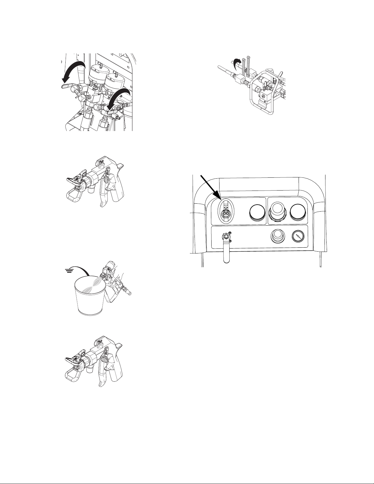
6. Open mix manifold ball valves.
ti20128a
3A2989G 7
Troubleshooting
7. Open recirculation ball valves.
WLD
8. Disengage trigger lock.
TI19265a1
9. Hold a metal part of the gun firmly to a grounded
metal pail. Trigger gun to relieve pressure in material hoses. Use a pail lid with a hole to dispense
through. Seal around hole and gun with a rag to prevent splash back.
11. Close mix manifold material ball valves.
ti20129a
12. Perform Flush Mixed Material procedure in XM
PFP Operation manual to prevent mixed material
curing in the system and to relieve pressure in the
solvent lines.
13. Close metering pump air supply ball valve.
10. Engage trigger lock.
TI1953a
TI19265a2
14. If the system will be shutdown for more than a few
hours, fill pump A and B packing nuts with throat
seal liquid (TSL
™
).
NOTE: Fluid pressure in the system is now relieved.
Troubleshooting
See XM PFP Operation manual 3A2776 for troubleshooting details.
8 3A2989G

Repair
Repair
NOTICE
Do not use air motor lift rings to lift the entire
assembly. This will damage the system. The system must be lifted from the bottom.
Follow Pressure Relief Procedure on page 7 if service
time may exceed pot life time, before servicing fluid
components, and before transporting sprayer.
Replace Air Filter Element
There are two air filters on the system: the inlet air regulator filter on the air controls and the main air inlet manifold filter. Check filters weekly and replace element as
needed.
3. Unscrew filter bowl from inlet air regulator (601d).
4. Remove and replace element.
601d
Filter Bowl
and Element
r_312359_313289_15
5. Screw filter bowl on securely.
6. Replace front and rear shrouds (19, 20) using four
nuts (21).
Main Air Inlet Manifold Filter
2. Unscrew filter bowl collar from main air inlet
filter (14).
To reduce the risk of serious injury, do not service air
filter until air line is depressurized. Removing a pressurized air filter bowl could cause serious injury.
Both Filters
1. Close main air shutoff valve on air supply line and
on system. Depressurize air line.
Control Air Regulator Filter
2. Remove four nuts (21) and then remove front and
rear shrouds (19, 20).
21
20
19
14
ti199526a1
3. Remove and replace filter element (701a). See Air
Filter (24P899), page 49.
4. Reassemble filter bowl.
ti19926a1
3A2989G 9

Repair
User Interface/Control Box
Remove Shroud and Front Panel of Control
Box
1. Close main air shutoff valve on air supply line and
on system. Depressurize air line.
2. Remove four nuts (21) and then remove front and
rear shrouds (19, 20).
21
20
19
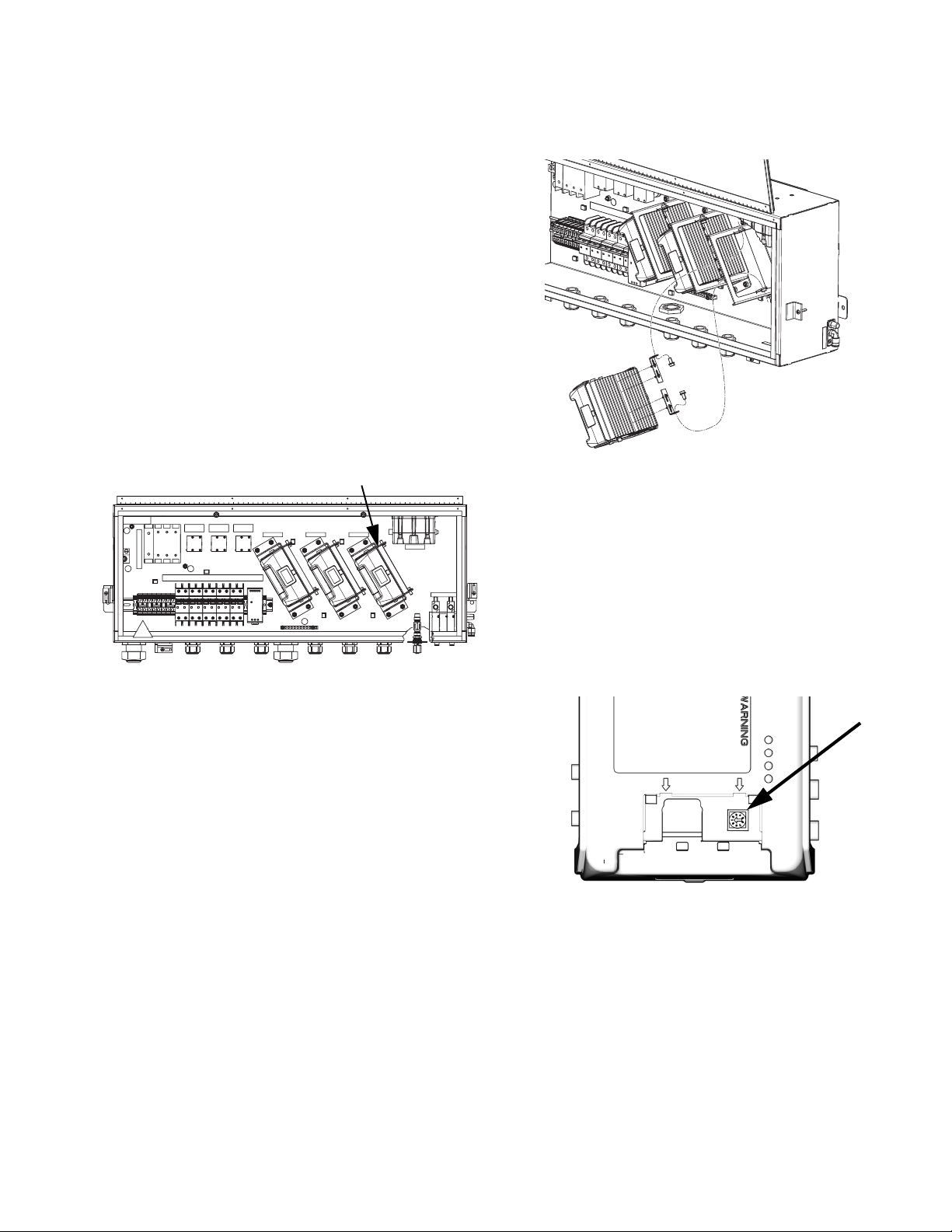
2. Disconnect solenoid cable connector (542) from the
solenoid (509a) being replaced.
3. Remove two screws (509b) from the solenoid being
replaced then remove solenoid (509a). See F
IG
. 4.
509b
r_xm1a00_312359_313289_9_3
509a
FIG. 4
4. Use screws (509b) to install new solenoid (509a).
ti19926a1
3. Disconnect power.
4. Remove four nuts (17); leave two nuts on left side of
panel tight. Open front panel of control box (16).
See F
IG
. 3.
17
16
ti20158b1
IG
. 3
F
5. Reconnect solenoid cable connectors (542). See
Control Box (255771) on page 47.
NOTE:
From left to right, solenoid functions are as follows:
• Dosing valve A (DVA) (normally open)
• Dosing valve B (DVB) (normally open)
• Pump A (PA) (normally closed)
• Pump B (PA) (normally closed)
DVA
DVB
PA
PB
r_xm1a00_312359_313289_9_3
Replace Single Solenoid Module
1. Remove Shroud and Front Panel of Control Box,
see page 10.
10 3A2989G
Repair
Update USB Module Software
1. Remove four nuts (21) and then remove front and
rear shrouds (19, 20).
21
20
19
ti19926a1
2. Use software token 16P644. See Graco Control
Architecture
instructions.
NOTE: Upgrade all modules in the system to the
software version on the token, even if you are
replacing only one or two modules. Different software versions may not be compatible.
All data in the module may be reset to factory
default settings. Record all settings and user preferences before the upgrade, for ease of restoring
them following the upgrade.
™
Module Programming manual for
Replace USB Module
1. Remove Shroud and Front Panel of Control Box,
see page 10.
2. Disconnect CAN cables and USB cable from USB
module (519).
3. Remove two mounting screws from USB module
and remove module from base.
r_312359_313289_23a
519
4. Follow steps in reverse order to install new USB
module.
5. Load software. See Update USB Module Soft-
ware.
The latest software version for each system can be
found at Tech Support at www.graco.com.
3A2989G 11
Repair
Update Fluid Control Module (FCM)
Software
1. Remove four nuts (21) and then remove front and
rear shrouds (19, 20).
21
20
19
ti19926a1
2. Use software token 16P644. See Graco Control
Architecture
instructions.
NOTE: Upgrade all modules in the system to the
software version on the token, even if you are
replacing only one or two modules. Different software versions may not be compatible.
All data in the module may be reset to factory
default settings. Record all settings and user preferences before the upgrade, for ease of restoring
them following the upgrade.
™
Module Programming manual for
3. Loosen four mounting screws (535).
r_312359_313289_26
518
535
535
4. Slide FCM up and out of keyhole slots.
5. Follow steps in reverse order to install new FCM.
6. Load software. See Update Fluid Control Module
(FCM) Software.
7. Most of the system configuration is stored in the
FCM. Use the display to change the configuration to
the values in the old FCM. See XM PFP operation
manual for instructions.
Replace Alarm
1. Remove Shroud and Front Panel of Control Box,
see page 10.
2. Disconnect alarm wires from alarm (517).
The latest software version for each system can be
found at Tech Support at www.graco.com.
Replace Fluid Control Module (FCM)
NOTE:
The USB module does not need to be removed prior to
replacing the FCM.
1. Remove Shroud and Front Panel of Control Box,
see page 10.
2. Remove all cables from FCM (518). Take note of
cable locations.
3. Unscrew alarm (517) and replace.
r_312359_313289_22
517
4. Screw in new alarm. Reconnect alarm wires.
5. Reinstall front panel of control box and reinstall
shrouds.
12 3A2989G
Repair
Display
Upgrade Software
NOTICE
To avoid damaging circuit board, wear a grounding
strap.
Use software token 16P644. See Graco Control Architecture
NOTE: Upgrade all modules in the system to the
software version on the token, even if you are
replacing only one or two modules. Different software versions may not be compatible.
All data in the module may be reset to factory
default settings. Record all settings and user preferences before the upgrade, for ease of restoring
them following the upgrade.
The latest software version for each system can be
found at Tech Support at www.graco.com.
™
Module Programming manual for instructions.
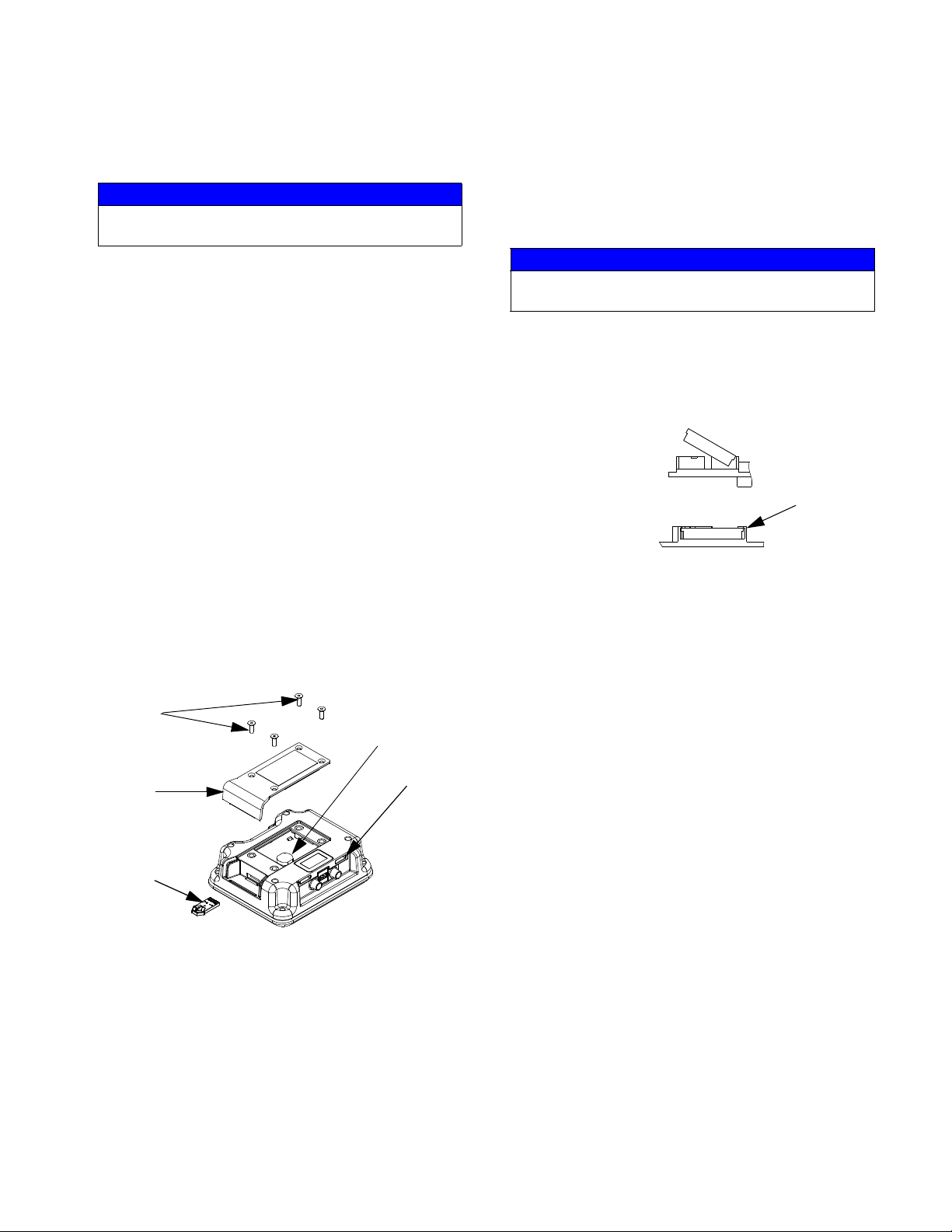
6. Turn power off.
7. Remove token (T).
8. Use screws (512) to install access cover (511).
Replace Display Battery
NOTICE
To avoid damaging circuit board, wear a grounding
strap.
1. Perform steps 1-2 in the Upgrade Software section
on page 13.
2. Use a flat head screwdriver to pry out old battery.
Remove Old Battery
Connector
Insert New Battery
r_xm1a00_312359_313289_9_8a
Tabs
1. Remove Shroud and Front Panel of Control Box,
see page 10.
2. Remove four screws (512) then remove access
cover (511).
512
Battery
L
511
T
r_xm1a00_312359_313289_2a
3. Insert and press token (T) firmly into slot.
NOTE:
There is no preferred orientation of token.
3. Replace with new battery. Ensure battery fits under
connector tabs before snapping other end in place.
NOTE:
Use only Panasonic CR2032 batteries for replacement.
4. Use screws (512) to install access cover (511).
4. Turn power on.
5. The red indicator light (L) will flash until new software is completely loaded.
3A2989G 13
Repair
Replace Display
NOTE: Order display kit 257484 for replacement.
NOTICE
To avoid damaging circuit board, wear a grounding
strap.
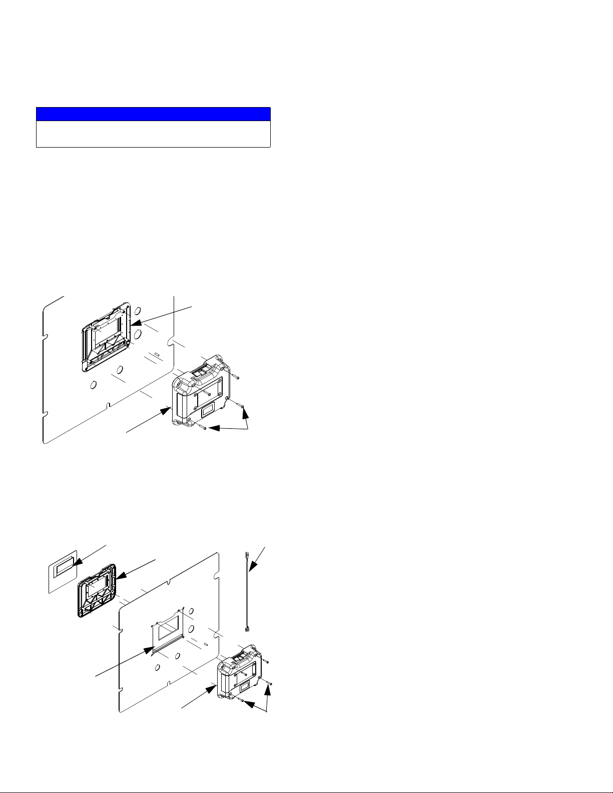
1. Remove Control Box Shrouds, see page 17.
2. Disconnect CAN cable from display module.
3. Remove four screws (505) from rear display panel
(506) while holding front display panel (507) in
place.
NOTE:
To ease removal use clear tape to hold front display
panel (507) in place.
507
6. Discard old display assembly.
7. Place new front display panel (507) and
gasket (513) on front panel of control box (16).
NOTE:
To ease installation use clear tape to hold front display
panel in place.
8. Carefully connect display cables and key switch
cable to new circuit board.
9. Install new rear display panel (506) and secure with
four screws (505). Ensure key switch cable protrudes from opening in top of display module.
10. Install access cover and screws. Apply warning
label to access cover.
11. Reconnect CAN cable to display module.
12. Reconnect power.
13. Load software. See Upgrade Software, page 13.
14. Replace shroud.
r_312359_313289_24a
15. Configure system settings as they were set on old
display. See XM PFP Operation manual for instructions.
506
505
4. Remove rear display panel (505) and disconnect
display cable and key switch cable (539) from circuit
board.
5. Remove front display panel (507) and gasket (513).
Display Cable
539
507
513
r_xm1a00_312359_313289_25a
506
505
Replace Front Panel
See Replace Display, page 14, for instructions.
14 3A2989G
Repair
Junction Box
Update High Power Temperature Control
Module (HPTCM, ref. 404) Software
NOTE: Upgrade all modules in the system to the
software version on the token, even if you are
replacing only one or two modules. Different software versions may not be compatible.
All data in the module may be reset to factory
default settings. Record all settings and user preferences before the upgrade, for ease of restoring
them following the upgrade.
The latest software version for each system can be
found at Tech Support at www.graco.com.
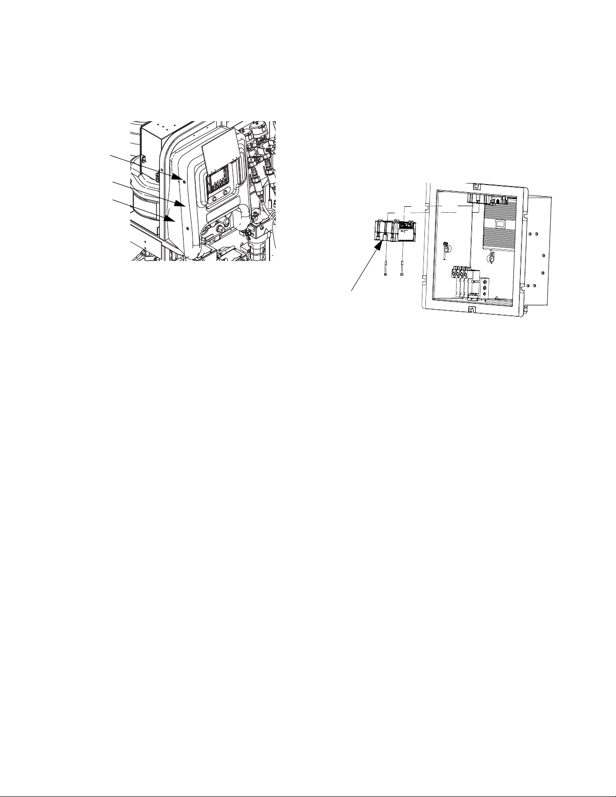
1. Open junction box.
404
B HOSE A
Replace High Power Temperature Control
Module (HPTCM, ref. 404)
ti21595a
1. Turn system main power switch OFF.
2. Open junction box.
3. Unplug all connections on the HPTCM.
ti20155a
2. Use software token 16P644. See Graco Control
Architecture
™
Module Programming manual for
instructions.
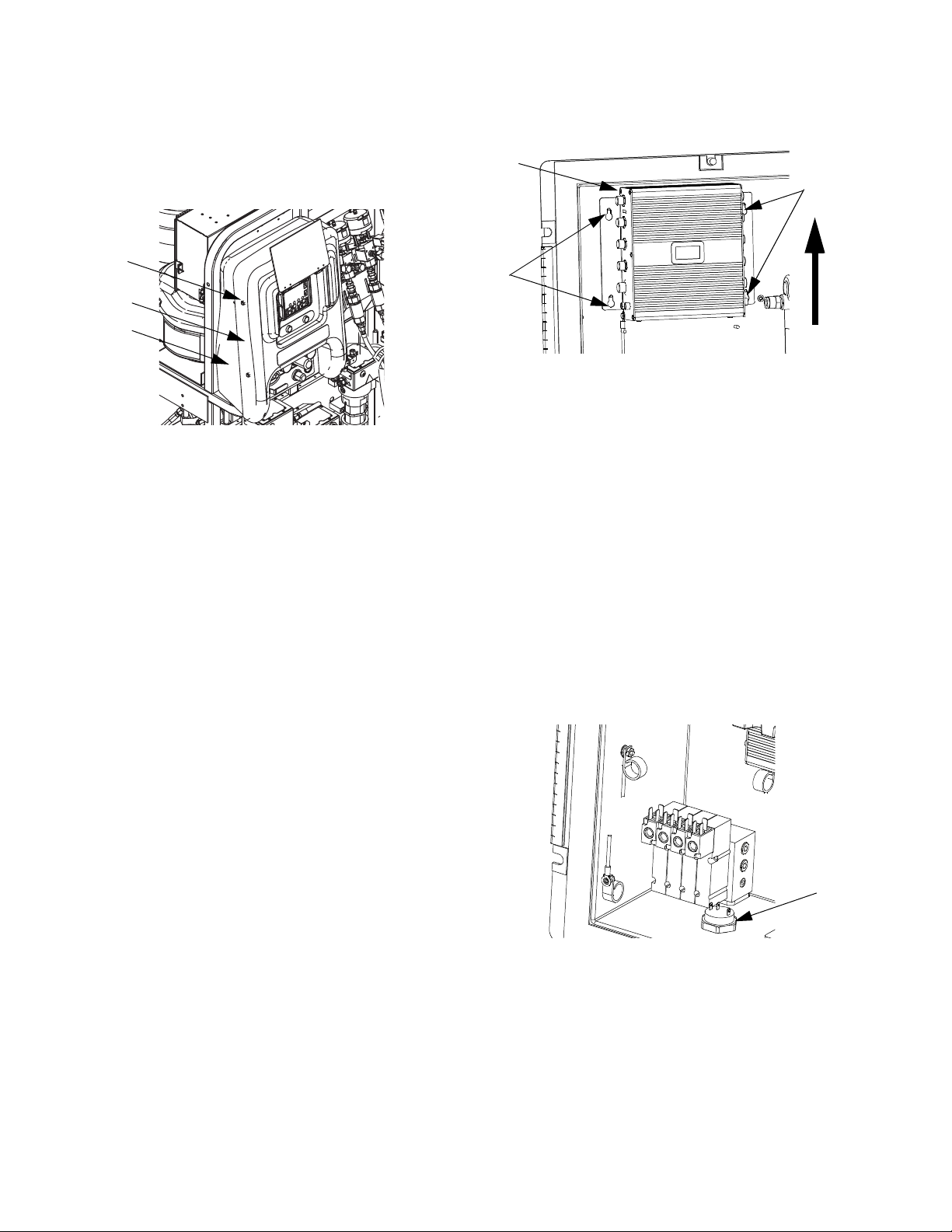
4. Remove screws securing HPTCM then remove
HPTCM.
5. Remove access door on new HPTCM. Set rotary
switches to the same number as the old module.
B module = 1. Hose module = 2. A module = 0.
ti12360a
6. Use screws to install HPTCM.
7. Reattach HPTCM connections.
8. Close junction box.
3A2989G 15
Repair
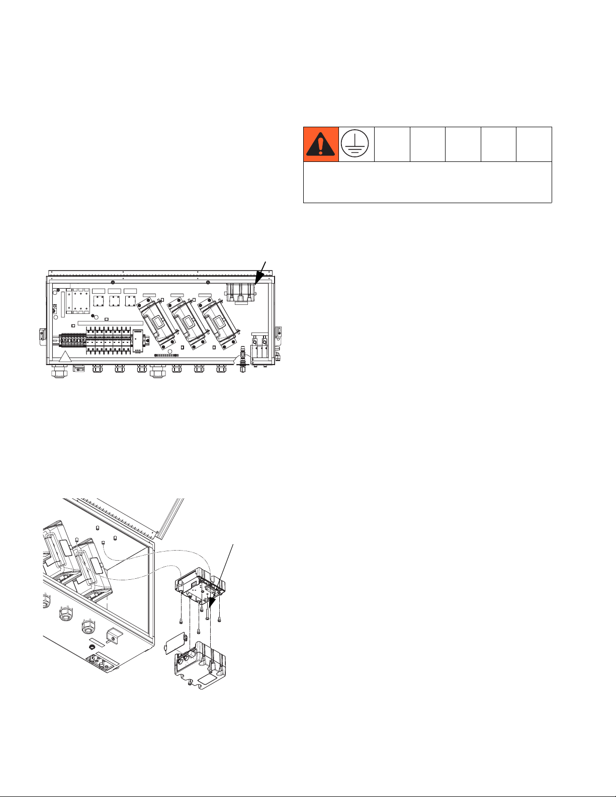
Update Fluid Control Module Cube (FCM3,
ref. 415) Software
NOTE: Upgrade all modules in the system to the
software version on the token, even if you are
replacing only one or two modules. Different software versions may not be compatible.
All data in the module may be reset to factory
default settings. Record all settings and user preferences before the upgrade, for ease of restoring
them following the upgrade.
The latest software version for each system can be
found at Tech Support at www.graco.com.
415
B HOSE A
3. Unplug all connections on the FCM3.
4. Remove two screws securing FCM3 then remove
FCM3.
Center ground screw in the Fluid Control Module
Cube must be used to avoid serious injury due to
electric shock.
5. Use screws to install FCM3.
6. Reattach FCM3 connections.
7. Perform Update Fluid Control Module Cube
(FCM3, ref. 415) Software on page 16.
8. Close junction box.
ti20155a
1. Open junction box.
2. Use software token 16P644. See Graco Control
Architecture
™
Module Programming manual for
instructions.
Replace Fluid Control Module Cube (FCM3,
ref. 415)
Ground screw
ti21594a
1. Turn system main power switch OFF.
2. Open junction box.
16 3A2989G

Repair
Air Controls
Remove Control Box Shrouds
1. Close main air shutoff valve on air supply line and
on system. Depressurize air line.
2. Remove four nuts (21) and then remove front and
rear shrouds (19, 20).
21
20
19
ti19926a1
Remove Air Control Assembly
1. Remove Control Box Shrouds.
2. Disconnect air motor air lines and system air line.
3. Remove four nuts (17) from front of air controls (18).
See page 36.
4. Pull out assembly.
5. Follow steps in reverse order to reinstall air control
assembly.
8. Follow steps in reverse order to reassemble.
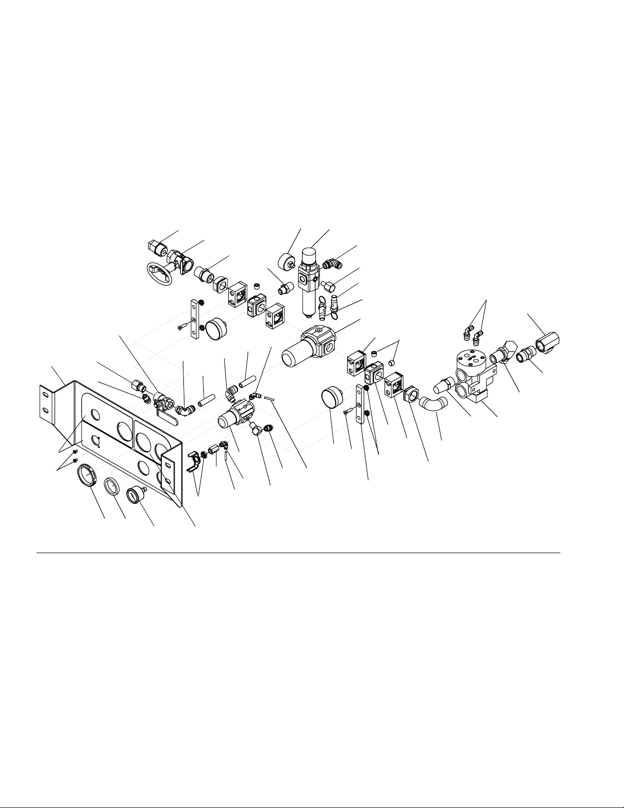
Replace Solvent Air Regulator
1. Remove Control Box Shrouds.
2. Disconnect air motor air lines and system air line.
3. Remove four nuts (17) from front of air controls (18).
See page 36.
4. Pull out assembly.
5. Remove regulator nut (631), and disconnect air
lines (632, 633) running to regulator (625). See F
5 on page 18.
6. Remove regulator assembly and replace with new.
See part number shown in the System Air Con-
trols Module (255761) section beginning on
page 44.
7. Follow steps in reverse order to reassemble.
IG
Replace System Air Regulator
1. Remove Control Box Shrouds.
2. Disconnect air motor air lines and system air line.
3. Remove four nuts (17) from front of air controls (18).
See page 36.
4. Pull out assembly.
5. Remove regulator nut (601h) and disconnect system air line.
.
Replace Solvent Pump Air Ball Valve
1. Remove Control Box Shrouds.
2. Disconnect air motor air lines and system air line.
3. Remove four nuts (17) from front of air controls (18).
See page 36.
4. Pull out assembly.
5. Remove two nuts (630) from front of air control
bracket (619). See F
6. Disconnect air line (632) running to ball valve
assembly (626).
7. Replace with new ball valve assembly. See part
number shown in the System Air Controls Module
(255761) section beginning on page 44.
3A2989G 17
IG
. 5 on page 18.
6. Remove screws from quick clamps and open
clamps (601f) at hinge.
7. Remove regulator assembly (601c) and replace with
new. See part number shown in the System Air
Controls Module (255761) section beginning on
page 44.
8. Follow steps in reverse order to reassemble.
Replace Solenoid Inlet Air Regulator
1. Remove Control Box Shrouds.
2. Disconnect air motor air lines and system air line.
3. Remove four nuts (17) from front of air controls (18).
See page 36.
4. Pull out assembly.
Repair
5. Disconnect air line.
6. Remove gauge (606) from block (601e).
7. Remove screws from quick clamps (601f) holding
air regulator assembly (601c) in place.
8. Open clamps (601f) at hinge and pull apart from
block (601e).
617
607
613
603
626
629
632
619
638
636
637
632
635
9. Remove regulator assembly (601d) and replace
with new. See part number shown in the System
Air Controls Module (255761) section beginning
on page 44.
10. Follow steps in reverse order to reassemble.
11. Set new air pressure regulator to at least 80-85 psi
(0.55-0.58 MPa, 5.5-5.8 bar).
616
644
608
610
611
Ref. 27
645
642
612
609
615
617
613
618
630
F
IG
. 5
640
631
627
627
618
628
633
625
629
634
635
633
606
621
620
622
643
642
641
604
646
647
18 3A2989G
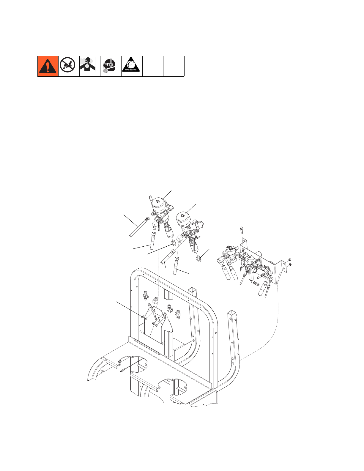
Dosing Valve Assembly
Repair
1. Follow Pressure Relief Procedure, page 7.
2. Disconnect all fluid lines from dosing valves (28 or
IG
29). See F
3. Remove two bolts (31) securing dosing valve to
bracket.
4. Unscrew dosing valve nipple fitting (36 or 37) from
dosing valve outlet.
5. Disconnect pressure sensor (831) from dosing
valve. See page 50.
. 6.
29
55
85
36
6. Remove dosing valves.
7. See Ratio Control Valve Assemblies on page 50
for disassembly illustration.
8. Follow steps in reverse order to reassemble dosing
valve assembly. See Ratio Control Valve Assem-
blies on page 50 for assembly illustration and specifications.
28
37
FIG. 6
31
55
54
3A2989G 19
Loading...