


 Loading...
Graco Inc. 246639, 246752, 246753, 246365, 246760 Repair - Parts
...Repair - Parts
309813H
Air Powered, Heated, Plural Component
Proportioners
For spraying polyurethane foam and polyurea coatings.
Not for use in explosive atmospheres.
Important Safety Instructions
Read all warnings and instructions in this manual.
Save these instructions.
For model information, see page 3.
TI3699b
Manual Conventions
Contents
Manual Conventions . . . . . . . . . . . . . . . . . . . . . . . . 2
Models . . . . . . . . . . . . . . . . . . . . . . . . . . . . . . . . . . . 3
Air Powered Reactors . . . . . . . . . . . . . . . . . . . . . 3
Supplied Manuals . . . . . . . . . . . . . . . . . . . . . . . . . . 4
Related Manuals . . . . . . . . . . . . . . . . . . . . . . . . . . . 5
Warning . . . . . . . . . . . . . . . . . . . . . . . . . . . . . . . . . . . 6
Before Beginning Repair . . . . . . . . . . . . . . . . . . . . 8
Flushing . . . . . . . . . . . . . . . . . . . . . . . . . . . . . . . . . . 8
Pressure Relief Procedure . . . . . . . . . . . . . . . . . . . 9
Temperature Control Diagnostic Codes . . . . . . . 10
E01: High fluid temperature . . . . . . . . . . . . . . . 10
E02: High hose current . . . . . . . . . . . . . . . . . . . 10
E03: No hose current . . . . . . . . . . . . . . . . . . . . 11
E04: FTS or thermocouple not connected . . . . 11
E05: Board overtemperature . . . . . . . . . . . . . . . 11
Troubleshooting . . . . . . . . . . . . . . . . . . . . . . . . . . . 12
Repair . . . . . . . . . . . . . . . . . . . . . . . . . . . . . . . . . . . 15
Proportioning Pump . . . . . . . . . . . . . . . . . . . . . . 15
Circuit Breaker Module . . . . . . . . . . . . . . . . . . . 16
Temperature Control Board . . . . . . . . . . . . . . . . 18
Heater . . . . . . . . . . . . . . . . . . . . . . . . . . . . . . . . 20
Heated Hose . . . . . . . . . . . . . . . . . . . . . . . . . . . 22
Fluid Temperature Sensor (FTS) . . . . . . . . . . . . 23
Display Module . . . . . . . . . . . . . . . . . . . . . . . . . 29
Parts . . . . . . . . . . . . . . . . . . . . . . . . . . . . . . . . . . . . 32
Technical Data . . . . . . . . . . . . . . . . . . . . . . . . . . . . 49
Graco Standard Warranty . . . . . . . . . . . . . . . . . . . 50
Graco Information . . . . . . . . . . . . . . . . . . . . . . . . . 50
Manual Conventions
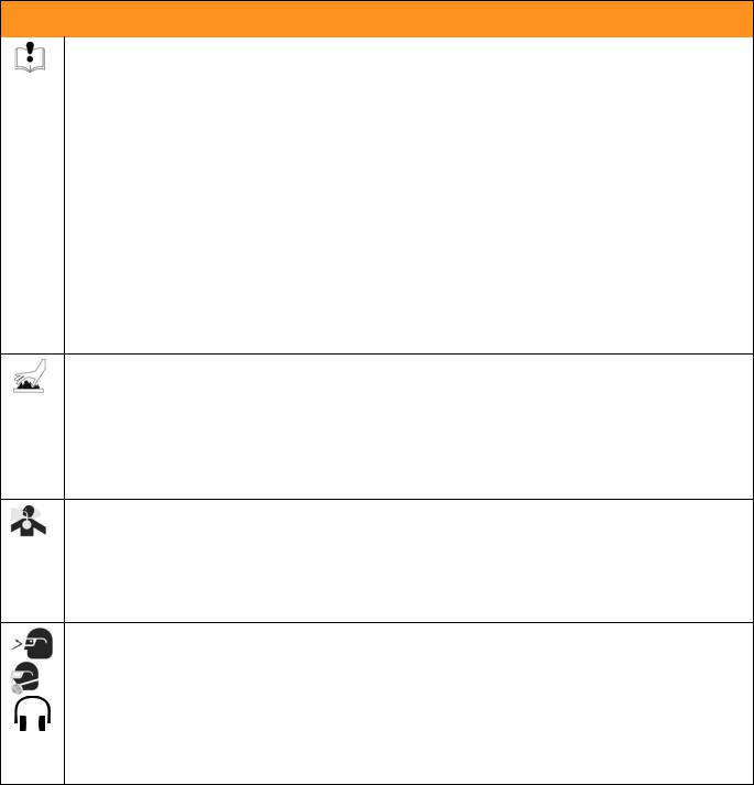
Warning
WARNING
A warning alerts you to possible serious injury or death if you do not follow instructions.
Symbols, such as fluid injection (shown), alert you to a specific hazard and direct you to read the indicated hazard warnings on pages 6-7.
Caution
CAUTION
A caution alerts you to possible equipment damage or destruction if you do not follow instructions.
Note
 A note indicates additional helpful information.
2 |
309813H |
Models
Models
Air Powered Reactors
A-XP SERIES
|
|
|
Full |
|
|
Flow |
|
|
|
|
|
Load |
|
Heater |
gpm |
Output per |
Maximum Fluid |
Part No., |
|
Voltage |
Peak |
System |
Watts |
(lpm) at |
Cycle (A + B) |
Working Pressure |
Series |
Model |
(phase) |
Amps* |
Watts** |
(no hose) |
78 cpm |
gal. (liter) |
psi (MPa, bar) |
|
|
|
|
|
|
|
|
|
246639, B |
A-XP2 |
230V (1) |
62 |
14,540 |
10,200 |
1 (3.8) |
.0193 (.073) |
3000 (20.7, 207) |
246752, B |
A-XP2 |
230V (3) |
40 |
14,540 |
10,200 |
1 (3.8) |
.0193 (.073) |
3000 (20.7, 207) |
246753, B |
A-XP2 |
380V (3) |
22 |
14,540 |
10,200 |
1 (3.8) |
.0193 (.073) |
3000 (20.7, 207) |
Heat Packages (do not include proportioner)
|
|
|
Full |
|
|
|
|
|
|
Load |
|
Heater |
Maximum Fluid |
Part No., |
|
Voltage |
Peak |
System |
Watts |
Working Pressures |
Series |
Model |
(phase) |
Amps* |
Watts** |
(no hose) |
psi (MPa, bar) |
|
|
|
|
|
|
|
246365, B |
HT-6.0 |
230V (1) |
44 |
10,340 |
6,000 |
3500 (24.1, 241) |
246760, B |
HT-6.0 |
230V (3) |
27 |
10,340 |
6,000 |
3500 (24.1, 241) |
246761, B |
HT-6.0 |
380V (3) |
18 |
10,340 |
6,000 |
3500 (24.1, 241) |
246607, B |
HT-10.2 |
230V (1) |
62 |
14,540 |
10,200 |
3500 (24.1, 241) |
246762, B |
HT-10.2 |
230V (3) |
40 |
14,540 |
10,200 |
3500 (24.1, 241) |
246763, B |
HT-10.2 |
380V (3) |
22 |
14,540 |
10,200 |
3500 (24.1, 241) |
246364, B |
HT-15.3 |
230V (1) |
84 |
19,640 |
15,300 |
3500 (24.1, 241) |
246764, B |
HT-15.3 |
230V (3) |
57 |
19,640 |
15,300 |
3500 (24.1, 241) |
246765, B |
HT-15.3 |
380V (3) |
33 |
19,640 |
15,300 |
3500 (24.1, 241) |
*Full load amps with all devices operating at maximum capabilities. Fuse requirements at various flow rates and mix chamber sizes may be less.
**Total system watts for all units, using 310 ft (94.6 m) hose.
309813H |
3 |

Supplied Manuals
Supplied Manuals
The following manuals are shipped with the Reactor™. Refer to them for detailed equipment information.
Order Part No. 15B535 for a compact disk of Reactor manuals translated in several languages.
Air and Hydraulic Reactors
Part No. Description
309812 Air and Hydraulic Reactors, Operation Manual (English)
Proportioning Pumps
Part No. |
Description |
|
|
308224 |
President® Pump Repair-Parts Manual (English) |
Motors |
|
Part No. |
Description |
|
|
306982 |
President® Air Motor Repair-Parts Manual (English) |
Displacement Pumps
Part No. Description
307430 Displacement Pumps Repair-Parts Manual (English)
Reactor Electrical Diagrams (one of following included)
Part No. Description
309854 Electrical Diagrams, 230V 1 phase
309855 Electrical Diagrams, 230V 3 phase
309576 Electrical Diagrams, 380V 3 phase
Air Regulators (air powered units only)
Part No. Description
308168 Instruction-Parts Manual (English)
4 |
309813H |

Related Manuals
Related Manuals
The following manuals are for accessories used with the Reactor™.
Order Part No. 15B535 for a compact disk of Reactor manuals translated in several languages.
Order Part No. 15B381 for a compact disk of Fusion manual translated in several languages.
Hydraulic Power Supply
Part No. Description
307550 Instruction-Parts Manual (English)
Feed Pump Kits
Part No. Description
309815 Instruction-Parts Manual (English)
Air Supply Kit
Part No. Description
309827 Instruction-Parts Manual (English) for Feed Pump Air Supply Kit
Circulation and Return Tube Kits
Part No. Description
309852 Instruction-Parts Manual (English)
Heated Hose
Part No. Description
309572 Instruction-Parts Manual (English)
Fusion Air Purge Spray Gun
Part No. Description
309550 Instruction-Parts Manual (English)
Fusion Mechanical Purge Spray Gun
Part No. Description
309856 Instruction-Parts Manual (English)
Circulation Kit
Part No. Description
309818 Instruction-Parts Manual (English)
Data Reporting Kit
Part No. Description
309814 Instruction-Parts Manual (English)
309813H |
5 |

Warning
 WARNING
SKIN INJECTION HAZARD
High-pressure fluid from gun, hose leaks, or ruptured components will pierce skin. This may look like just a cut, but it is a serious injury that can result in amputation. Get immediate surgical treatment.
•Do not point the gun at anyone or at any part of the body.
•Do not put your hand or fingers over the gun fluid nozzle.
•Do not stop or deflect leaks with your hand, body, glove, or rag.
•Do not “blow back” fluid; this is not an air spray system.
•Follow Pressure Relief Procedure, page 9, when you stop spraying and before cleaning, checking, or servicing equipment.
•Use lowest possible pressure when flushing, priming, or troubleshooting.
•Engage spray gun piston safety lock when not spraying.
•Tighten all fluid connections before operating the equipment.
•Check hoses, tubes, and couplings daily. Replace worn or damaged parts immediately. High pressure hose cannot be recoupled; replace the entire hose.
FIRE, EXPLOSION, AND ELECTRIC SHOCK HAZARD
Solvent and fumes in work area can ignite or explode. High voltage components can cause electric shock. To help prevent fire, explosion, and electric shock:
•Shut off main power switch and wait 5 minutes before opening Reactor cabinet door.
•All electrical wiring must be done by trained and qualified personnel and comply with all local codes.
•Ground equipment and conductive objects. See Grounding in the Operation manual.
•Use equipment only in well ventilated area.
•Eliminate all ignition sources, such as pilot lights, cigarettes and plastic drop cloths (potential static arc).
•Do not plug or unplug power cords or turn lights on or off when flammable fumes are present.
•Keep the work area free of debris, including solvent, rags, and gasoline.
•Hold gun firmly to side of grounded pail when triggering into pail.
•Use only grounded hoses.
•If there is static sparking or you feel a shock, stop operation immediately. Do not use equipment until you identify and correct the problem.
•To avoid chemical reaction and explosion, do not use 1,1,1-trichloroethane, methylene chloride, other halogenated hydrocarbon solvents or fluids containing such solvents in pressurized aluminum equipment.
6 |
309813H |
Warning
 WARNING
EQUIPMENT MISUSE HAZARD
Misuse can cause serious injury or death.
•For professional use only.
•Use equipment only for its intended purpose. Call your Graco distributor for information.
•Read manuals, warnings, tags, and labels before operating equipment. Follow instructions.
•Check equipment daily. Repair or replace worn or damaged parts immediately.
•Do not alter or modify equipment. Use only Graco parts and accessories.
•Do not exceed the maximum working pressure or temperature rating of the lowest rated system component. See Technical Data in all equipment manuals.
•Use fluids and solvents that are compatible with equipment wetted parts. See Technical Data in all equipment manuals. Read fluid and solvent manufacturer’s warnings.
•Route hoses and cables away from traffic areas, sharp edges, moving parts, and hot surfaces.
•Do not use hoses to pull equipment.
•Comply with all applicable safety regulations.
BURN HAZARD
This equipment is used with heated fluid, which can cause equipment surfaces to become very hot. To avoid severe burns:
•Do not touch hot fluid or equipment.
•Allow equipment to cool completely before touching it.
•Wear gloves if fluid temperature exceeds 110°F (43°C).
TOXIC FLUID OR FUMES HAZARD
Toxic fluids or fumes can cause serious injury or death if splashed in the eyes or on skin, inhaled, or swallowed.
•Read Material Safety Data Sheet (MSDS) to know the specific hazards of the fluids you are using.
•Store hazardous fluid in approved containers, and dispose of it according to applicable guidelines.
PERSONAL PROTECTIVE EQUIPMENT
You must wear proper protective equipment when operating, servicing, or when in the operating area of the equipment to help protect you from serious injury, including eye injury; inhalation of toxic fumes; and hearing loss. This equipment includes but is not limited to:
•Protective eyewear.
•Gloves, clothing, and respirator as recommended by the fluid and solvent manufacturer.
•Hearing protection.
309813H |
7 |

Before Beginning Repair
Before Beginning
Repair
WARNING
Repairing this equipment requires access to parts which may cause electric shock or other serious injury if work is not performed properly. Have a qualified electrician connect power and ground to main power switch terminals, see the Operation manual. Be sure to shut off all power to the equipment before repairing.
1. Flush if necessary, see right.
2. Trigger gun to park pumps at bottom of stroke.
3. Fill wet-cups. See operation manual.
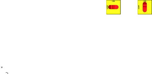
4. Turn main power OFF |
. |
5. Close red-handled valve to shut off power to
motor.
6. Relieve pressure, page 9.
Flushing
 WARNING
Read warnings, page 6. Flush equipment only in a well-ventilated area. Do not spray flammable fluids. Do not turn on heaters while flushing with flammable solvents.
•Flush out old fluid with new fluid, or flush out old fluid with a compatible solvent before introducing new fluid.
•Use the lowest possible pressure when flushing.
•All fluid components are compatible with common solvents. Use only moisture-free solvents.
•To flush feed hoses, pumps, and heaters separately from heated hoses, set PRESSURE RELIEF/SPRAY valves (SA, SB) to PRESSURE RELIEF.
SA
SB
TI3593a
•To flush entire system, circulate through gun fluid manifold (with manifold removed from gun).
•Always leave some type of fluid in system. Do not use water.
8 |
309813H |

Pressure Relief
Procedure
1.Relieve pressure in gun and perform gun shutdown procedure. See gun manual.
2.Verify gun fluid manifold valves A and B are closed.
TI2421A
3.Shut off feed pumps and agitator, if used.
4.Check that red-handled valve is closed, to shut off power to motor.
5.Turn PRESSURE RELIEF/SPRAY valves (SA, SB) to PRESSURE RELIEF. Route fluid to waste containers or supply tanks. Ensure gauges drop to 0.
SA 
SB
TI3593a
Pressure Relief Procedure
6. Engage gun piston safety lock.
TI2409A
7.Disconnect gun air line and remove gun fluid manifold.
TI2543A
 Pump throat seals work best under pressure. Close fluid inlet valves (VA, VB) when Reactor is depressurized, to prevent drum head pressure from leaking past pump piston seals.
8. Close fluid inlet valves (VA, VB).
VA
VB |
TI3698b |
309813H |
9 |
Temperature Control Diagnostic Codes
Temperature Control Diagnostic Codes
Temperature control diagnostic codes E01 through E05 |
These alarms turn off heat. Turn main power OFF |
||||
appear on temperature display. |
|
|
|
|
|
|
|
|
then ON |
to clear. |
|
|
|
|
|
|
|
Code |
Code Name |
Alarm Zone |
Corrective |
|
|
No. |
|
|
Action page |
|
|
|
|
|
|
|
|
|
|
|
|
|
|
01 |
High fluid temperature |
Individual |
10 |
|
|
|
|
|
|
|
|
02 |
High hose current |
Hose only |
10 |
|
|
|
|
|
|
|
|
03 |
No hose current with hose heater on |
Hose only |
11 |
|
|
|
|
|
|
|
|
04 |
FTS or thermocouple not connected |
Individual |
11 |
|
|
|
|
|
|
|
|
05 |
Board overtemperature |
All |
11 |
|
|
|
|
|
|
|
|
 For hose zone only, if FTS is disconnected at startup, display will show hose current 0A.
E01: High fluid temperature |
E02: High hose current |
a.Check connections between temperature control board and heater overtemperature switches, page 22.
b.Check temperature sensors, page 21.
c.Check temperature sensor is contacting heater element, page 21.
a.Check tap connection at transformer, see operation manual.
b.Check hose connections for electrical short, page 22.
c.Move to lower hose length on transformer.
d.Replace temperature control board, page 18.
10 |
309813H |
E03: No hose current
Do steps in order. Do not skip any step.
a.Check hose connectors for broken electrical connection, page 22.
b.Test hose continuity, page 25.
c.Test transformer wire harness continuity, page 25.
d.Check 50A (806) and 20A (817A) circuit breakers, page 16.
e.Test current sensor continuity, page 25.
f.Do In-Rush Current Limiter Check (380V only), page 27
g.Do Transformer Primary Check, page 27.
h.Do Transformer Secondary Check, page 27.
E04: FTS or thermocouple not connected
a.Check FTS operation by connecting directly to Reactor.
b.Check cable connections between all hose lengths.
c.Check temperature sensor connection at J1 on temperature control board, page 18.
d.Check thermocouple with ohmmeter, page 23.
Temperature Control Diagnostic Codes
e.Use manual current control mode; see operation manual.
E05: Board overtemperature
a.Check fan operation.
b.Check electrical cabinet door is properly installed.
c.Check for obstructions blocking cooling holes in bottom of Reactor.
d.Ambient temperature too high. Reduce gun mix chamber size, or move Reactor to a cooler location.
309813H |
11 |

Troubleshooting
Troubleshooting
PROBLEM |
CAUSE |
SOLUTION |
|
|
|
|
|
|
|
|
|
Reactor does not operate. |
No power. |
Plug in power cord. |
|
|
|
|
|
|
|
Turn main power ON |
. |
|
|
|
|
|
|
Turn circuit breakers ON, page 16. |
|
|
|
|
|
|
No air or hydraulic power. |
Open red-handled valve. |
|
|
|
|
|
|
Red stop button circuit open. |
Check button connections. See page |
|
|
|
29 and electrical diagrams. |
|
|
|
|
|
Fan not working. |
Blown fuse. |
Replace, page 17. |
|
|
|
|
|
|
Loose wire. |
Check. |
|
|
|
|
|
|
Defective fan. |
Replace, page 17. |
|
|
|
|
|
Pump output low. |
Obstructed fluid hose or gun; fluid |
Open, clear; use hose with larger ID. |
|
|
hose ID too small. |
|
|
|
|
|
|
|
Worn piston valve or intake valve in |
See pump manual. |
|
|
displacement pump. |
|
|
|
|
|
|
Fluid leak in pump packing nut area. |
Worn throat seals. |
Replace. See pump manual. |
|
|
|
|
|
No display. |
Main power OFF. |
Turn main power ON |
. |
|
|
|
|
|
Loose display cable. |
Check cable connections, page 29. |
|
|
|
|
|
|
Display board failed. |
Check board, replace; page 29. |
|
|
|
|
|
No temperature display. |
Loose display cable. |
Check cable connections, page 29. |
|
|
|
|
|
|
Failed temperature control board. |
Open cabinet. Check if board LED is |
|
|
|
blinking. If not, check power wiring |
|
|
|
connections to ensure board has |
|
|
|
power. If board has power and LED is |
|
|
|
not blinking, replace board, page 18. |
|
|
|
|
|
|
Inadequate power to temperature |
Check that power supply meets |
|
|
board. |
requirements. |
|
|
|
|
|
|
Loose power cable (internal to dis- |
Check cable connections, page 29. |
|
|
play). |
|
|
|
|
|
|
|
Defective display board. |
Replace, page 29. |
|
|
|
|
|
No cycle counter display. |
Loose display cable. |
Check cable connections, page 29. |
|
|
|
|
|
|
Defective counter. |
Replace, page 29. |
|
|
|
|
|
Does not count. |
Magnet (26) missing from pump |
Replace. |
|
|
yoke. |
|
|
|
|
|
|
|
Defective reed switch (27). |
Replace. |
|
|
|
|
|
12 |
309813H |

|
|
|
Troubleshooting |
|
|
|
|
PROBLEM |
CAUSE |
|
SOLUTION |
|
|
|
|
|
|
|
|
Hose display reads 0A on startup. |
|
|
Install FTS (see operation manual), |
|
FTS not installed and |
zone off. |
or adjust current to desired setting. |
|
|
|
|
Erratic display; display turns on and |
Cable not grounded. |
|
Ground cable, page 29. |
off. |
|
|
|
|
|
|
|
|
Extension cable too long. |
|
Must not exceed 100 ft (30.5 m). |
|
|
|
|
Display buttons do not work properly; |
Broken membrane switch. |
|
Replace, page 29. |
cannot get out of an operation. |
|
|
|
|
|
|
|
|
Ribbon cable disconnected or bro- |
Connect cable, or replace. |
|
|
ken. |
|
|
|
|
|
|
Red stop button does not work. |
Broken button (fused contact). |
Replace, page 29. |
|
|
|
|
|
|
Loose wire. |
|
Check connections, page 29. |
|
|
|
|
No heat in any zone. |
Red stop button circuit open. |
|
Check button connections. See page |
|
|
|
29 and electrical diagrams. |
|
|
|
|
No heat in A or B zones. |
Circuit breaker(s) tripped. |
|
Reset breaker CB3 or CB4, page 16. |
|
|
|
|
|
Heat turned off. |
|
|
|
|
|
Press A or B zone |
|
|
|
keys. |
|
|
|
|
|
Temperature control alarm. |
|
Check temperature displays for diag- |
|
|
|
nostic code, page 10. |
|
|
|
|
|
Defective heater. |
|
Replace, page 20. Check resistance. |
|
|
|
|
|
Loose connectors or wire nuts. |
Check connections. |
|
|
|
|
|
|
Failed temperature control board. |
Open cabinet. Check if board LED is |
|
|
|
|
blinking. If not, check power wiring |
|
|
|
connections to ensure board has |
|
|
|
power. If board has power and LED is |
|
|
|
not blinking, replace board, page 18. |
|
|
|
|
Low heat in A or B zones. |
A and B temperature setpoints too |
Check setpoint. Increase if neces- |
|
|
low. |
|
sary. |
|
|
|
|
|
Flow too high. |
|
Use smaller mix chamber. Decrease |
|
|
|
pressure. |
|
|
|
|
|
Defective heater. |
|
Replace, page 20. Check resistance. |
|
|
|
|
|
Loose connectors or wire nuts. |
Check connections. |
|
|
|
|
|
|
Low voltage. |
|
Check that power supply meets |
|
|
|
requirements. |
|
|
|
|
|
Overheated temperature control |
Check fan operation. |
|
|
board. |
|
|
|
|
|
|
|
|
|
Check if door is open; close. |
|
|
|
|
|
|
|
Check that cooling holes are not |
|
|
|
clogged or obstructed. |
|
|
|
|
|
Fluid too cold. |
|
Preheat fluid. |
|
|
|
|
309813H |
13 |

Troubleshooting
PROBLEM |
CAUSE |
|
SOLUTION |
|
|
|
|
||
|
|
|
||
No hose heat. |
380V units only - In-rush current lim- |
Check to be sure contactor in 288359 |
||
|
iter contactor not closing when hose |
is closing when hose heat is turned |
||
|
heat is turned on. |
on. If not, check fuse (198). If fuse is |
||
|
|
not blown, perform transformer |
||
|
|
checks. |
|
|
|
|
|
||
|
Loose hose electrical connections. |
Check connections. Repair as neces- |
||
|
|
sary. |
|
|
|
|
|
||
|
Circuit breakers tripped. |
Reset breakers (CB1 or CB2), page |
||
|
|
16. |
|
|
|
|
|
|
|
|
Hose zone not turned on. |
|
|
|
|
|
Press |
zone |
key. |
|
|
|
||
|
A and B temperature setpoints too |
Check. Increase if necessary. |
||
|
low. |
|
|
|
|
|
|
||
|
Failed temperature control board. |
Open cabinet. Check if board LED is |
||
|
|
blinking. If not, check power wiring |
||
|
|
connections to ensure board has |
||
|
|
power. If board has power and LED is |
||
|
|
not blinking, replace board, page 18. |
||
|
|
|
||
Low hose heat. |
A and B temperature setpoints too |
Increase A and B setpoints. Hose |
||
|
low. |
designed to maintain temperature, |
||
|
|
not increase temperature. |
|
|
|
|
|
||
|
Hose temperature setpoint too low. |
Check. Increase if necessary to |
||
|
|
maintain heat. |
|
|
|
|
|
||
|
Flow too high. |
Use smaller mix chamber. Decrease |
||
|
|
pressure. |
|
|
|
|
|
||
|
Low current; FTS not installed. |
Install FTS, see operation manual. |
||
|
|
|
||
|
Hose heat zone not turned on long |
Allow hose to heat up, or preheat |
||
|
enough. |
fluid. |
|
|
|
|
|
||
|
Loose hose electrical connections. |
Check connections. Repair as neces- |
||
|
|
sary. |
|
|
|
|
|
|
|
14 |
309813H |
Repair
Repair
Proportioning Pump
Removal
1. Shut off A , B , and |
heat zones. |
2.Flush pump, page 8.
3.Relieve pressure, page 9.
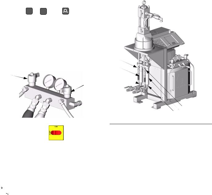
4. Turn PRESSURE RELIEF/SPRAY valves (SA, SB) |
D |
to PRESSURE RELIEF. |
E |
|
|
SA |
C |
SB |
|
TI3593a
FIG. 1. Pump Removal
5. Turn main power OFF |
. Disconnect power |
supply.
C E |
D |
TI3582b |
6.Disconnect hoses and fittings from fluid inlets (C) and outlets (D). See FIG. 1.
7.Remove pump. See applicable manuals, supplied.
 See page 4 for applicable pump and motor repair-parts manuals. Displacement pumps (E) may be removed without removing entire proportioning pump.
8. Reinstall in reverse order.
309813H |
15 |
Loading...