


 Loading...
Graco GL-1 X, GL-1 XL, 24X801, 24X802, 24X803 Instruction manual
...
Instructions-Parts List
GL-1 X™, GL-1 XL™
Injectors |
335023J |
EN |
For Single–Line Parallel Automatic Lubrication Systems
Important Safety Instructions

 Read all warnings and instructions in this manual and in related Automatic Lubrication System instruction manuals. Save all instructions.
Maximum Working Pressure: 6000 psi (41 MPa, 414 bar)
Models:
See page 2
GL-1 X Model |
GL-1 XL Model |
|
|
|
|

Models
Models
GL-1 X Injector Models
|
Part No. |
|
Description |
Dimension A* |
Dimension B* |
Bare Manifold |
|
|
Part No. |
||||
|
24X801 |
Injector, GL-1 X, one point |
|
2.48 in. (63.0 mm) |
114911 |
|
|
24X802 |
Injector, GL-1 X, two point |
|
3.00 in. (76.0 mm) |
114912 |
|
|
24X803 |
Injector, GL-1 X, three point |
1.25 in. (31.7 mm) |
4.23 in. (107.5 mm) |
114913 |
|
|
24X804 |
Injector, GL-1 |
X, four point |
2.50 in. (63.4 mm) |
5.47 in. (139.0 mm) |
114914 |
|
24X805 |
Injector, GL-1 |
X, five point |
3.75 in. (95.1 mm) |
6.71 in. (170.5 mm) |
114915 |
|
24X806 |
Injector, GL-1 |
X, six point |
5.00 in. (126.8 mm) |
7.98 in. (202.7 mm) |
118206 |
|
24X807 |
Injector, GL-1 |
X, replacement |
|
|
|
GL-1 XL Injector Models |
|
|
|
|||
Part No. |
|
Description |
Dimension A* |
Dimension B* |
Bare Manifold |
|
Part No. |
||||
24X811 |
Injector, GL-1 XL, one point |
|
2.48 in. (63.0 mm) |
114911 |
|
24X812 |
Injector, GL-1 XL, two point |
|
3.00 in. (76.0 mm) |
114912 |
|
24X813 |
Injector, GL-1 XL, three point |
1.25 in. (31.7 mm) |
4.23 in. (107.5 mm) |
114913 |
|
24X814 |
Injector, GL-1 |
XL, four point |
2.50 in. (63.4 mm) |
5.47 in. (139.0 mm) |
114914 |
24X815 |
Injector, GL-1 |
XL, five point |
3.75 in. (95.1 mm) |
6.71 in. (170.5 mm) |
114915 |
24X816 |
Injector, GL-1 |
XL, six point |
5.00 in. (126.8 mm) |
7.98 in. (202.7 mm) |
118206 |
24X817 |
Injector, GL-1 |
XL, Replacement |
|
|
|
*See Dimensions, page 11
2 |
335023J |

Warnings
Warnings
The following warnings are for the setup, use, grounding, maintenance, and repair of this equipment. The exclamation point symbol alerts you to a general warning and the hazard symbols refer to procedure-specific risks. When these symbols appear in the body of this manual or on warning labels, refer back to these Warnings. Product-specific hazard symbols and warnings not covered in this section may appear throughout the body of this manual where applicable.
 WARNING
SKIN INJECTION HAZARD
High-pressure fluid from injector, hose leaks, or ruptured components will pierce skin. This may look like just a cut, but it is a serious injury that can result in amputation. Get immediate surgical treatment.
•Do not put your hand over the fluid outlet.
• Do not stop or deflect leaks with your hand, body, glove, or rag.
+• Relieve pressure before cleaning, checking, or servicing equipment.
• Tighten all fluid connections before operating the equipment.
PERSONAL PROTECTIVE EQUIPMENT
Wear appropriate protective equipment when in the work area to help prevent serious injury, including eye injury, hearing loss, inhalation of toxic fumes, and burns. This protective equipment includes but is not limited to:
•Protective eyewear, and hearing protection.
•Respirators, protective clothing, and gloves as recommended by the fluid and solvent manufacturer.
CALIFORNIA PROPOSITION 65
This product contains a chemical known to the State of California to cause cancer, birth defects or other reproductive harm. Wash hands after handling.
335023J |
3 |
Installation Instructions
Installation Instructions
Reference letters used in the following instructions, refer to FIG. 1.
NOTICE
Contaminants can damage the seal packing. To prevent damage to the seal, a filter should be installed in the grease supply line.
•Group injectors to minimize feed line length.
•Install injectors in locations that allow easy servicing access.
•To avoid injector damage install injectors in areas away from moving equipment.
•Injector outputs can be combined for a common bearing point with a large grease requirement but the output for a single injector cannot be split into multiple bearing points.
•Graco recommends using steel tubing instead of pipe and hose for supply lines when possible. Pipe is often contaminated with scale and requires proper cleaning prior to use. Hose lines expand under pressure which leads to longer pump cycle time.
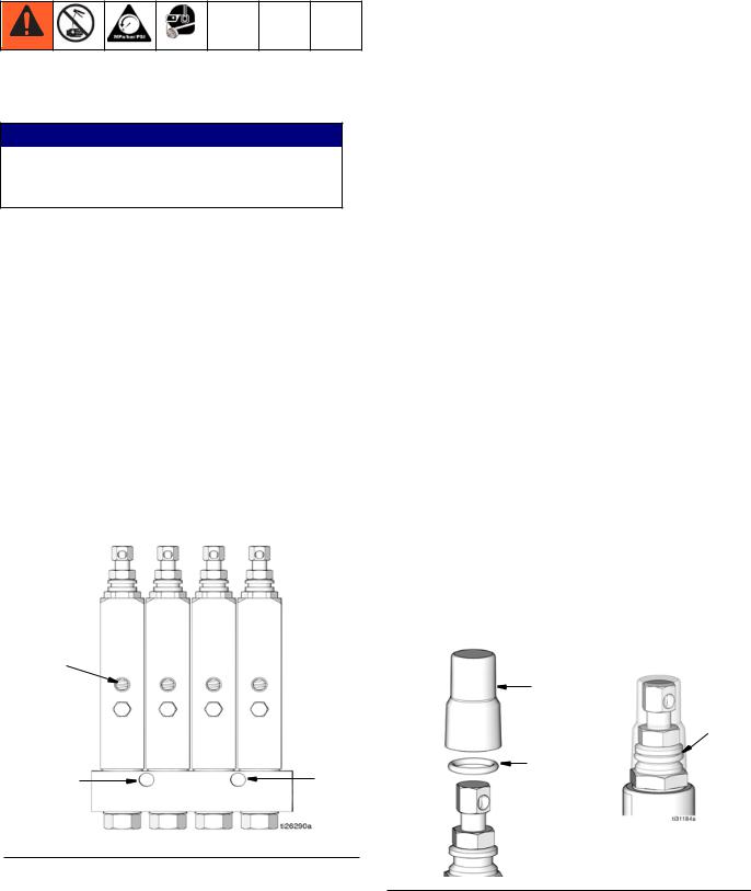
b
a |
a |
NOTE: The equipment may be pressurized by an automatic lube cycle initiated by a lubrication controller (timer).
1.Before installing the injectors, disconnect and isolate the power supplies to the lubrication controller and to the pump.
2.Relieve pressure. See the pressure relief procedure provided in the pump manual for your system.
3.Install injectors on a flat, hard surface using holes
(a) (FIG. 1) in manifold.
4.Connect fluid supply line to injectors.
5.Connect lube point feed lines to outlet (b).
6.Flush the system with low viscosity oil or mineral spirits to remove contamination introduced during installation.
7.Use a purge gun or run the pump until clean lubricant is dispensed at the end of each feed line to purge the system of flushing fluid or air.
8.Run the system at full output and verify that all injectors are cycling.
9.Adjust injector volume output. (See Volume Adjustment page 5.)
10.Connect feed lines to lubrication points.
Injector Cap (FIG. 2)
1.Apply a light coating of transparent lubricant to the inside of cap (c).
2.Slide the o-ring (d) over the indicator stem of the injector and into the groove.
3.Slide cap (c) down over the indicator stem of the injector.
c
groove
d
FIG. 1: GL-1 X model injector shown
FIG. 2
4 |
335023J |
Loading...