


 Loading...
Instructions and Parts
SaniForce™ 12:1
Sanitary Pumps
3A0735J
EN
For use in sanitary applications to transfer medium to high viscosity fluids. For professional use only.
See page 2 for model information, including maximum fluid working pressure.
Important Safety Instructions

 Read all warnings and instructions in this manual. Save these instructions.
ti15718a
Models
Contents
Models . . . . . . . . . . . . . . . . . . . . . . . . . . . . . . . . . . . 2
Warnings . . . . . . . . . . . . . . . . . . . . . . . . . . . . . . . . . 4
Installation . . . . . . . . . . . . . . . . . . . . . . . . . . . . . . . . 6
Grounding . . . . . . . . . . . . . . . . . . . . . . . . . . . . . . 6
Mounting . . . . . . . . . . . . . . . . . . . . . . . . . . . . . . . 6
Setup . . . . . . . . . . . . . . . . . . . . . . . . . . . . . . . . . . 6
Operation . . . . . . . . . . . . . . . . . . . . . . . . . . . . . . . . . 8
Pressure Relief Procedure . . . . . . . . . . . . . . . . . 8
Flush Before First Use . . . . . . . . . . . . . . . . . . . . 8
Adjusting the Pump Speed and Pressure . . . . . . 8
Pump Shutdown . . . . . . . . . . . . . . . . . . . . . . . . . 8
Maintenance . . . . . . . . . . . . . . . . . . . . . . . . . . . . . . . 9
Flushing Procedure . . . . . . . . . . . . . . . . . . . . . . . 9
Cleaning Procedure . . . . . . . . . . . . . . . . . . . . . . 9
Tighten Connections . . . . . . . . . . . . . . . . . . . . . . 9
Troubleshooting . . . . . . . . . . . . . . . . . . . . . . . . . . . 10
Service . . . . . . . . . . . . . . . . . . . . . . . . . . . . . . . . . . 11
Disconnect the Pump . . . . . . . . . . . . . . . . . . . . 11
Disassemble the Pump . . . . . . . . . . . . . . . . . . . 11
Reassemble the Pump . . . . . . . . . . . . . . . . . . . 13
Reconnect the Pump . . . . . . . . . . . . . . . . . . . . . 14
Parts . . . . . . . . . . . . . . . . . . . . . . . . . . . . . . . . . . . . 16
Complete Pump Models 24F625
and 24F626 . . . . . . . . . . . . . . . . . . . . . . . . . 16
Kits . . . . . . . . . . . . . . . . . . . . . . . . . . . . . . . . . . . 17
Displacement Pump Models 24G761
and 24G762 . . . . . . . . . . . . . . . . . . . . . . . . 18
Displacement Pump Models 24G761
and 24G762 . . . . . . . . . . . . . . . . . . . . . . . . 19
Kits . . . . . . . . . . . . . . . . . . . . . . . . . . . . . . . . . . . 19
Dimensions . . . . . . . . . . . . . . . . . . . . . . . . . . . . . . . 21
Performance Chart . . . . . . . . . . . . . . . . . . . . . . . . . 22
Technical Data . . . . . . . . . . . . . . . . . . . . . . . . . . . . 23
Graco Standard Warranty . . . . . . . . . . . . . . . . . . . 24
Models
Maximum Air Inlet Pressure: 100 psi (0.7 MPa, 6.9 bar)
Maximum Fluid Working Pressure: 1450 psi (10.1 MPa, 100.4 bar)
Pump |
Displacement |
|
|
|
Model |
Pump Model |
Pump Type |
Pump Description |
Packings |
|
|
|
|
|
24F625 |
24G761 |
Priming Piston |
Stubby |
Acetal, PTFE, Nitrile, and UHMWPE |
|
|
|
|
|
24F626 |
24G762 |
Priming Piston |
Stubby, with extra seal* |
Acetal, PTFE, Nitrile, and UHMWPE |
|
|
|
|
|
* For use with viscous, sticky material.
2 |
3A0735J |
Models
Material Certification
Reference: SaniForce Product Family
Issue Date: September 14, 2011
All fluid contact materials in the SaniForce product family are FDA-Compliant and meet the United States Code of Federal Regulations (CFR) Title 21, Section 177 or are of a corrosion resistant grade Stainless Steel. This includes the below product groups:
1.SaniForce 1040, 1590, 2150 Air-Operated Double Diaphragm Pumps
2.SaniForce 1590, 3150 HS Air-0perated Double Diaphragm Pumps
3.SaniForce 1590, 3150 HS 3-A Certified Air-Operated Double Diaphragm Pumps
4.SaniForce 5:1, 6:1 and 12:1 Air-Operated Piston Pumps
5.SaniForce Diaphragm Pump and Piston Pump Drum Unloaders
6.SaniForce Diaphragm Pump and Piston Pump Bin Evacuation Systems
Bradley A. Byron
Quality Manager
Graco Inc.
3A0735J |
3 |
Warnings
Warnings
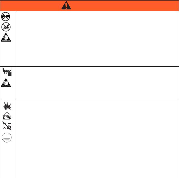
The following warnings are for the setup, use, grounding, maintenance, and repair of this equipment. The exclamation point symbol alerts you to a general warning and the hazard symbols refer to procedure-specific risks. When these symbols appear in the body of this manual, refer back to these Warnings. Product-specific hazard symbols and warnings not covered in this section may appear throughout the body of this manual where applicable.
WARNING
SKIN INJECTION HAZARD
High-pressure fluid from dispensing device, hose leaks, or ruptured components will pierce skin. This may look like just a cut, but it is a serious injury that can result in amputation. Get immediate surgical treatment.
+
• Do not point dispensing device at anyone or at any part of the body.
• Do not put your hand over the fluid outlet.
• Do not stop or deflect leaks with your hand, body, glove, or rag.
• Follow the Pressure Relief Procedure when you stop dispensing and before cleaning, checking, or servicing equipment.
• Tighten all fluid connections before operating the equipment.
• Check hoses and couplings daily. Replace worn or damaged parts immediately.
MOVING PARTS HAZARD
Moving parts can pinch, cut or amputate fingers and other body parts.
•Keep clear of moving parts.
•Do not operate equipment with protective guards or covers removed.
•Pressurized equipment can start without warning. Before checking, moving, or servicing equipment, follow the Pressure Relief Procedure and disconnect all power sources.
FIRE AND EXPLOSION HAZARD
Flammable fumes, such as solvent and paint fumes, in work area can ignite or explode. To help prevent fire and explosion:
• Use equipment only in well ventilated area.
• Eliminate all ignition sources; such as pilot lights, cigarettes, portable electric lamps, and plastic drop cloths (potential static arc).
• Keep work area free of debris, including solvent, rags and gasoline.
• Do not plug or unplug power cords, or turn power or light switches on or off when flammable fumes are present.
•Ground all equipment in the work area. See Grounding instructions.
•Use only grounded hoses.
•Hold gun firmly to side of grounded pail when triggering into pail.
•If there is static sparking or you feel a shock, stop operation immediately. Do not use equipment until you identify and correct the problem.
•Keep a working fire extinguisher in the work area.
4 |
3A0735J |

Warnings
 WARNING
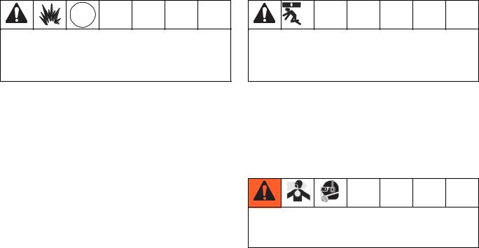
EQUIPMENT MISUSE HAZARD
Misuse can cause death or serious injury.
•Do not operate the unit when fatigued or under the influence of drugs or alcohol.
•Do not exceed the maximum working pressure or temperature rating of the lowest rated system component. See Technical Data in all equipment manuals.
•Use fluids and solvents that are compatible with equipment wetted parts. See Technical Data in all equipment manuals. Read fluid and solvent manufacturer’s warnings. For complete information about your material, request MSDS from distributor or retailer.
•Do not leave the work area while equipment is energized or under pressure. Turn off all equipment and follow the Pressure Relief Procedure when equipment is not in use.
•Check equipment daily. Repair or replace worn or damaged parts immediately with genuine manufacturer’s replacement parts only.
•Do not alter or modify equipment.
•Use equipment only for its intended purpose. Call your distributor for information.
•Route hoses and cables away from traffic areas, sharp edges, moving parts, and hot surfaces.
•Do not kink or over bend hoses or use hoses to pull equipment.
•Keep children and animals away from work area.
•Comply with all applicable safety regulations.
SPLATTER HAZARD
Hot or toxic fluid can cause serious injury if splashed in the eyes or on skin. During blow off of platen, splatter may occur.
• Use minimum air pressure when removing platen from drum.
TOXIC FLUID OR FUMES HAZARD
Toxic fluids or fumes can cause serious injury or death if splashed in the eyes or on skin, inhaled, or swallowed.
•Read MSDSs to know the specific hazards of the fluids you are using.
•Store hazardous fluid in approved containers, and dispose of it according to applicable guidelines.
PERSONAL PROTECTIVE EQUIPMENT
You must wear appropriate protective equipment when operating, servicing, or when in the operating area of the equipment to help protect you from serious injury, including eye injury, hearing loss, inhalation of toxic fumes, and burns. This equipment includes but is not limited to:
•Protective eyewear, and hearing protection.
•Respirators, protective clothing, and gloves as recommended by the fluid and solvent manufacturer.
3A0735J |
5 |
Installation
Installation
Grounding |
Mounting |
||||||||||||
|
|
|
|
|
|
|
|
|
|
|
|
|
|
|
|
|
|
|
|
|
|
|
|
|
|
|
|
|
|
|
|
|
|
|
|
|
|
|
|
|
|
|
|
|
|
|
|
|
|
|
|
|
|
|
|
|
|
|
|
|
|
|
|
|
|
|
|
|
|
|
|
|
|
|
|
|
|
|
|
|
|
|
|
|
|
|
|
|
|
|
|
|
|
|
|
|
|
|
|
|
|
|
|
|
|
|
|
|
|
|
|
|
|
|
|
|
|
|
|
|
|
|
|
|
|
The equipment must be grounded. Grounding reduces the risk of static and electric shock by providing an escape wire for the electrical current due to static build up or in the event of a short circuit.
Pump: Connect a ground wire (Graco PN 238909) to the ground screw on the bottom cover of the air motor, under the shroud. Connect the other end of the ground wire to a true earth ground.
Air and fluid hoses: use only electrically conductive hoses with a maximum of 500 ft. (150 m) combined hose length to ensure grounding continuity. Check electrical resistance of hoses. If total resistance to ground exceeds 25 megohms, replace hose immediately.
Air compressors: follow manufacturer’s recommendations.
Dispense valve: ground through connection to a properly grounded fluid hose and pump.
Material supply container: follow local code.
Container(s) that receive material: follow local code.
Solvent pails used when flushing: follow local code. Use only conductive metal pails, placed on a grounded surface. Do not place the pail on a nonconductive surface, such as paper or cardboard, which interrupts grounding continuity.
To maintain grounding continuity when flushing or relieving pressure: hold metal part of the dispense valve firmly to the side of a grounded metal pail, then trigger the valve.
To avoid injury from a falling pump, check the torque on the lift ring (16) and nut (15) before using the lift ring to lift the pump. Torque to 30-36 ft-lb
(41-49 N•m).
Mount the pump on a surface than can support the weight of the pump and accessories, as well as the stress caused during operation. Do not use air or fluid lines to support the pump.
Setup
To avoid contaminating the fluid, pipe the exhaust air to vent outside of the fluid product area, away from people, animals, or food-handling areas.
NOTE: Reference numbers and letters in parentheses in the text refer to the callouts in the figures and the parts drawings.
Accessories are available from Graco. Make certain all accessories are sized and pressure-rated to meet your system requirements.
FIG. 1 is only a guide for selecting and installing system components and accessories. Contact your Graco distributor for assistance in designing a system to suit your particular needs.
Install a bleed-type master air valve (G) close to the pump air inlet (D), to relieve air trapped between it and the air motor.
Install an air filter/regulator (F) in the pump air line, upstream from the bleed valve, to control air inlet pressure and to remove harmful dirt and contaminants from your compressed air supply.
6 |
3A0735J |

Installation
Install a pump runaway valve (S) in the pump air line to shut off air to the air motor automatically if the pump starts to run too fast.
Install another bleed-type master air valve (G) upstream from all air line accessories and use it to isolate the accessories during cleaning and repair.
On the air drop to the dispense valve (K), install an air regulator (M) to control air pressure to the valve. Install a bleed valve (G) to use as a shutoff when servicing the dispense valve.
Connect air solenoid valves (H) to a timer control (L), and set so the dispense valve (K) will dispense at proper intervals.
|
|
Main Air Line |
|
|
|
|
G |
H |
|
|
|
|
|
|
G D |
A |
C |
|
|
|
|
|
|
G |
M |
H |
L |
|
|
|
K |
|||
|
|
|
N |
|
|
|
J F S
R
E |
|
B |
|
J |
P |
ti15638a
FIG. 1. Typical installation
Key:
Pump Components (Included) |
System Components/Accessories (sold separately) |
|
A Bung-Mounted Sanitary Pump |
F |
Air Line Filter/Regulator |
B Air Exhaust Muffler (may alternately be mounted remotely, |
G |
Bleed-Type Master Air Valve (required) |
using exhaust hose) |
H |
Air Solenoid Valve |
C 3/4 npt Exhaust Air Outlet |
J |
Air Line Drain Pipe and Valve |
D 1/2 npt Air Inlet |
K |
Dispensing Valve |
E 1-1/2 in. Tube Size Flanged Fluid Outlet |
L |
Timer Control |
|
M |
Air Regulator |
|
N |
Dispensing Valve Air Exhaust Hose |
|
P |
Sensing Device |
|
R |
Pump Ground Wire (required) |
|
S |
Pump Runaway Valve |
3A0735J |
7 |

Operation
Operation
NOTICE
Do not expose the air motor to temperatures higher than 120°F (49°C) or the immersed fluid pump to temperatures higher than 160°F (71°C). Excessive temperatures may damage the pump packings and seals.
Pressure Relief Procedure
Trapped air can cause the pump to cycle unexpectedly, which could result in serious injury from injection, splashing, or moving parts. Relieve pressure when you stop pumping and before cleaning, checking, or servicing equipment.
1.Shut off the air supply to the pump.
2.Close the bleed-type master air valve (required in system).
3.Open the fluid ball valve and/or dispensing valve to relieve fluid pressure.
Adjusting the Pump Speed and
Pressure
Set pressure regulator to 0 psi. Open the bleed-type master air valve. Adjust the pump air regulator until the pump is running smoothly.
Allow the pump to cycle slowly until all air is pushed out of the lines (the fluid will flow in a steady stream from the fluid outlet) and the pump is primed.
With the air supply turned on, the pump will start when the dispensing valve is opened and stall against pressure when the valve is closed. In a circulating system, the pump operates until the air supply is turned off.
NOTICE
Never allow the pump to run dry of fluid. A dry pump will accelerate to a high speed, possibly damaging itself.
If the pump accelerates quickly, or is running too fast, stop the pump immediately and check the fluid supply. If the supply is empty and air has been pumped into the lines, refill the container and prime the pump and lines with fluid. Be sure to eliminate all air from the system.
Flush Before First Use
The sanitary pump was assembled using sanitary lubricant on moving parts and was tested in water. Flush the pump thoroughly with an appropriate cleaning solution, and disassemble and sanitize the parts before using the pump. See Flushing Procedure, page 9. Check national, state, and local codes for specific limitations.
Pump Shutdown
Follow the Pressure Relief Procedure, page 8. Always stop the pump at the bottom of its stroke to prevent fluid from drying on the displacement rod. (The air motor will exhaust at the bottom and top of the stroke.)
8 |
3A0735J |
Loading...