


DM74LS193N
© 2000 Fairchild Semiconductor Corporation DS006406 www.fairchildsemi.com
September 1986
Revised March 2000
DM74LS193 Synchronous 4-Bit Binary Counter with Dual Clock
DM74LS193
Synchronous 4-Bit Binary Counter with Dual Clock
General Description
The DM74LS193 circuit is a synchronous up/down 4-bit
binary counter. Synchronous oper ation i s pro vide d by ha v-
ing all flip-flops c locked sim ult a neo usly, so that the o utp uts
change together when so instr ucted by the steering logic.
This mode of operation eliminates the output counting
spikes normally associated with asynchronous (ripple-
clock) counters.
The outputs of the four master-slave flip-flops are triggered
by a LOW-to-HIGH level transition of either count (clock)
input. The direction of counting is determined by which
count input is pulsed while the oth er count input is held
HIGH.
The counter is fully programmable; that is, each output may
be preset to either le vel b y en ter ing the de si red da ta at t he
inputs while the load inpu t is LOW. The output will ch ange
independently of the count pul ses. This feat ure allows t he
counters to be used as modulo-N divi ders by simply mo di-
fying the count length with the preset inputs.
A clear input has been pr ovided which, when taken to a
high level, forces all out puts to the low leve l; independent
of the count and load in puts. The clear, count, and load
inputs are buffered to lower the driv e req uire me nts of clock
drivers, etc., required for long words.
These counters we re d esign ed to be cascaded witho ut the
need for external circu itry. Both borrow and carry outputs
are available to cascade both th e up and down counting
functions. The borrow output produces a pulse equal in
width to the count down input when the counter underflows.
Similarly, the carry output produces a pulse equ al in width
to the count d own in pu t when an overf low condition exists.
The counters can the n be easily cascaded b y feeding the
borrow and carr y outputs to th e count d own and cou nt up
inputs respectively of the succeeding counter.
Features
■ Fully independent clear input
■ Synchronous operation
■ Cascading circuitry provided internally
■ Individual preset each flip-flop
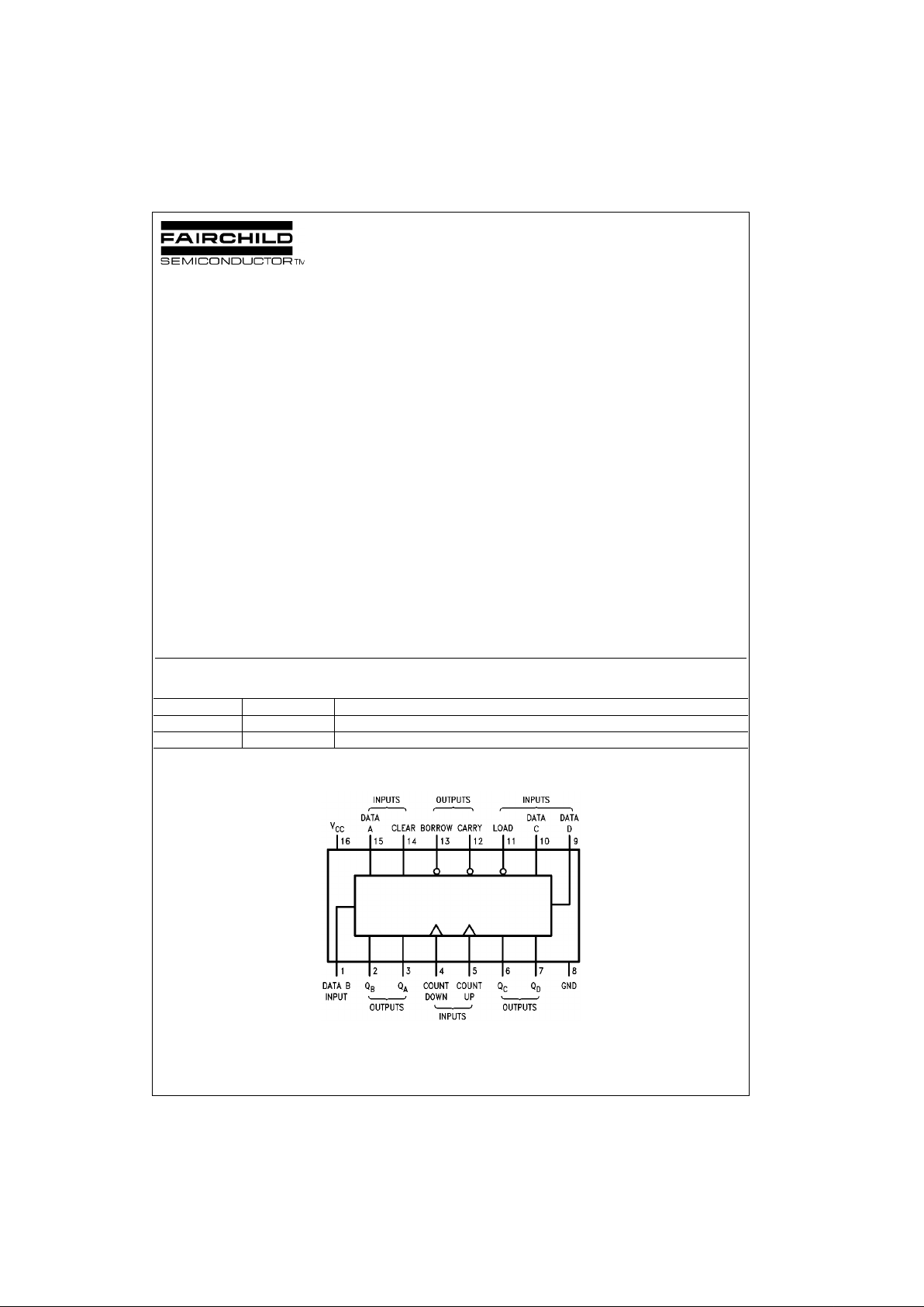
Ordering Code:
Connection Diagram
Order Number Package Number Package Description
DM74LS193M M16A 16-Lead Small Outline Integrated Circuit (SOIC), JEDEC MS-012, 0.150” Narrow Body
DM74LS193N N16E 16-Lead Plastic Dual-In-Line Package (PDIP), JEDEC MS-001, 0.300” Wide
www.fairchildsemi.com 2
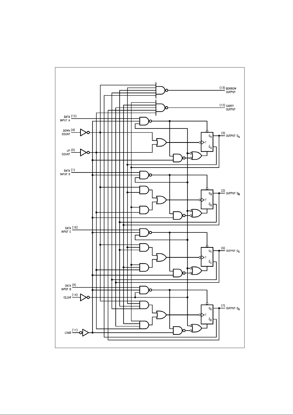
DM74LS193
Logic Diagram
3 www.fairchildsemi.com
DM74LS193
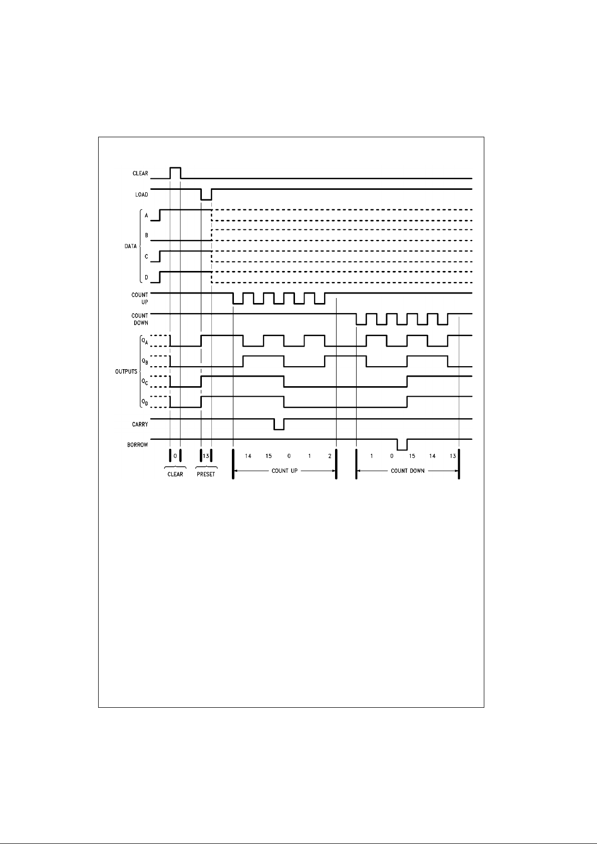
Timing Diagram
Note A: Clear overrides load, data, and count inputs
Note B: When counting up, count-down input must be HIGH; when counting down, count-up input must be HIGH.
 Loading...