


DMC-1002
SNMP Module for
Chassis-Based Media Converter
Manual
Rev. 01 (JUN. 2002)
1907MCB10016000
RECYCLABLE

TABLE OF CONTENTS |
|
ABOUT THIS GUIDE .................................................................. |
2 |
FEATURES ........................................................................................................ |
2 |
UNPACKING ..................................................................................................... |
2 |
CONFIGURING THE SYSTEM .......................................... |
3 |
THE MEDIA CONVERTER CHASSIS SYSTEM .................................................... |
3 |
INSTALLING THE MANAGEMENT MODULE...................................................... |
3 |
CONFIGURE THROUGH WEB BROWSER............................................................ |
4 |
CONFIGURATION VIA SERIAL PORT................................................................. |
4 |
SUPPORT SNMP MANAGEMENT ..................................................................... |
5 |
LED INDICATORS ............................................................................................ |
5 |
MANAGEMENT SETTING THROUGH WEB |
|
BROWSER............................................................................................ |
6 |
MANAGEMENT SETTING THROUGH |
|
TERMINAL EMULATOR...................................................... |
13 |
WHEN FORGOT THE PASSWORD..................................................................... |
19 |
TECHNICAL SPECIFICATIONS .................................... |
20 |
1

ABOUT THIS GUIDE
This manual shows you how to configuring your DMC-1002 SNMP Module for Chassis-Based Media Converter.
Features
Compliant with IEEE802.3u 100BASE-TX standards
Enable to monitor the module through terminal emulation program and Web browser
The network administrator can access management software by connecting the management module either to a terminal emulation program (through the RS232 interface) or to a remote network management station (through the RJ45 interface and a hub)
Status indication include:
1.Identification of: Media Converter type; Slot number occupied
2.Status Indication of Chassis: Redundant Power status; Power Fail status; Fan Fail status
3.Status Indication of Modules: Unit Power; Link/Activity; Transmit; Receive
LED Indication: Power/Power Fail/Fan Fail/MGM/Console/Link/ACT
Support Hot-swappable
Auto-negotiation for half-duplex/full-duplex on TX ports
Equipped with a 19” system chassis 16-converter with Redundant Power supply for optional Expansion use.
Unpacking
Open the shipping carton of the SNMP Module and carefully unpack its contents. The carton should contain the following items:
One DMC-1002 SNMP Module for Chassis-Based Media Converter
One RS232 cable
This Manual
If any item is found missing or damaged, please contact your local reseller for replacement.
2

CONFIGURING THE SYSTEM
This chapter provides network managers and system administrators with information about how to configure the Media Converter Chassis system.
The reader of this document should be knowledgeable about network devices, device configuration, network management, and Internet browsers. The user is assumed to be a network administrator or manager with an understanding of network operations.
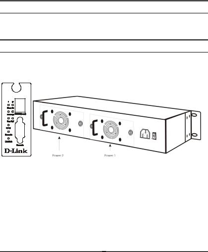
The Media Converter Chassis system
The chassis’s first slot is for the management module as illustration on figure 1.
Figure 1. Slide in the management module in the first slot of the chassis system.
Installing the Management Module
Before Configure the chassis system, you must do the following:
Install the management module into the chassis. (Figure 1)
Connect the module to the network.
Boot up for SNMP management on Web browser or emulation terminal program.
3

Configure through Web browser
The Media Converter chassis system is accessible using a Web browser (IE explorer, Netscape Communications, etc.) to open up the chassis monitoring system. The default IP Address for the chassis system is “192.168.1.1”, and the default Login name and password is both “root”.
Configuration via Serial Port
The Media Converter chassis system can be accessible using a terminal or terminal emulator attached to the RS232 serial port on the Switch too.
NOTE: (1) The serial port cable is attached directly with the device.
(2) It needs to upgrade the Terminal Emulator due to key malfunction.
1.Locate correct DB9 serial port cable with female DB9 connector.
2.Attach the DB9 serial port female cable connector to the male DB9 serial port connector on the chassis system.
3.Attach the other end of the DB9 serial port cable to a remote workstation.
4.By default, the Switch uses the following serial port parameter values:
Bits per second |
57600 |
Stop bits |
1 |
Data bits |
8 |
Parity |
NONE |
Flow Control |
NONE |
|
|
4
5.The default Login name and password is both “root”.
Support SNMP Management
The Media Converter Management Module support SNMP management.
LED Indicators
The LED indicators of the Switch include Power, ALERT, HTTP, ICQ, SMTP, SPEED, LINK/ACT and FDX/COL. The following shows the LED indicators for the Switch along with an explanation of each indicator.
DMC1000i
Power On: Lights green when the power is inserted.
Power Fail: Lights Amber when the power is inserted and it is fail.
Fan Fail: Lights Amber when the fan is fail.
MGM: |
Blinks green when the device CPU is working and |
|
lights amber when the CPU works fail. |
Console: Blinks green when the data is transmitting through console port and blinks amber when transmitting the wrong data.
5
Link/Act: Lights green when link to networking Ethernet and blinks green for activity.
MANAGEMENT SETTING THROUGH WEB
BROWSER
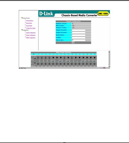
1 Main Menu
Figure (1) Main Menu
1-1 System Function
There are four items in System Function menu, “Softw are Reboot, Factory Reset, Image Update and Configuration Update. (Figure 2)
1-2 Configuration
There are three items in Configuration menu, “Genera l Configuration, System Configuration and SNMP Configuration. (Figure 2)
6
 Loading...