


 Loading...
DI-1162/DI-1162M
RemoteAccessRouter
User’sGuide
First Edition (August 2000)
6DI1162M..01 Printed In Taiwan
RECYCLABLE
Limited Warranty
Hardware:
D-Link warrants each of its hardware products to be free from defects in workmanship and materials under normal use and service for a period commencing on the date of purchase from D-Link or its Authorized Reseller and extending for the length of time stipulated by the Authorized Reseller or D-Link Branch Office nearest to the place of purchase.
This Warranty applies on the condition that the product Registration Card is filled out and returned to a D-Link office within ninety (90) days of purchase. A list of D-Link offices is provided at the back of this manual, together with a copy of the Registration Card.
If the product proves defective within the applicable warranty period, D-Link will provide repair or replacement of the product. D-Link shall have the sole discretion whether to repair or replace, and replacement product may be new or reconditioned. Replacement product shall be of equivalent or better specifications, relative to the defective product, but need not be identical. Any product or part repaired by D-Link pursuant to this warranty shall have a warranty period of not less than 90 days, from date of such repair, irrespective of any earlier expiration of original warranty period. When D-Link provides replacement, then the defective product becomes the property of D-Link.
Warranty service may be obtained by contacting a D-Link office within the applicable warranty period, and requesting a Return Material Authorization (RMA) number. If a Registration Card for the product in question has not been returned to D-Link, then a proof of purchase (such as a copy of the dated purchase invoice) must be provided. If Purchaser's circumstances require special handling of warranty correction, then at the time of requesting RMA number, Purchaser may also propose special procedure as may be suitable to the case.
After an RMA number is issued, the defective product must be packaged securely in the original or other suitable shipping package to ensure that it will not be damaged in transit, and the RMA number must be prominently marked on the outside of the package. The package must be mailed or otherwise shipped to D-Link with all costs of mailing/shipping/insurance prepaid. D-Link shall never be responsible for any software, firmware, information, or memory data of Purchaser contained in, stored on, or integrated with any product returned to D-Link pursuant to this warranty.
Any package returned to D-Link without an RMA number will be rejected and shipped back to Purchaser at Purchaser's expense, and D-Link reserves the right in such a case to levy a reasonable handling charge in addition mailing or shipping costs.
Software:
Warranty service for software products may be obtained by contacting a D-Link office within the applicable warranty period. A list of D-Link offices is provided at the back of this manual, together with a copy of the Registration Card. If a Registration Card for the product in question has not been returned to a D-Link office, then a proof of purchase (such as a copy of the dated purchase invoice) must be provided when requesting warranty service. The term "purchase" in this software warranty refers to the purchase transaction and resulting license to use such software.
D-Link warrants that its software products will perform in substantial conformance with the applicable product documentation provided by D-Link with such software product, for a period of ninety (90) days from the date of purchase from D-Link or its Authorized Reseller. D-Link warrants the magnetic media, on which D-Link provides its software product, against failure during the same warranty period. This warranty applies to purchased software, and to replacement software provided by D-Link pursuant to this warranty, but shall not apply to any update or replacement which may be provided for download via the Internet, or to any update which may otherwise be provided free of charge.
D-Link's sole obligation under this software warranty shall be to replace any defective software product with product which substantially conforms to D-Link's applicable product documentation. Purchaser assumes responsibility for the selection of appropriate application and system/platform software and associated reference materials. D-Link makes no warranty that its software products will work in combination with any hardware, or any application or system/platform software product provided by any third party, excepting only such products as are expressly represented, in D-Link's applicable product documentation as being compatible. D-Link's obligation under this warranty shall be a reasonable effort to provide compatibility, but D-Link shall have no obligation to provide compatibility when there is fault in the third-party hardware or software. D-Link makes no warranty that operation of its software products will be uninterrupted or absolutely error-free, and no warranty that all defects in the software product, within or without the scope of D-Link's applicable product documentation, will be corrected.
D-Link Offices for Registration and Warranty Service
The product's Registration Card, provided at the back of this manual, must be sent to a D-Link office. To obtain an RMA number for warranty service as to a hardware product, or to obtain warranty service as to a software product, contact the D-Link office nearest you. An address/ telephone/fax/e-mail/Web site list of D-Link offices is provided in the back of this manual.

Trademarks
Copyright 2000 D-Link Corporation. Contents subject to change without prior notice.
D-Link is a registered trademark of D-Link Corporation/D-Link Systems, Inc. All other trademarks belong to their respective proprietors.
Copyright Statement
No part of this publication may be reproduced in any form or by any means or used to make any derivative such as translation, transformation, or adaptation without permission from D-Link Corporation/D-Link Systems Inc., as stipulated by the United States Copyright Act of 1976.
FCC Warning
This equipment has been tested and found to comply with the limits for a Class A digital device, pursuant to Part 15 of the FCC Rules. These limits are designed to provide reasonable protection against harmful interference when the equipment is operated in a commercial environment. This equipment generates, uses, and can radiate radio frequency energy and, if not installed and used in accordance with this user’s guide, may cause harmful interference to radio communications. Operation of this equipment in a residential area is likely to cause harmful interference in which case the user will be required to correct the interference at his own expense.
This device complies with part 15 of the FCC Rules. Operation is subject to the following two conditions: (1) This device may not cause harmful interference, and (2) this device must accept any interference received, including interference that may cause undesired operation.
CE Mark Warning
This is a Class A product. In a domestic environment, this product may cause radio interference in which case the user may be required to take adequate measures.
Warnung!
Dies ist in Produkt der Klasse A. Im Wohnbereich kann dieses Produkt Funkstoerungen verursachen. In diesem Fall kann vom Benutzer verlangt werden, angemessene Massnahmen zu ergreifen.
Precaución!
Este es un producto de Clase A. En un entorno doméstico, puede causar interferencias de radio, en cuyo case, puede requerirse al usuario para que adopte las medidas adecuadas.
Attention!
Ceci est un produit de classe A. Dans un environnement domestique, ce produit pourrait causer des interférences radio, auquel cas l`utilisateur devrait prendre les mesures adéquates.
Attenzione!
Il presente prodotto appartiene alla classe A. Se utilizzato in ambiente domestico il prodotto può causare interferenze radio, nel cui caso è possibile che l`utente debba assumere provvedimenti adeguati.
BSMI Warning

Table of Contents |
|
INTRODUCTION ................................................................................................................................................... |
1 |
Ease of Installation ............................................................................................................................................. |
1 |
Networking Compatibility ................................................................................................................................... |
1 |
PRODUCT FEATURES ............................................................................................................................................... |
1 |
LAN Port ............................................................................................................................................................. |
1 |
Multiple WAN Ports ............................................................................................................................................ |
1 |
Expansion Slot/Modules...................................................................................................................................... |
1 |
Dial on Demand .................................................................................................................................................. |
2 |
Full Network Management.................................................................................................................................. |
2 |
Security................................................................................................................................................................ |
2 |
RIP-1/ RIP-2 Routing Protocols ......................................................................................................................... |
2 |
DHCP Support .................................................................................................................................................... |
2 |
Data Compression............................................................................................................................................... |
2 |
Network Address Translation (NAT/NAPT) ........................................................................................................ |
2 |
APPLICATIONS FOR THE DI-1162/DI-1162M........................................................................................................... |
2 |
Internet Access .................................................................................................................................................... |
3 |
Internet Security .................................................................................................................................................. |
3 |
Link Branch Offices............................................................................................................................................. |
3 |
Local Routing...................................................................................................................................................... |
3 |
Telecommuting .................................................................................................................................................... |
3 |
WHAT THIS MANUAL DOESN’T COVER................................................................................................................... |
3 |
ADDITIONAL INSTALLATION REQUIREMENTS .......................................................................................................... |
3 |
INSTALLATION..................................................................................................................................................... |
4 |
OVERVIEW .............................................................................................................................................................. |
4 |
OTHER RESOURCES................................................................................................................................................. |
4 |
PACKING LIST.......................................................................................................................................................... |
4 |
IDENTIFYING EXTERNAL COMPONENTS................................................................................................................... |
5 |
SITE INSTALLATION ................................................................................................................................................. |
7 |
Rack Mounting .................................................................................................................................................... |
7 |
INSTALLATION AND INITIAL CONFIGURATION OF THE ROUTER ................................................................................ |
7 |
Step 1 - Setting up the Console ........................................................................................................................... |
8 |
Step 2 - Connecting the Console to the Router ................................................................................................... |
8 |
Step 3 - Initial Configuration of the Router ........................................................................................................ |
8 |
Step 3a - Configuring the LAN Port.................................................................................................................. |
10 |
Step 3b - Configuring the WAN Ports for Dial-in, Dial-out and Leased Lines................................................. |
10 |
Step 4 - Connecting the Router to a LAN .......................................................................................................... |
13 |
Step 5 - Connecting the Router to WAN Devices .............................................................................................. |
13 |
Step 6 – Plugging in All Devices....................................................................................................................... |
13 |
Step 7 - Powering Up the DI-1162/DI-1162M.................................................................................................. |
14 |
CONFIGURATION AND MANAGEMENT...................................................................................................... |
15 |
CONSOLE PROGRAM MAIN MENU ......................................................................................................................... |
15 |
SYSTEM INFORMATION.......................................................................................................................................... |
16 |
INTERFACE CONFIGURATION ................................................................................................................................. |
17 |
LAN ................................................................................................................................................................... |
18 |
WAN .................................................................................................................................................................. |
19 |
NETWORK CONFIGURATION .................................................................................................................................. |
22 |
IP Configuration ............................................................................................................................................... |
23 |
IP Static Route .................................................................................................................................................. |
27 |
OSPF Configuration ......................................................................................................................................... |
28 |
Bridge Configuration ........................................................................................................................................ |
34 |

IPX Configuration............................................................................................................................................. |
36 |
SNMP AGENT CONFIGURATION............................................................................................................................ |
41 |
SNMP Community Configuration ..................................................................................................................... |
42 |
SNMP Trap Manager........................................................................................................................................ |
42 |
ADVANCED FUNCTIONS......................................................................................................................................... |
43 |
Remote Access Configuration ........................................................................................................................... |
44 |
Script File Configuration .................................................................................................................................. |
54 |
DHCP Configuration ........................................................................................................................................ |
56 |
Filter Configuration .......................................................................................................................................... |
60 |
Multiple Home Configuration ........................................................................................................................... |
68 |
Static ARP ......................................................................................................................................................... |
70 |
NAT Configuration............................................................................................................................................ |
72 |
NAPT for Special Aps........................................................................................................................................ |
79 |
Telnet/Discovery Enable ................................................................................................................................... |
81 |
DNS Configuration............................................................................................................................................ |
82 |
RADIUS Configuration ..................................................................................................................................... |
83 |
Multi-Link PPP Configuration.......................................................................................................................... |
84 |
ADMIN CONFIGURATION........................................................................................................................................ |
86 |
SYSTEM MAINTENANCE ........................................................................................................................................ |
86 |
System Status..................................................................................................................................................... |
87 |
Counter.............................................................................................................................................................. |
87 |
Runtime Tables.................................................................................................................................................. |
91 |
Log and Trace ................................................................................................................................................... |
96 |
Diagnostic ....................................................................................................................................................... |
101 |
Software Update Menu.................................................................................................................................... |
105 |
System Restart ................................................................................................................................................. |
106 |
Factory Reset .................................................................................................................................................. |
107 |
System Settings Backup/Restore...................................................................................................................... |
108 |
PROM SYSTEM CONFIGURATION.............................................................................................................. |
111 |
PROM System Menu........................................................................................................................................ |
111 |
System Configuration Menu ............................................................................................................................ |
112 |
TCP/IP Parameters Configuration Menu ....................................................................................................... |
113 |
System Reset .................................................................................................................................................... |
113 |
Software Update Menu.................................................................................................................................... |
114 |
Factory Reset .................................................................................................................................................. |
116 |
Execute Bootload ............................................................................................................................................ |
116 |
USING TELNET ................................................................................................................................................. |
117 |
TELNET CONFIGURATION .................................................................................................................................... |
117 |
Using Telnet via LAN ...................................................................................................................................... |
117 |
Using Telnet via WAN ..................................................................................................................................... |
117 |
System Timeout................................................................................................................................................ |
117 |
USING RADIUS AUTHENTICATION ............................................................................................................ |
117 |
INSTALLING A RADIUS SERVER......................................................................................................................... |
118 |
CONFIGURING THE DI-1162/DI-1162M FOR RADIUS AUTHENTICATION........................................................... |
118 |
ADDING USERS TO THE RADIUS DATABASE...................................................................................................... |
119 |
APPENDIX A – CABLES AND CONNECTORS ............................................................................................ |
120 |
RS-232 (EIA-574) for Diagnostic Port............................................................................................................ |
120 |
RS-232 (EIA-530) Cable for WAN Port .......................................................................................................... |
120 |
RS-449 Cable for WAN Port ........................................................................................................................... |
121 |
V.35 Cable for WAN Port................................................................................................................................ |
122 |
APPENDIX B – SPECIFICATIONS ................................................................................................................. |
123 |
APPENDIX C - IP CONCEPTS......................................................................................................................... |
124 |

IP ADDRESSES .................................................................................................................................................... |
124 |
IP Network Classes ......................................................................................................................................... |
124 |
SUBNET MASK .................................................................................................................................................... |
125 |
APPENDIX D – IP PROTOCOL AND PORT NUMBERS............................................................................. |
126 |
IP PROTOCOL NUMBERS ..................................................................................................................................... |
126 |
IP PORT NUMBERS.............................................................................................................................................. |
126 |
APPENDIX E – CONFIGURATION FILE ...................................................................................................... |
127 |
CONFIGURATION FILE EXAMPLE.......................................................................................................................... |
127 |
INDEX .................................................................................................................................................................. |
129 |

DI-1162/DI-1162M Remote Access Router
Introduction
Congratulations on your purchase of a D-Link DI-1162/DI-1162M Remote Access Router. Your new router offers inexpensive yet complete telecommunications and internetworking solutions for your corporate office, school or business. It is ideal for everything from Internet browsing to receiving calls from Remote Dial-in Users. It incorporates the most recent technologies to make fast, secure and stable connections to remote stations via LAN to WAN and vice versa.
Distinguishing features of the DI-1162/DI-1162M include support for a full range of networking protocols such as TCP/IP (Transmission Control Protocol/Internet Protocol), Ethernet, Fast Ethernet as well as various other networking protocols.
Each DI-1162 /DI-1162M router is packed with features that give it the flexibility to provide a complete networking solution for almost any site. The router fulfills the need for Internet access, IP-based intranetworks and LAN to multiple WAN communications.
Ease of Installation
The DI-1162/DI-1162M is a self-contained unit that is quick and easy to install. It is designed to be a standalone unit or it may be mounted on a standard 19-inch networking equipment rack. It uses standard Ethernet wiring to connect (route) a local area network (LAN) to up to 4 separate wide area networks (WANs) through dial-up or dedicated, leased lines.
Also included with the router is the DI-1162/DI-1162M Router Configuration Utility, a Windows-based application that makes configuring the router a snap.
Networking Compatibility
The DI-1162/DI-1162M is compatible with remote access products from other companies such as Ascend, Cisco, and 3Com. Furthermore, it supports Microsoft Windows 95, Windows 98, and Windows NT remote access capability.
Product Features
LAN Port
The DI-1162/DI-1162M is equipped with an auto-negotiated 10/100 (Ethernet and Fast Ethernet) RJ-45 jack for connecting the router to the LAN.
Multiple WAN Ports
The DI-1162/DI-1162M has two EIA-530 WAN ports, each of which can be connected to a dial-up (dial in or out) line or a dedicated leased line by multiplexing with a modem or CSU/DSU (Channel Service Unit/ Data Service Unit) respectively. We recommend connecting only one WAN port to the Internet.
Expansion Slot/Modules
The DI-1162/DI-1162M contains an expansion slot able to house any one of the following slide-in expansion modules:
♦An RJ-45 10/100 Fast Ethernet port, giving the router another LAN connection.
1

DI-1162/DI-1162M Remote Access Router
♦Two high-speed serial (async/sync) ports for two additional WAN connections.
♦A BRI ISDN module (S/T interface only).
These modules allow you to expand the functionality of the DI-1162/DI-1162M to fulfill all your internetworking needs.
Dial on Demand
The Dial-On-Demand feature allows the DI-1162/DI-1162M to automatically place a call to a remote node, via a WAN, whenever there is traffic coming from any workstation on the LAN to that remote site.
Full Network Management
The DI-1162/DI-1162M incorporates SNMP (Simple Network Management Protocol) agents and a menu-driven Network Management System accessible via an RS-232 (console) or Telnet connection.
Security
The DI-1162/DI-1162M supports PAP (Password Authentication Protocol), CHAP (Challenge Handshake Authentication Protocol), Layer 2 and IP Filtering, and the creation of firewalls.
RIP-1/ RIP-2 Routing Protocols
The DI-1162/DI-1162M supports both RIP-1 and RIP-2 (Routing Information Protocol versions 1 and 2) exchanges with adjacent routers. These exchanges allow the DI-1162/DI-1162M to send and/or receive routing tables to adjacent routers in order to streamline WAN communications.
DHCP Support
DHCP (Dynamic Host Configuration Protocol) allows the DI-1162/DI-1162M router to automatically assign IP addresses to computers as they enter the network. This feature frees the network administrator from assigning and managing IP addresses for each individual machine on the LAN.
Data Compression
The DI-1162/DI-1162M incorporates the hardware-based Stac LZS Data Compression for CCP (Compression Control Protocol).
Network Address Translation (NAT/NAPT)
This feature allows multiple users on the LAN to access the Internet (through an Internet Service Provider) concurrently through a single IP address. This is especially useful for corporate office environments, where a large number of users need access to the internet, but only a few internet addresses are available.
Applications for the DI-1162/DI-1162M
Some applications for the DI-1162/DI-1162M include:
2

DI-1162/DI-1162M Remote Access Router
Internet Access
The DI-1162/DI-1162M supports the TCP/IP (a.k.a. IP) protocol, which is the protocol language used for the Internet. This router allows everyone connected to the LAN to access the Internet.
Internet Security
The DI-1162/DI-1162M can act as a firewall between your office network and the Internet, and can hide the size of your office network and the host addresses of your office computers from prying Internet users. It can also filter traffic to and from the Internet allowing only certain types of communications to or from certain locations to pass through.
Link Branch Offices
The DI-1162/DI-1162M routes communications through its two (upgradeable to four) WAN ports allowing direct communications to a branch office via phone lines, the internet or both.
Local Routing
The DI-1162/DI-1162M can route traffic between up to eight local IP networks.
Telecommuting
The DI-1162/DI-1162M allows remote users to dial in and obtain remote access to the LAN. This feature enables users that have workstations with remote access capability, e.g. Windows 95, to dial in using a modem and access the network resources without physically being in the office.
What This Manual Doesn’t Cover
This manual assumes that you are familiar with network management and networking devices, especially routing protocols.
Additional Installation Requirements
In addition to the contents of your package, there are other hardware and software requirements needed before the installation and use of your router. These requirements include:
♦Ethernet connection(s) to your computer(s) to form a LAN.
♦A computer equipped with an RS-232 serial port (standard on most PC’s) and serial line communications software (i.e. Microsoft HyperTerminal included with Windows).
♦At least one modem or CSU/DSU for connecting the WAN port(s) to a telephone line.
♦At least one Internet IP Address per port on the router.
♦An Internet Service Provider (ISP).
3

DI-1162/DI-1162M Remote Access Router
Installation
This chapter details installation procedures for the DI-1162/DI-1162M router.
Overview
The DI-1162/DI-1162M can be configured in two ways; through a direct serial connection (a console), or remotely, through the included Router Configuration Utility, Telnet, etc. Please note that if you wish to remotely configure the router, you must still use a console to initially configure the LAN or WAN port for a remote connection.
In general, the installation procedures are as follows:
1.Physically install the router into an equipment rack or onto a desktop.
2.Configure the router through a console.
3.Power off the router and console.
4.Plug in all cables and connectors (LAN, WAN, etc.).
5.Power on all devices.
Each of the above items is discussed in detail below.
Note: Your LAN does not need to be powered down when making a LAN connection to the router via the RJ-45 port. However, when connecting devices to the WAN or Diagnostic (console) ports please make sure the router and the other devices are turned off before making the connection.
Other Resources
For more information about your DI-1162/DI-1162M please check the following sources:
♦Quick Installation Guide.
♦Support disk containing RouteView, a Windows-based configuration program used to set up and configure the router.
♦Frequently Asked Questions (FAQ) and application notes for this router can be found on the D-Link Web site at http://tsd.dlink.com.tw/.
Packing List
Before you proceed further, please check all items you received with your DI-1162/DI-1162M Router with this list to make sure the package is complete. The complete package should include:
♦One DI-1162 or DI-1162M Router.
♦One 100~240V AC power cord (the plug type depends on the region the router is shipped in).
♦One RS-232 (DB-9 to DB-9) cable for console connection.
♦One 6 ft. (1.83m) Category 5 UTP cable for LAN connection.
♦One EIA-530 (DB-25 to DB-25) cable for WAN connection.
♦Four rubber feet with adhesive backing.
4
DI-1162/DI-1162M Remote Access Router
♦Rack mount kit including six screws and two mounting brackets.
♦One CD-ROM disc or floppy diskette containing the Windows-based Router Configuration Utility.
♦This User’s Guide.
If any item is found missing or damaged, please contact your local D-Link Reseller for replacement.
Identifying External Components
The following section illustrates the different components on the router’s front and rear panels. Before using the router it is highly recommended to familiarize yourself with these components to ensure effective use of the device.
♦LED Indicators The front panel consists of the LED indicators of the router. The LED indicators are used to facilitate monitoring and troubleshooting. Please refer to the following chart for detailed descriptions of these indicators.
5
DI-1162/DI-1162M Remote Access Router
LED |
|
STATUS/ FUNCTION |
|
|
|
Power |
|
Lights whenever the router is plugged in, turned on, and thus |
|
|
receiving power. |
|
|
|
Diag |
|
Lights during the startup Power-On Self-Test (POST) test. |
|
|
|
Boot |
|
Lights briefly during startup after the PROM program has |
|
|
executed. Indicates a successful boot up. |
|
|
|
Run |
|
Should be slowly blinking if the router is functioning properly. |
|
|
|
|
10/100 |
This LED is ON for a 100Mbps link, and OFF for a 10Mbps |
|
|
link. |
|
|
|
|
Link/Act |
This LED is ON to show a good link to the LAN, and quickly |
LAN |
|
flashes to show communication activity on the line. |
|
|
|
|
|
|
|
Full/Half |
This LED is ON for a full-duplex connection, and OFF for |
|
|
half-duplex. |
|
|
|
|
Col |
The LED flashes to show transmission collisions on the line. |
|
|
|
WANs |
Ready |
This LED is ON to show a good modem or CSU/DSU link to |
|
the WAN port. |
|
1 & 2 |
|
|
|
|
|
|
|
|
|
Act |
This LED flashes to show communication activity on the line. |
|
|
|
|
Ready |
This LED is ON to show a good modem or CSU/DSU link to |
Module |
|
the WAN module, or a good link to the LAN port module. |
|
|
|
|
|
|
|
Act |
This LED flashes to show communication activity on the line. |
|
|
|
|
|
|
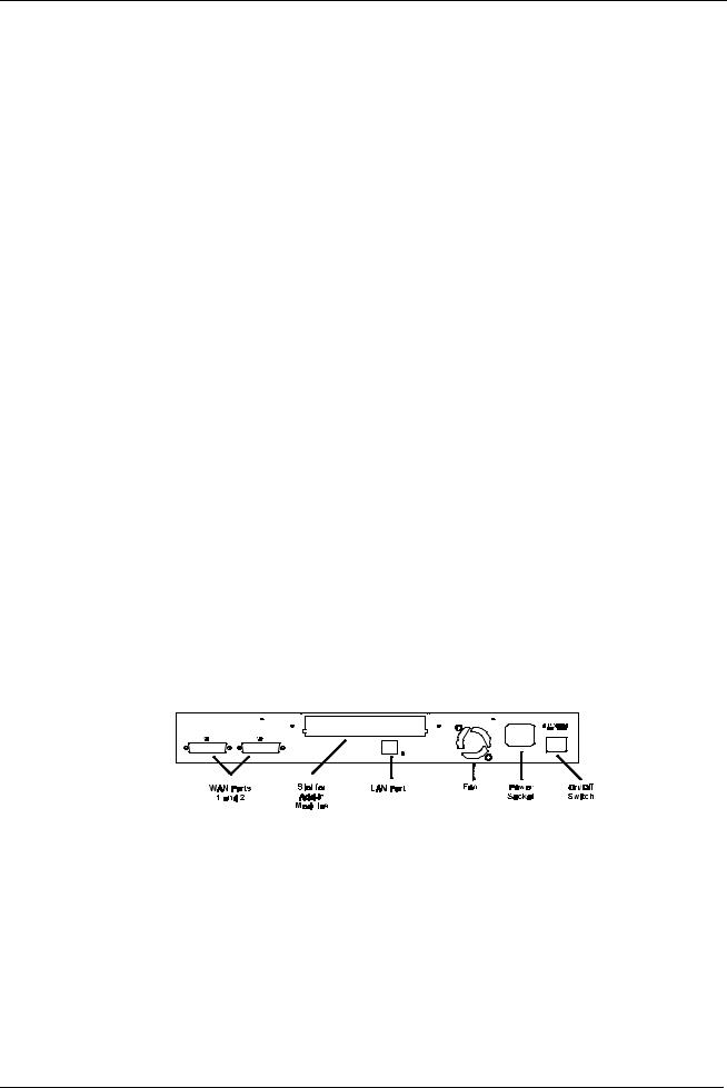
♦Diagnostics RS-232 Serial Port A DB-9 female connector used to connect a console to the router for initial setup and out-of-band management.
♦Wan Ports (1 and 2) Two DB-25 male connectors each of which can be connected to a dial-up (dial in or out) line or a dedicated leased line by multiplexing with a modem or CSU/DSU (Channel Service Unit/ Data Service Unit), respectively.
♦Slot for Add-in Module This slot is able to house any one of the following slide-in expansion modules:
◊A single RJ-45 10/100 Ethernet port
◊Two high-speed serial (async/sync) ports
◊A BRI ISDN module (S/T interface only).
♦LAN Port This jack is a full featured RJ-45 10/100 Ethernet/Fast Ethernet port. This feature allows this port to automatically configure itself to match the settings used by the port it is being connected to. If it is connected
6

DI-1162/DI-1162M Remote Access Router
to another 10/100M auto-negotiation capable port, the two ports will configure themselves to attain the best connection possible.
♦Fan Provides ventilation inside the router. Please ensure to leave adequate space at the rear and sides of the unit for proper ventilation.
♦Power Socket A standard 100~240V socket for the power cord.
♦Power Switch A rocker switch that turns the router off and on.
Site Installation
The site where you install the DI-1162/DI-1162M Router may greatly affect its performance. Please follow these guidelines for setting up the router.
♦Install the router on a sturdy, level surface that can support at least 2 kg of weight. Do not place heavy objects on the router.
♦The power outlet should be within 1.82 meters (6 feet) of the router.
♦Visually inspect the power adapter cord and see that it is fully secured to the power socket.
♦Make sure that there is proper heat dissipation from and adequate ventilation around the router. Leave at least 10 cm of space at the side and rear of the router for ventilation.
♦Install the router in a fairly cool and dry place. See Appendix B for the acceptable temperature and humidity operating ranges.
♦Install the router in a site free from strong electromagnetic field generators (such as motors), vibration, dust, and direct exposure to sunlight.
♦When installing the router on a level surface, attach the rubber feet to the bottom of the device. The rubber feet cushion the router, protect the casing from scratches and prevent it from scratching other surfaces.
Rack Mounting
The DI-1162/DI-1162M may stand alone or be mounted on a standard 19-inch equipment rack. Rack mounting produces an orderly installation when you have a number of related network devices. Use the six supplied screws to fasten the supplied mounting brackets to either end of the router, then fasten the router into the rack.
Installation and Initial Configuration of the Router
This section discusses the different connections that can be made to the router when setting it up.
Initially, you will only wish to connect the console to the router in order to configure the other ports. Once that is complete, you will need to turn off the power to the router and plug in the connection cables to the other devices. Next, power on the other devices. When they have finished powering up, power on the router. Each of these steps is described in detail in the sections below. Please skip any setting adjustments that do not apply to your configuration needs.
A Warning about Connecting Cables
It is important that correct cables are used for each connection; otherwise, the router could be damaged.
Before connecting or disconnecting an RS-232 cable between the DI-1162/DI-1162M and the console and modems, please make sure all devices are off to avoid any chance of damage.
7

DI-1162/DI-1162M Remote Access Router
Step 1 - Setting up the Console
The initial setup of the DI-1162/DI-1162M requires connecting a console to the 9-pin RS-232 Diagnostic port on the router’s front panel. A serial cable is supplied with the router in order to make this connection. A console can be a terminal, such as a VT-100, or a normal PC running terminal emulation software (such as Microsoft HyperTerminal, included with Windows). The terminal emulation software needs to be configured to the following parameters:
◊VT100 terminal emulation
◊9600 baud
◊ No parity, 8 data bits, 1 start bit, 1 stop bit
◊No flow control
Step 2 - Connecting the Console to the Router
A serial cable is included in the DI-1162/DI-1162M package. To connect this cable, plug its nine-pin connector into the 9-pin RS-232 Diagnostic port on the router’s front panel, then connect the other end to the serial port on the rear of your computer or data terminal.
Please make sure both machines are turned off before making this connection.
After the connection is made, first power on the console. If you are using a PC, run the terminal emulation software at this time. After the PC and the terminal emulation software are up and running, power on the router.
Using the Console
The Console Program is the interface that you will be using to configure your DI-1162/DI-1162M. Several operations that you should be familiar with before you attempt to modify the configuration of your router are listed below:
♦Moving Forward to Another Menu To move forward to a submenu below the current one, use Tab or arrow keys to position the cursor on the submenu item and press Enter to view the selected submenu.
♦Moving the Cursor Within a menu, use Tab and arrow keys to navigate through different information fields.
♦Entering Information There are two types of fields that you will need to fill in. The first requires you to type in the appropriate information. The second gives you choices to choose from. In the second case, press the space bar to cycle through the available choices. Upon configuring all fields the submenu, position the cursor on SAVE and press Enter to save, or position the cursor on EXIT to cancel.
♦Refreshing the Screen Console screens are notorious for becoming garbled. When this happens, simply press <Ctrl> + <R> to refresh the contents of the screen.
Step 3 - Initial Configuration of the Router
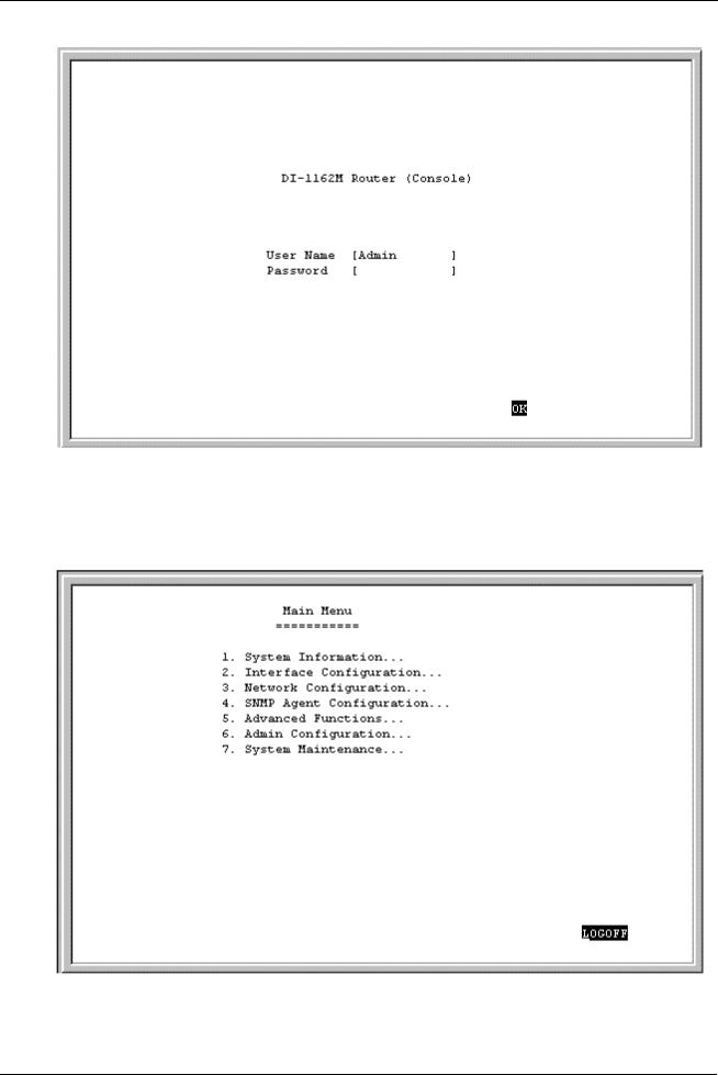
After the console is properly connected and both devices are powered on as described in the preceding sections, you should see the router run through the power on self test (POST). Finally, it will arrive at the logon screen shown below:
8
DI-1162/DI-1162M Remote Access Router
To log on to the router, use the factory set username and password ‘Admin’ (without the quotes). Please note that the user name and password are case-sensitive.
Upon entering the username and password (using the <Tab> key to jump to the next field), position the cursor on OK and press <Enter>. You will then see the following Main Menu:
9

DI-1162/DI-1162M Remote Access Router
Step 3a - Configuring the LAN Port
Preparing the router for connection to a LAN only requires enabling the LAN port, enabling IP networking ,and assigning the LAN port an IP address. After the LAN port is configured, all other features on the router can be configured remotely through the LAN by using the included Windows-based Router Configuration Utility or Telnet.
To configure the LAN:
1.The LAN port must be enabled in the Interface Configuration submenu.
♦Choose Interface Configuration!LAN 1.
♦Position the cursor over the State item and press <space bar>. The State will change from Disable to
Enable.
♦Position the cursor on the Save option at the bottom of the screen and press <Enter> to save the new setting.
♦Choose Exit in the submenus to return to the Main Menu.
2.Enable IP Networking
♦Choose Network Configuration!IP Configuration.
♦Position the cursor on the IP Networking line and press <space bar> to Enable it.
♦Position the cursor on the Save option at the bottom of the screen and press <Enter> to save the new setting.
3.Assign an IP address to the LAN port in the Network Configuration submenu of the Main Menu.
♦Still in Network Configuration!IP Configuration submenu from Step 2 above, choose IP Stack Configuration!LAN 1.
♦Enter a valid IP address for the LAN in the first item. You may also enter a Netmask if you wish. For more information about IP Addresses and Subnet masks, please refer to “Appendix C – IP Concepts.”
♦Position the cursor on the Save option at the bottom of the screen and press <Enter> to save the new setting.
♦Choose Exit in the submenus to return to the Main Menu.
The router can now be accessed via the LAN by Telnet, the Windows-based DI-1162/DI-1162M Router Configuration Utility (included with the router) and other SNMP management applications.
If you have any questions regarding the settings you made or other settings in the submenus, please refer to the next chapter, “Configuration and Management.”
At this point, please proceed to the next initial configuration step.
Step 3b - Configuring the WAN Ports for Dial-in, Dial-out and Leased Lines
Please configure LAN port as described above to familiarize yourself with the configuration program (the LAN port must be configured in any case). Some settings that were made configuring the LAN will be repeated below. Please disregard the instructions below if the setting has already been changed.
10

DI-1162/DI-1162M Remote Access Router
Each WAN port can be configured to either receive dial-in calls (act as a Remote Access Server), dial out to other routers (at branch offices or the Internet, for instance), or both (but not at the same time). The WAN ports can also be configured for a leased line (synchronous) connection. Please note however that we recommend only one single WAN connection to the Internet since a second connection will not significantly enhance the performance of the connection.
Enabling a WAN Port
In this section, we will use WAN1 as an example. Other WAN ports however, will follow the same procedures.
1.The WAN port must be enabled in the Interface Configuration submenu.
♦Choose Interface Configuration!WAN 1.
♦Configure the Protocol setting. This is a very important setting as it determines what type of device can be connected to the WAN port.
◊SLIP Asynchronous mode used for modems.
◊PPP_ASYN Asynchronous mode used for modems.
◊CISCO_HDLC Synchronous mode used for CSU/DSU’s or synchronous modems using a leased line.
◊PPP_SYN Synchronous mode used for CSU/DSU’s or synchronous modems using a leased line.
◊FRAME_RELAY A high-speed protocol available from many ISPs for switched lines.
The current version of this router only supports IP over frame relay and PVC. OSPF, IPX, and bridge are not supported.
♦Position the cursor over the State item and press <space bar>. The State will change from Disable to
Enable.
♦Other items in this screen also need to be configured such as the Phone Number, Baud Rate, and additional Frame Delay Config settings, which appear on a series of screens accessed from the bottom of this window if FRAME_RELAY is selected. Please refer to the manual for the device being connected to the WAN port for the proper settings. For more information regarding these settings, please refer to the appropriate section in the “Configuration and Management” chapter of this manual.
♦Position the cursor on the Save option at the bottom of the screen and press <Enter> to save the new setting.
♦Choose Exit in the submenus to return to the Main Menu.
2.Enable IP Networking.
♦Choose Network Configuration!IP Configuration.
♦Position the cursor on the IP Networking line and press <space bar> to Enable it.
♦Position the cursor on the Save option at the bottom of the screen and press <Enter> to save the new setting.
3.Assign an IP address to the WAN port in the Network Configuration submenu of the Main Menu.
♦Still in Network Configuration!IP Configuration submenu from Step 2 above, choose IP Stack Configuration!WAN 1.
♦Enter a valid IP address for the WAN in the first item. You may also enter a Netmask if you wish. For more information about IP Addresses and Subnet masks, please refer to “Appendix C – IP Concepts.”
11

DI-1162/DI-1162M Remote Access Router
♦Other items in this screen may also need to be configured such as the State, Routing and Multicast settings. Please refer to the appropriate section in the “Configuration and Management” chapter of this manual for detailed explanations concerning the nature and use of these items.
♦Position the cursor on the Save option at the bottom of the screen and press <Enter> to save the new setting.
♦Choose Exit in the submenus to return to the Main Menu.
Configuring for Dial-in, Dial-out or Leased Line
At this point, you need to decide if the WAN port will be used for dialing in, dialing out, both or a leased line connection. The settings you make in next few steps depend on how you wish to use the WAN port. Remember, only one WAN port should be setup to connect to the Internet.
4.Configure the Dial settings in the Advanced Functions submenu.
♦Choose Advanced Functions!Dial Configuration.
♦Choose WAN1.
♦Please refer to the “Configuration and Management” chapter of this manual for more detailed information regarding the items in this screen.
♦Position the cursor on the Save option at the bottom of the screen and press <Enter> to save the new setting.
5.Define and configure dial-in users who may access the router and the LAN it is connected to (if applicable).
♦From the Main Menu choose Advanced Functions!Remote Access Configuration!Dial-In User Profile and press <Enter> in the first empty field.
♦Enter the dial-in user’s Username (this might not be their real name) and Password.
♦Change the State to Enable.
♦Please refer to the “Configuration and Management” chapter of this manual for more detailed information regarding the items in this screen.
♦Position the cursor on the Save option at the bottom of the screen and press <Enter> to save the new setting.
The WAN port is now setup to receive calls from that user. At this point, you may wish to define other users who will dial-in to the router. Please note that User Profiles for dial-in users are valid for any WAN port configured to receive calls.
6.Define a WAN port for dialing out.
♦From the Main Menu choose Advanced Functions!Remote Access Configuration !Remote Network Profile and press <Enter> in the first empty field.
♦Set the Direction to In, Out, or Both.
♦Enter a Name and Password used to establish Incoming and/or Outgoing connections (if the remote site uses PAP or CHAP).
♦Configure the other settings shown in this window.
12

DI-1162/DI-1162M Remote Access Router
♦Change the State to Enable.
♦Please refer to the “Configuration and Management” chapter of this manual for more detailed information regarding the items in this screen.
♦Position the cursor on the Save option at the bottom of the screen and press <Enter> to save the new setting.
♦Choose Exit in the submenus to return to the Main Menu.
7.Define a WAN port for a leased line connection.
♦There are only three steps that need to be done to configure a WAN port for using a leased line and they have already been done. They are numbers 1, 2 and 3; enabling the WAN port in the Interface Configuration submenu, configuring the Protocol setting to a synchronous mode, and assigning an IP Address to the WAN port in the Network Configuration submenu. Remember to save any submenu screens in which you have made changes.
Choose LOGOFF from the Main Menu.
Your WAN ports are now configured and should operate normally. Please note that many of the settings configured here depend on the type and capabilities of the device being connected.
At this point in the installation process, you need to turn off the router. Don’t worry. As long as you saved each screen in the configuration process, your settings will have been saved in the EEPROM and will not be lost.
Step 4 - Connecting the Router to a LAN
Your DI-1162/DI-1162M has a single LAN port for connecting to an Ethernet or Fast Ethernet switch or hub.
The jack for the router’s Ethernet port is of the type known as EIA RJ-45. The cabling used should be Category 3, 4 or 5 UTP or STP depending on the connection speed, fitted with an RJ-45 connector.
The 10/100M auto-negotiation feature allows this port to automatically configure itself to match the settings used by the port it is being connected to. If it is connected to another 10/100 Fast Ethernet capable port, the two ports will configure themselves to attain the best connection possible.
Full duplex mode will only be enabled if this port is connected to a full-duplex capable switched port.
At this point, please connect the router to the LAN.
Step 5 - Connecting the Router to WAN Devices
The DI-1162/DI-1162M has two DB-25 ports corresponding to WANs 1 & 2. These two WAN ports are both synchronous/asynchronous ports, and can connect to a modem or CSU/DSU using a standard serial cable with a DB-25 connector at one end.
Make sure both the WAN device(s) and the router are turned OFF when making these connections.
Step 6 – Plugging in All Devices
Plug the 100 ~ 240V AC/DC power cord into the power jack on the router’s rear panel and into a power strip or grounded wall outlet.
At this point in the installation, you may plug in and power on all other devices. Do not power on the router yet.
13

DI-1162/DI-1162M Remote Access Router
Step 7 - Powering Up the DI-1162/DI-1162M
After all the devices are powered up, the DI-1162/DI-1162M can be turned ON. The router will perform a POST (Power-On Self-Test). It is during this POST procedure that the PROM Configuration Menu can be accessed.
The router is now able to use the LAN and WAN ports.
The router must be further configured for managing your network. This can now be done by using the console, the included Windows-based Configuration Utility, or Telnet.
For more information about configuring or managing the router, please refer to the next chapter, “Configuration and Management.”
14
DI-1162/DI-1162M Remote Access Router
Configuration and Management
After the initial startup (POST) test, the router will prompt you for login and password. This is the opening page of the router’s configuration program, called the Console program. The Console program is stored in the Flash memory chips in the router and the settings are written in EEPROM chips in the router. It is the most basic level for configuring and managing the router and the network to which it is connected.
If you’re starting the router for the first time, the default login and password is “Admin” – the login and password are case-sensitive, alphanumeric characters.
Note that once you are in the Main Menu, if there is no activity for more than 5 minutes, the router will automatically log you out. Your first endeavor should be to increase the ‘timeout’ time by adjusting the appropriate value in the System Information submenu.
The router can also be configured remotely through a LAN or WAN connection by using the included Router Configuration Utility or Telnet. However, if you wish to do this, the console program must first be used to initially configure the relevant port on the router. Please see Step 3 - Initial Configuration of the Router on page 8 of this manual for more detailed information.
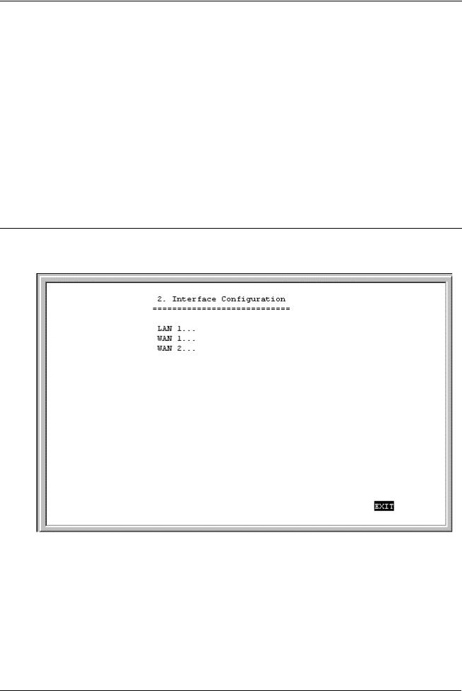
Console Program Main Menu
The Main Menu is shown below.
15

DI-1162/DI-1162M Remote Access Router
As mentioned earlier, your first endeavor should be to increase the automatic timeout. Enter the System Information to do this. You will see this screen:
System Information
This menu contains administrative and system-related information:
The above parameters are described as follows:
16
DI-1162/DI-1162M Remote Access Router
♦System Description – This is a non-changeable, short description of the product.
♦System Object ID – This is the enterprise-specific MIB Object ID indicating this type of router.
♦System Up Time – Shows how long the router has been running since the last power off or reset.
♦System Contact – Enter the name of the department or individual responsible for maintaining the router.
♦System Name – Give the router a descriptive name for identification purposes.
♦System Location – Enter the physical location of the router.
♦Console/Telnet Display Timeout in Minutes – This is a security measure to automatically logoff from the console menu after a given idle time. Enter a timeout time between 0 and 90 minutes. Zero specifies no timeout.
♦System MAC Address –The physical address of this router.
♦External MAC Address – The physical address of the external LAN add-in module, if present.
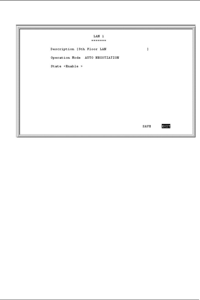
Interface Configuration
Under Interface Configuration in the main menu is the following Interface Configuration screen, used to configure the interfaces for the LAN(s) and two WANs:
17
DI-1162/DI-1162M Remote Access Router
LAN
The parameters are described below:
♦Description – This is a user-defined, 32-character identifier used to name the LAN.
♦Operation Mode – The LAN port is automatically set to auto-negotiation. When connected to another LAN port, 10/100 Fast Ethernet will configure this port to match the settings of the other LAN port. If the other port also implements 10/100 Fast Ethernet, the two ports will auto-negotiate the best possible settings achievable by both ports.
♦State – This is a toggle, to Disable or Enable the LAN interface.
18
DI-1162/DI-1162M Remote Access Router
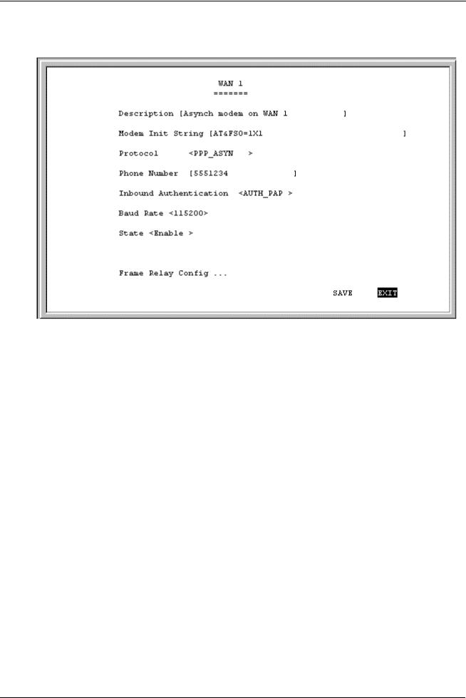
WAN
The parameters are described below:
♦Description – This is a user-defined, 32-character identifier used to name the WAN.
♦Modem Init String – This parameter is valid only for asynchronous connections. It is a user input AT command string to initialize a modem or ISDN TA attached to the WAN interface. Please refer to your WAN device’s handbook for more information about using initialization command strings.
The default setting is for Hayes-compatible asynchronous modems and is AT&FS0=1X1, where:
AT– |
The mandatory first two characters of an AT command string. |
&F– |
Initializes the modem to its default settings. |
S0=1– |
Sets the modem to auto-answer. |
X1 – |
Displays the established connection speed to the dial-in user (e.g. Connection established at 56.6 |
|
kps). |
♦Protocol – This is a protocol used to encapsulate IP messages over synchronous and asynchronous serial links. The device being connected to must be using the same protocol for a connection to succeed. The five protocols are described:
1.CISCO_HDLC – This is a serial line encapsulation method for transmitting datagrams over synchronous serial point-to-point links.
2.SLIP – Serial Line Internet Protocol. A serial line encapsulation method for transmitting datagrams over asynchronous serial point-to-point links. If linking the router to a computer, each end must know the other’s IP address.
3.PPP_SYN – This serial line encapsulation provides a method for transmitting datagrams over synchronous serial point-to-point links. Unlike the SLIP protocol, PPP can determine the IP address configuration automatically.
19

DI-1162/DI-1162M Remote Access Router
4.PPP_ASYN – This serial line encapsulation provides a method for transmitting datagrams over asynchronous serial point-to-point links. Unlike the SLIP protocol, PPP can determine the IP address configuration automatically.
5.FRAME_RELAY – This serial line encapsulation provides a method for high speed transmission of datagrams over dedicated lines. We currently only support PVC.
♦Phone Number – This is only a reference field, used to contain your line’s phone number when using an asynchronous dial-in modem.
♦Inbound Authentication – This defines the authorization protocol that will be used when accepting a dial-in connection. The choices are Password Authentication Protocol [AUTH_PAP], Challenge Handshake Authentication Protocol [AUTH_CHAP] or None. AUTH_PAP and AUTH_CHAP do not provide a screen for users to manually enter their Username and Password – instead, this data must be entered into the dialing software before placing the call. Make sure the device dialing in is using the same protocol as defined here. The None setting may be used when you do not wish dial-in users or networks to identify themselves or be subject to security.
♦Baud Rate – This parameter must be set to configure the communication speed for asynchronous communication devices (modems). Please refer to the communication device’s handbook to get the proper setting.
Available synchronous communication device speeds are: 9600, 19200, 38400, 64K, 128K, 256K, 512K, 1M, 1.544M, and 2M baud. Available asynchronous communication device speeds are: 9600, 19200, 38400, 57600, and 115200.
For synchronous connections, the router will automatically match the clock speed of the device being connected.
♦State – This is used to Disable or Enable this interface.
♦Frame Relay Config . . . – Highlight this item and hit <Enter> if FRAME_RELAY is selected as the Protocol above and then complete the WAN Frame Relay configuration settings on the screens described below.
20
DI-1162/DI-1162M Remote Access Router
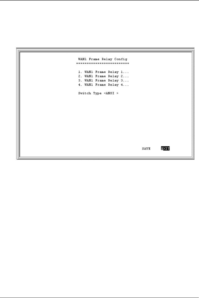
WAN Frame Relay Config
This screen allows you to specify which WAN 1 or WAN 2 Frame Relay is to be configured by highlighting the desired entry below and then hitting <Enter>. Next, enter a Data Link Connection Identifier (DLCI) between 16 and 991 and Enable it in the State field on the following screen. Additionally, you must choose the appropriate Switch Type on the WAN Frame Relay Config screen below to complete the WAN Frame Relay configuration.
The parameter is described below:
♦Switch Type – This allows you to choose Local Management Interface (LMI) specification. Currently, we support ANSI T1.617 Annex D and ITU Q.933 Annex A specifications. This switch type must be configured to match your Frame Relay subscription. Once a change has been made, the router must be rebooted.
21
DI-1162/DI-1162M Remote Access Router
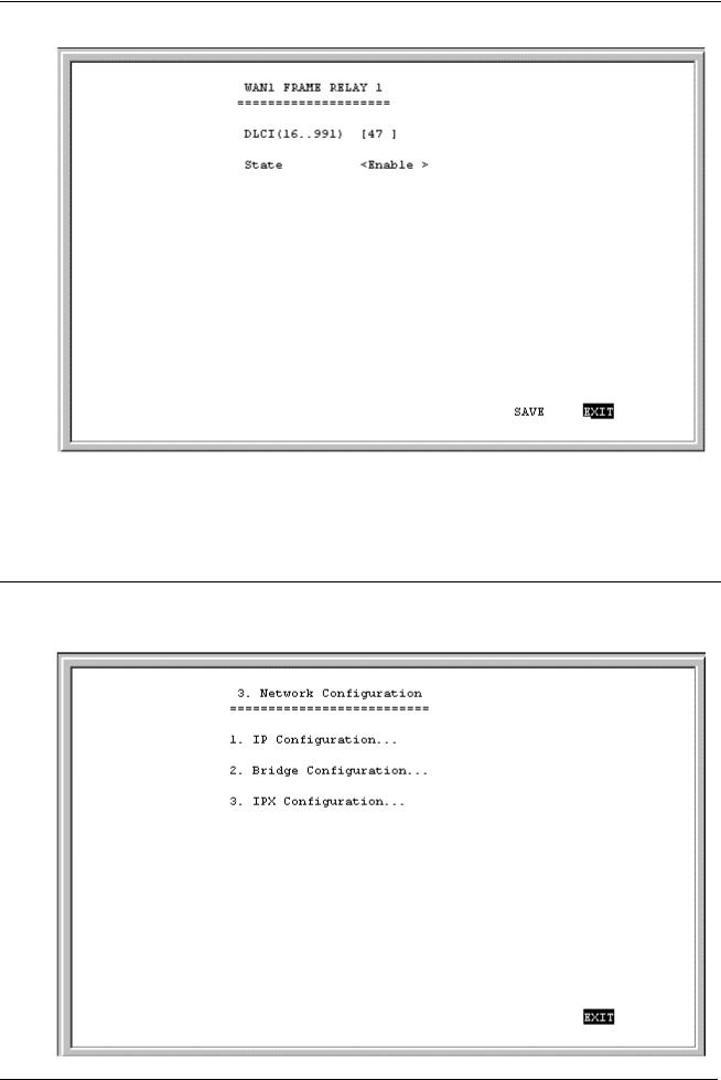
The parameters are described below:
♦DLCI(16. .991) – This Data Link Connection Identifier is used to match your Frame Relay subscription..
♦State – This is a toggle, to Disable or Enable the WAN interface.
Network Configuration
There are three items on the Network Configuration menu: (Bridge Configuration and IPX Configuration appear on DI-1162M only):
22
DI-1162/DI-1162M Remote Access Router
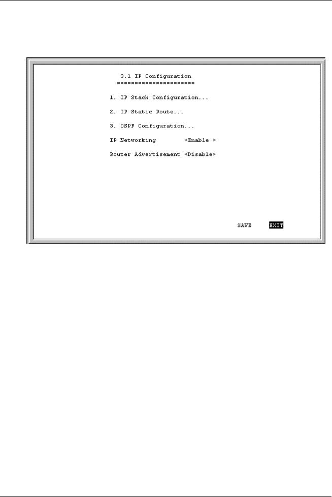
IP Configuration
IP networking and router advertisement are enabled on the IP Configuration screen:
The parameters are described below:
♦IP Networking – The IP Networking function can toggle to connect/disconnect this router from the entire IP network. When IP Networking is disabled, all routing functions are stopped. The only IP Address the router will act on is it’s own, via Telnet for example.
♦Router Advertisement – When this option is enabled, the router will periodically send out ICMP packets that announce itself on the network. These ICMP packets are utilized by the Windows 98 or later operating system, which will automatically update the default gateway setting on the computer in which it is installed.
IP Stack Configuration
The network interface IP address, mask and protocols are specified in the IP Stack Configuration submenus. Choose the desired interface from the IP Stack Configuration menu below:
23
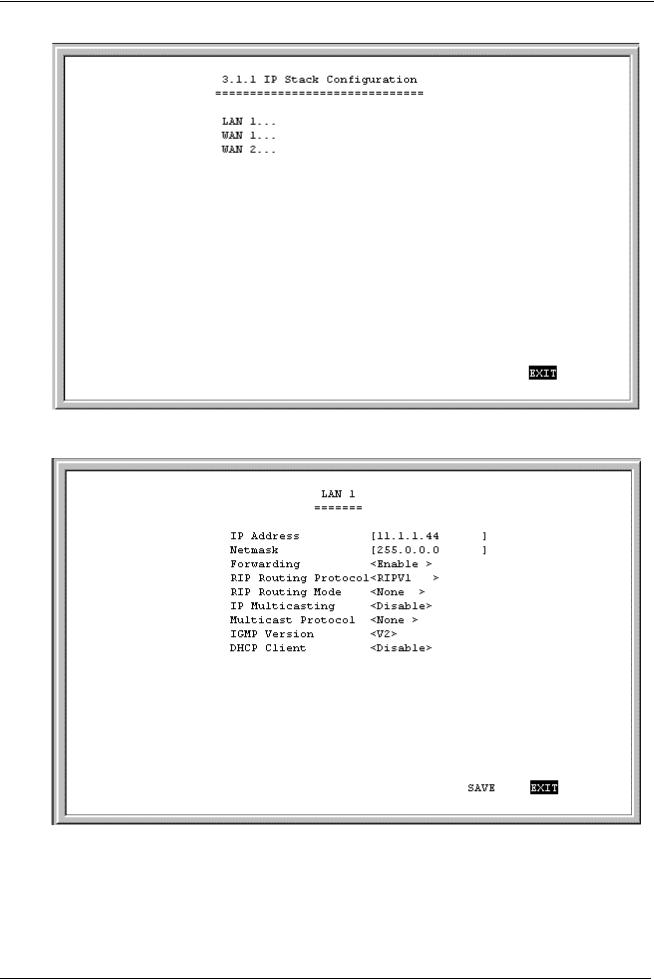
DI-1162/DI-1162M Remote Access Router
Below, the submenus for both the LAN and WAN interfaces are shown.
24
Loading...