


FXMQ07PVJU
DAIKIN FXMQ07PVJU, FXMQ18PVJU, FXMQ36PVJU, FXMQ09PVJU, FXMQ24PVJU INSTALLATION MANUAL
...
INSTALLATION MANUAL
SYSTEM Inverter Air Conditioners
English
Français
MODELS
Ceiling-mounted Duct type
FXMQ07PVJU FXMQ18PVJU FXMQ36PVJU
FXMQ09PVJU FXMQ24PVJU FXMQ48PVJU
FXMQ12PVJU FXMQ30PVJU
READ THESE INSTRUCTIONS CAREFULLY BEFORE INSTALLATION.
KEEP THIS MANUAL IN A HANDY PLACE FOR FUTURE REFERENCE.
LIRE SOIGNEUSEMENT CES INSTRUCTIONS AVANT L’INSTALLATION.
CONSERVER CE MANUEL A PORTEE DE MAIN POUR REFERENCE ULTERIEURE.
LEA CUIDADOSAMENTE ESTAS INSTRUCCIONES ANTES DE INSTALAR.
GUARDE ESTE MANUAL EN UN LUGAR A MANO PARA LEER EN CASO DE TENER ALGUNA
DUDA.
Español
VRV SYSTEM Inverter Air Conditioners
Installation manual
CONTENTS
1. SAFETY CONSIDERATIONS..........................................1
2. BEFORE INSTALLATION ................................................ 3
3. SELECTING INSTALLATION SITE..................................4
4. PREPARATIONS BEFORE INSTALLATION ....................5
5. INDOOR UNIT INSTALLATION ....................................... 6
6. REFRIGERANT PIPING WORK...................................... 7
7. DRAIN PIPING WORK .................................................... 8
8. DUCT WORK................................................................. 10
9. ELECTRIC WIRING WORK .......................................... 11
10. WIRING EXAMPLE AND HOW TO SET
THE REMOTE CONTROLLER...................................... 11
11. FIELD SETTING............................................................14
12. TEST OPERATION........................................................ 16
1. SAFETY CONSIDERATIONS
Read these SAFETY CONSIDERATIONS for Installation
carefully before installing air conditioning equipment. After completing the installation, make sure that the unit operates properly during the startup operation.
Instruct the customer on how to operate and maintain the unit.
Inform customers that they should store this Installation Manual
with the Operation Manual for future reference.
Always use a licensed installer or contractor to install this product. Improper installation can result in water or refrigerant leakage, electrical shock, fire, or explosion.
Meanings of DANGER, WARNING, CAUTION, and NOTE
Symbols:
DANGER................. Indicates an imminently hazardous
situation which, if not avoided, will
result in death or serious injury.
WARNING...............Indicates a potentially hazardous situ-
ation which, if not avoided, could result
in death or serious injury.
CAUTION................ Indicates a potentially hazardous situ-
ation which, if not avoided, may result
in minor or moderate injury. It may also
be used to alert against unsafe practices.
NOTE...................... Indicates situations that may result in
equipment or property-damage accidents only.
DANGER
• Refrigerant gas is heavier than air and replaces oxygen.
A massive leak can lead to oxygen depletion, especially
in basements, and an asphyxiation hazard could occur
leading to serious injury or death.
• Do not ground units to water pipes, gas pipes, telephone
wires, or lightning rods as incomplete grounding can
cause a severe shock hazard resulting in severe injury or
death. Additionally, grounding to gas pipes could cause a
gas leak and potential explosion causing severe injury or
death.
• If refrigerant gas leaks during installation, ventilate the
area immediately. Refrigerant gas may produce toxic gas
if it comes in contact with fire. Exposure to this gas could
cause severe injury or death.
• After completing the installation work, check that the refrigerant gas does not leak throughout the system.
• Do not install unit in an area where flammable materials
are present due to risk of explosions that can cause serious injury or death.
• Safely dispose all packing and transportation materials
in accordance with federal/state/local laws or ordinances. Packing materials such as nails and other metal or
wood parts, including plastic packing materials used for
transportation may cause injuries or death by suffocation.
WARNING
• Only qualified personnel must carry out the installation
work. Installation must be done in accordance with this
installation manual. Improper installation may result in
water leakage, electric shock, or fire.
• When installing the unit in a small room, take measures
to keep the refrigerant concentration from exceeding allowable safety limits. Excessive refrigerant leaks, in the
event of an accident in a closed ambient space, can lead
to oxygen deficiency.
• Use only specified accessories and parts for installation
work. Failure to use specified parts may result in water
leakage, electric shocks, fire, or the unit falling.
• Install the air conditioner on a foundation strong enough
that it can withstand the weight of the unit. A foundation
of insufficient strength may result in the unit falling and
causing injuries.
• Take into account strong winds, typhoons, or earthquakes when installing. Improper installation may result
in the unit falling and causing accidents.
• Make sure that a separate power supply circuit is provided for this unit and that all electrical work is carried out
by qualified personnel according to local state, and national regulations. An insufficient power supply capacity
or improper electrical construction may lead to electric
shocks or fire.
• Make sure that all wiring is secured, that specified wires
are used, and that no external forces act on the terminal
connections or wires. Improper connections or installation may result in fire.
• When wiring, position the wires so that the terminal box
lid can be securely fastened. Improper positioning of the
terminal box lid may result in electric shocks, fire, or the
terminals overheating.
English 1
• Before touching electrical parts, turn off the unit.
• Be sure to install a ground fault circuit interrupter if one
is not already available. This helps prevent electrical
shocks or fire.
• Securely fasten the outside unit terminal cover (panel). If
the terminal cover/panel is not installed properly, dust or
water may enter the outside unit causing fire or electric
shock.
• When installing or relocating the system, keep the refrigerant circuit free from substances other than the specified refrigerant (R-410A) such as air. Any presence of air
or other foreign substance in the refrigerant circuit can
cause an abnormal pressure rise or rupture, resulting in
injury.
• Do not change the setting of the protection devices. If the
pressure switch, thermal switch, or other protection device is shorted and operated forcibly, or parts other than
those specified by Daikin are used, fire or explosion may
occur.
CAUTION
• Do not touch the switch with wet fingers. Touching a
switch with wet fingers can cause electric shock.
• Do not allow children to play on or around the unit to prevent injury.
• Do not touch the refrigerant pipes during and immediately after operation as the refrigerant pipes may be hot or
cold, depending on the condition of the refrigerant flowing through the refrigerant piping, compressor, and other
refrigerant cycle parts. Your hands may suffer burns or
frostbite if you touch the refrigerant pipes. To avoid injury, give the pipes time to return to normal temperature or,
if you must touch them, be sure to wear proper gloves.
• Heat exchanger fins are sharp enough to cut.
To avoid injury wear glove or cover the fins when working
around them.
• Install drain piping to proper drainage. Improper drain
piping may result in water leakage and property damage.
• Insulate piping to prevent condensation.
• Be careful when transporting the product.
• Do not turn off the power immediately after stopping operation. Always wait for at least 5 minutes before turning
off the power. Otherwise, water leakage may occur.
• Do not use a charging cylinder. Using a charging cylinder
may cause the refrigerant to deteriorate.
• Refrigerant R-410A in the system must be kept clean, dry,
and tight.
(a) Clean and Dry -- Foreign materials (including mineral
oils such as SUNISO oil or moisture) should be prevented from getting into the system.
(b) Tight -- R-410A does not contain any chlorine, does
not destroy the ozone layer, and does not reduce the
earth’s protection again harmful ultraviolet radiation.
R-410A can contribute to the greenhouse effect if it is
released. Therefore take proper measures to check
for the tightness of the refrigerant piping installation.
Read the chapter Refrigerant Piping and follow the
procedures.
• Since R-410A is a blend, the required additional refrigerant must be charged in its liquid state. If the refrigerant is
charged in a state of gas, its composition can change and
the system will not work properly.
• The indoor unit is for R-410A. See the catalog for indoor
models that can be connected. Normal operation is not
possible when connected to other units.
• Indoor units are for indoor installation only. Outdoor
units can be installed either outdoors or indoors.
• Do not install the air conditioner in the following locations:
(a) Where a mineral oil mist or oil spray or vapor is pro-
duced, for example, in a kitchen.
Plastic parts may deteriorate and fall off or result in
water leakage.
(b) Where corrosive gas, such as sulfurous acid gas, is
produced.
Corroding copper pipes or soldered parts may result
in refrigerant leakage.
(c) Near machinery emitting electromagnetic waves.
Electromagnetic waves may disturb the operation of
the control system and cause the unit to malfunction.
(d) Where flammable gas may leak, where there is car-
bon fiber, or ignitable dust suspension in the air, or
where volatile flammables such as thinner or gasoline are handled. Operating the unit in such conditions can cause a fire.
• Take adequate measures to prevent the outside unit from
being used as a shelter by small animals. Small animals
making contact with electrical parts can cause malfunctions, smoke, or fire. Instruct the customer to keep the
area around the unit clean.
NOTE
• Install the power supply and control wires for the indoor
and outdoor units at least 3.5 feet away from televisions
or radios to prevent image interference or noise. Depending on the radio waves, a distance of 3.5 feet may not be
sufficient to eliminate the noise.
• Dismantling the unit, treatment of the refrigerant, oil and
additional parts must be done in accordance with the relevant local, state, and national regulations.
• Do not use the following tools that are used with conventional refrigerants: gauge manifold, charge hose, gas
leak detector, reverse flow check valve, refrigerant
charge base, vacuum gauge, or refrigerant recovery
equipment.
• If the conventional refrigerant and refrigerator oil are
mixed in R-410A, the refrigerant may deteriorate.
• This air conditioner is an appliance that should not be accessible to the general public.
• The wall thickness of field-installed pipes should be selected in accordance with the relevant local, state, and
national regulations.
2 English
2. BEFORE INSTALLATION
•
When moving the unit while removing it from the carton
box, be sure to lift it by holding on to the four lifting lugs
without exerting any pressure on other parts, especially,
the refrigerant piping, drain piping, flanges and other
resin parts
• Be sure to check the type of R410A refrigerant to be used
before installing the unit. (Using an incorrect refrigerant will
prevent normal operation of the unit.)
• The accessories needed for installation must be retained in
your custody until the installation work is completed. Do not
discard them!
• Decide upon a line of transport.
• Leave the unit inside its packaging while moving, until reaching the installation site. Where unpacking is unavoidable, use
a sling of soft material or protective plates together with a
rope when lifting, to avoid damage or scratches to the unit.
• When moving the unit or affter opening, hold the unit by the
hanger brackets (× 4). Do not apply force to the refrigerant
piping, drain piping, flanges or plastic parts.
• For the installation of outdoor unit, refer to the installation
manual attached to the outdoor unit.
• Do not install or operate the unit in rooms mentioned below.
• Laden with mineral oil, or filled with oil vapor or spray
like in kitchens. (Plastic parts may deteriorate which
could eventually cause the unit to fall out of place, or
could lead to leaks.)
• Where corrosive gas like sulfurous gas exists. (Copper tubing and brazed spots may corrode which could
eventually lead to refrigerant leaks.)
• Where exposed to combustible gases and where volatile flammable gas like thinner or gasoline is used.
(Gas in the vicinity of the unit could ignite.)
• Where machines can generate electromagnetic
waves. (Control system may malfunction.)
• Where the air contains high levels of salt such as that
near the ocean and where voltage fluctuates greatly
such as that in factories.
Also in vehicles or vessels.
This unit, both indoor and outdoor, is suitable for installation in a
•
commercial and light industrial environment.
If installed as a household appliance it could cause electromagnetic interference.
2-1 PRECAUTIONS
• Be sure to read this manual before installing the indoor unit.
• Entrust installation to the place of purchase or a qualified serviceman. Improper installation could lead to leaks and, in
worse cases, electric shock of fire.
• Use only parts provided with the unit or parts satisfying
required specifications. Unspecified parts could cause the
unit to fall out of place, or could lead to leaks and, in worse
cases, electric shock or fire.
• Be sure to mount an air filter (part to be procured in the field)
in the suction air passage in order to prevent water leaking,
etc.
.
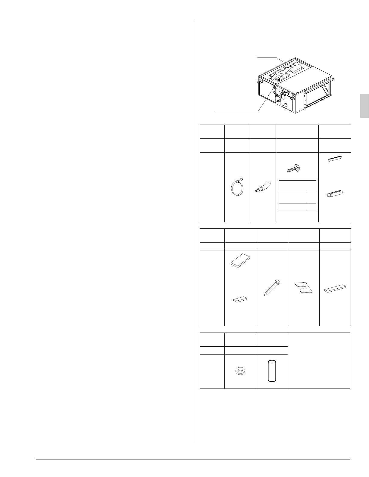
[PRECAUTION]
The accessories are required for the installation of the air conditioner. Be sure to keep them until the installation work is completed.
(1) - (12)
Operation manual
Installation manual
Name
Quantity 1 pc. 1 pc.
Shape
Name Sealing pad Clamp (8)
Quantity – 11 pcs. 4 pcs. 2 pcs.
Shape
Name Washer (11)
Quantity 8 pcs. 2 pcs.
Shape
Metal
clamp (1)
1 pc.
Large
(Dark gray) (6)
2 pcs.
Middle
(Dark gray) (7)
Drain
hose (2)
Insulation
tube (12)
Screws for duct
flanges (3)
As described in
table below
M5×5/8
07 • 09 •
12 type
18 • 24 •
30 type
36 • 48 type
Washer fix-
ing plate (9)
(Other)
• Operation manual
• Installation manual
Fig. 1
Insulation for
for liquid pipe
6
18
26
for gas pipe
Wire sealing
material (10)
fitting
1 each
Thin
(4)
Thick
(5)
Small
(Gray)
2-2 ACCESSORIES
Check that the following accessories are provided and that each
accessory is correct in amount.
Refer to the Fig. 1 of this sheet.
English 3
2-3 OPTIONAL ACCESSORIES
• These is one type of remote controller: wired.
NOTE
• If you wish to use a remote controller that is different from the
above, select a suitable remote controller after consulting
catalogs and technical materials.
FOR THE FOLLOWING ITEMS, TAKE SPECIAL
CARE DURING CONSTRUCTION AND CHECK
AFTER INSTALLATION IS FINISHED.
a. Items to be checked after completion of work
Items to be checked
Are the indoor and outdoor
unit fixed firmly?
Was the installation of the
outdoor unit completed?
Is the gas leak test
finished?
Is the unit fully insulated?
(Refrigerant piping, drain
piping, and duct)
Dose drainage flow
smoothly?
Does the power supply voltage conform to the indication on the name plate?
Are wiring and piping
correct?
Is the air conditioner properly grounded?
Is wiring size according to
specifications?
Is something blocking the
air outlet or inlet of either
the indoor or outdoor units?
Did you set the external
static pressure?
Are refrigerant piping length
and additional refrigerant
charge noted down?
Did you check that no wiring
connection screws were
loose?
If not properly done, what is
likely to occur.
The units may drop, vibrate
or make noise.
The unit may malfunction or
the components burn out.
No cooling or heating.
Condensate water may drip.
Condensate water may drip.
The unit may malfunction or
the components burn out.
The unit may malfunction or
the components burn out.
Dangerous in case of current leakage.
The unit may malfunction or
the components burn out.
No cooling or heating.
No cooling or heating.
The refrigerant charge in
the system is not clear.
Electric shock or fire.
Also review the “SAFETY CONSIDERATIONS”.
Check
b. Items to be checked at time of delivery
Items to be checked Check
Are you sure the control box lid, air filter, air inlet grille, and
air outlet grille are mounted?
Did you explain about operations while showing the opera-
tion manual to your customer?
Did you deliver the operation manual along with the instal-
lation manual to the customer?
Did you explain the customer the handling and cleaning
methods of the field supplies (e.g., the air filter, air inlet
grilles, and air outlet grille)?
Did you deliver instruction manual, if any, for the field supplies to the customer?
c. Points for explanation about operations
The items with WARNING and CAUTION marks in the operation
manual are the items pertaining to possibilities for bodily injury and
material damage in addition to the general usage of
the product. Accordingly, it is necessary that you make a full explanation about the described contents and also ask your customers to
read the operation manual.
2-4 NOTE TO INSTALLER
• Be sure to instruct customers how to properly operate the
unit (especially cleaning filters, operating different functions,
and adjusting the temperature) by having them carry out
operations themselves while looking at the manual.
3. SELECTING INSTALLATION SITE
〈Hold the hanging brackets in the case of moving the
indoor and outdoor units at the time of and after opening
the packages. Do not impose undue force on other parts,
such as the refrigerant piping, drain piping, or flanges, in
particular.〉
〈Add heat insulation material to the indoor unit if the temperature above the ceiling is likely to exceed 86°F and a relative humidity of 80%.〉
Make sure that the insulation material is made of glass wool
〈
or polyethylene foam, has a minimum thickness of 3/8 in.,
and can be accommodated in the opening on the ceiling.
(1) Select an installation site where the following conditions are
fulfilled and that meets with your customer’s approval.
• A place where cool (warm) air is delivered to the entire
room.
• Where nothing blocks the air passage.
• Where condensate can be properly drained.
• If supporting structural members are not strong enough
to take the unit’s weight, the unit could fall out of place
and cause serious injury.
• Where the false ceiling is not noticeably on an incline.
• Where there is no risk of flammable gas leakage.
• Where sufficient clearance for maintenance and service
can be ensured. (Refer to Fig. 2-1)
• Where piping between indoor and outdoor units is possible within the allowable limit. (Refer to the installation
manual of the outdoor unit.)
〉
4 English
CAUTION
• Install the indoor and outdoor units, power supply wiring and
connecting wires at least 3.3 ft away from televisions or radios
in order to prevent image interference or noise.
(Depending on the radio waves, a distance of 3.3 ft may not
be sufficient enough to eliminate the noise.)
• In the case of the installation of a wireless remote controller, the
transmission distance of the wireless remote controller may be
shortened if the room has a fluorescent light of electronic lighting type (i.e., an inverter or rapid-start fluorescent light).
Keep the distance between the receiver and the fluorescent
light as far as possible.
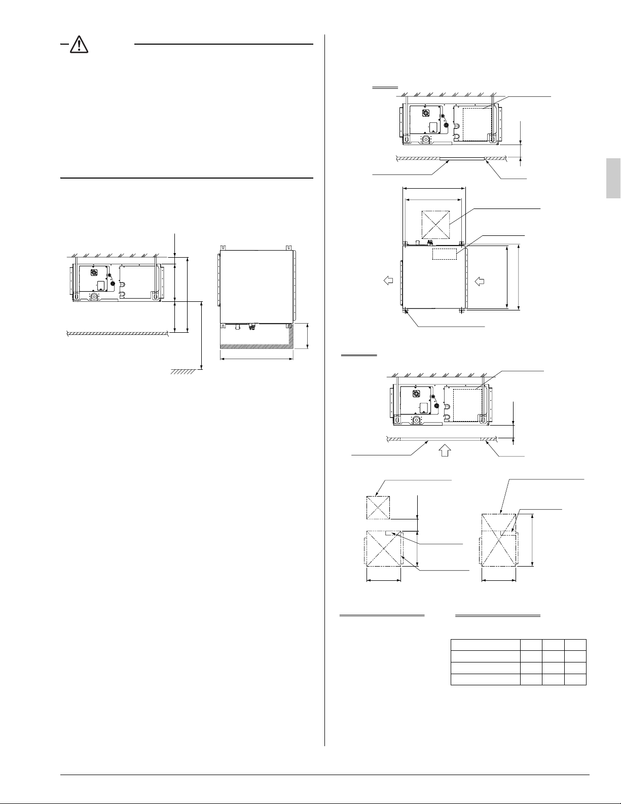
(2) Use hanging bolts to install the indoor unit. Check that the
place of installation withstands the weight of the indoor unit.
Secure the hanging bolts with proper beams if necessary.
(length: in.)
Min. 1
3. Inspection hatch 3 for the lower part of the product
and the lower part of the control box (see axial direction view A-2). (Refer to Fig. 2-3)
Case 1
Inspection hatch
24-13/16
(Hanging bolt pitch)
28
Inspection hatch 1
(17-3/4×17-3/4)
Control box
(length: in.)
Control box
*H3=Min. 12
Ceiling
*H1=12
*H2=Min. 25
Ceiling
• The H1 dimension indicates the
height of the product.
• Determine the H2 dimension by
maintaining a downward slope of
at least 1/100 as specified in
“7. DRAIN PIPING WORK”.
Min. 12
Floor surface
Min. 99
(If no ceiling board is provided.)
Min. 28 (service space)
[Required installation place]
The dimensions indicate the
minimum required space of
installation.
Fig. 2-1
Min. 18
4. PREPARATIONS BEFORE INSTALLATION
(1) Check the positional relationship between the ceiling open-
ing hole and the hanging bolt of the unit.
• For the maintenance, inspection, and other servicing
purposes of the control box and drain pump, prepare one
of the following service spaces.
1. Inspection hatch 1 (17-3/4 × 17-3/4) for the control
box and a minimum space of 12 in. for the lower part
of the product. (Refer to Fig. 2-2)
2. Inspection hatch 1 (17-3/4 × 17-3/4) for the control
box and inspection hatch 2 for the lower part of the
product (see axial direction view A-1). (Refer to Fig.
2-3)
Air outlet
Case 2, 3
Inspection hatch
Axial direction view A-1 Axial direction view A-2
Bottom of unit
Air inlet
Hanging bolt (× 4)
Inspection hatch
(Ceiling opening)
A
Inspection hatch 1
(17-3/4×17-3/4)
Min. 8B
Control box
Inspection
28 28
hatch 2
(Same as the
indoor unit
size or more)
B
C
(Hanging bolt pitch)
Control box
*H3=Min. 3/4
Ceiling
Inspection hatch 3
(Same as the indoor
unit size +12 or more)
Control box
Min. D=B+12
Fig. 2-2
• Determine the H3
dimension by maintaining a
downward slope of at least
1/100 as specified in
“7. DRAIN PIPING WORK”.
07 • 09 • 12 type 22
18 • 24 • 30 type
36 • 48 type
Fig. 2-3
Model B C D
23-1/8
40
40-7/8
56
56-5/8
(length: in.)
34
52
68
English 5
 Loading...