


4524GT
Table of contents
 Loading...
Avaya 4524GT, 4524GT-PWR, 4526FX, 4526GTX, 4526GTX-PWR Configuration Manual
...
Configuration — System
Avaya Ethernet Routing Switch 4500
Series
NN47205-500, 07.01
5.5
April 2011

© 2011 Avaya Inc.
All Rights Reserved.
Notice
While reasonable efforts have been made to ensure that the
information in this document is complete and accurate at the time of
printing,
right to make changes and corrections to the information in this
document without the obligation to notify any person or organization of
such changes.
Documentation disclaimer
“Documentation” means information published by Avaya in varying
mediums which may include product information, operating instructions
and performance specifications that Avaya generally makes available
to users of its products. Documentation does not include marketing
materials. Avaya shall not be responsible for any modifications,
additions, or deletions to the original published version of
documentation unless such modifications, additions, or deletions were
performed by Avaya. End User agrees to indemnify and hold harmless
Avaya, Avaya's agents, servants and employees against all claims,
lawsuits, demands and judgments arising out of, or in connection with,
subsequent modifications, additions or deletions to this documentation,
to the extent made by End User.
Link disclaimer
Avaya is not responsible for the contents or reliability of any linked Web
sites referenced within this site or documentation provided by Avaya.
Avaya is not responsible for the accuracy of any information, statement
or content provided on these sites and does not necessarily endorse
the products, services, or information described or offered within them.
Avaya does not guarantee that these links will work all the time and has
no control over the availability of the linked pages.
Warranty
Avaya provides a limited warranty on its Hardware and Software
(“Product(s)”). Refer to your sales agreement to establish the terms of
the limited warranty. In addition, Avaya’s standard warranty language,
as well as information regarding support for this Product while under
warranty is available to Avaya customers and other parties through the
Avaya Support Web site:
you acquired
of the United States and Canada, the warranty is provided to you by
said Avaya reseller and not by Avaya.
Licenses
THE SOFTWARE LICENSE TERMS AVAILABLE ON THE AVAYA
WEBSITE,
APPLICABLE T
INSTALLS AVAYA SOFTWARE, PURCHASED FROM AVAYA INC.,
ANY AVAYA AFFILIATE, OR AN AUTHORIZED AVAYA RESELLER
(AS APPLICABLE) UNDER A COMMERCIAL AGREEMENT WITH
AVAYA OR AN AUTHORIZED AVAYA RESELLER. UNLESS
OTHERWISE AGREED TO BY AVAYA IN WRITING, AVAYA DOES
NOT EXTEND THIS LICENSE IF THE SOFTWARE WAS OBTAINED
FROM ANYONE OTHER THAN AVAYA, AN AVAYA AFFILIATE OR AN
AVAYA AUTHORIZED RESELLER; AVAYA RESERVES THE RIGHT
TO TAKE LEGAL ACTION AGAINST YOU AND ANYONE ELSE
USING OR SELLING THE SOFTWARE WITHOUT A LICENSE. BY
INSTALLING, DOWNLOADING OR USING THE SOFTWARE, OR
AUTHORIZING OTHERS TO DO SO, YOU, ON BEHALF OF
YOURSELF AND THE ENTITY FOR WHOM YOU ARE INSTALLING,
DOWNLOADING OR USING THE SOFTWARE (HEREINAFTER
REFERRED TO INTERCHANGEABLY AS “YOU” AND “END USER”),
AGREE TO THESE TERMS AND CONDITIONS AND CREATE A
BINDING CONTRACT BETWEEN YOU AND AVAYA INC. OR THE
APPLICABLE AVAYA AFFILIATE ( “AVAYA”).
Avaya assumes no liability for any errors. Avaya reserves the
http://support.avaya.com. Please note that if
the Product(s) from an authorized Avaya reseller outside
HTTP://SUPPORT.AVAYA.COM/LICENSEINFO/ ARE
O ANYONE WHO DOWNLOADS, USES AND/OR
Copyright
Except where expressly stated otherwise, no use should be made of
materials on this site, the Documentation, Software, or Hardware
provided by
Product provided by Avaya including the selection, arrangement and
design of the content is owned either by Avaya or its licensors and is
protected by copyright and other intellectual property laws including the
sui generis rights relating to the protection of databases. You may not
modify, copy, reproduce, republish, upload, post, transmit or distribute
in any way any content, in whole or in part, including any code and
software unless expressly authorized by Avaya. Unauthorized
reproduction, transmission, dissemination, storage, and or use without
the express written consent of Avaya can be a criminal, as well as a
civil offense under the applicable law.
Third-party components
Certain software programs or portions thereof included in the Product
may contain software distributed under third party agreements (“Third
Party Components”), which may contain terms that expand or limit
rights to use certain portions of the Product (“Third Party Terms”).
Information regarding distributed Linux OS source code (for those
Products that have distributed the Linux OS source code), and
identifying the copyright holders of the Third Party Components and the
Third Party Terms that apply to them is available on the Avaya Support
Web site:
Trademarks
The trademarks, logos and service marks (
site, the Documentation and Product(s) provided by Avaya are the
registered or unregistered Marks of Avaya, its affiliates, or other third
parties. Users are not permitted to use such Marks without prior written
consent from Avaya or such third party which may own the Mark.
Nothing contained in this site, the Documentation and Product(s)
should be construed as granting, by implication, estoppel, or otherwise,
any license or right in and to the Marks without the express written
permission of Avaya or the applicable third party.
Avaya is a registered trademark of Avaya Inc.
All non-Avaya trademarks are the property of their respective owners,
and “Linux” is a registered trademark of Linus Torvalds.
Downloading Documentation
For the most current versions of Documentation, see the Avaya
Support Web site:
Contact A
Avaya provides a telephone number for you to use to report problems
or to ask questions about your Product. The support telephone number
is 1-800-242-2121 in the United States. For additional support
telephone numbers, see the Avaya Web site:
Avaya. All content on this site, the documentation and the
http://support.avaya.com/Copyright.
“Marks”) displayed in this
http://support.avaya.com.
vaya Support
http://support.avaya.com.
2 Configuration — System April 201
1

Contents
Chapter 1: New in this release................................................................................................11
Features..........................................................................................................................................................11
802.1AB customization...........................................................................................................................11
802.1AB integration................................................................................................................................12
New 802.1AB default parameters...........................................................................................................12
Chapter 2: Introduction...........................................................................................................13
ACLI command modes....................................................................................................................................13
Chapter 3: System configuration fundamentals...................................................................15
Hardware features...........................................................................................................................................15
Cooling fans............................................................................................................................................16
Redundant power supply........................................................................................................................16
DC-DC Converter Module......................................................................................................................17
Stacking capabilities........................................................................................................................................17
Auto Unit Replacement...................................................................................................................................18
AUR function..........................................................................................................................................19
Agent Auto Unit Replacement................................................................................................................26
Diagnostics AUR (DAUR).......................................................................................................................27
Stack Forced Mode.........................................................................................................................................29
IPv6 management...........................................................................................................................................30
The IPv6 header.....................................................................................................................................31
IPv6 addresses.......................................................................................................................................31
Address formats.....................................................................................................................................32
IPv6 extension headers..........................................................................................................................32
Comparison of IPv4 and IPv6.................................................................................................................33
ICMPv6...................................................................................................................................................34
Neighbor discovery.................................................................................................................................34
Router discovery.....................................................................................................................................38
Path MTU discovery...............................................................................................................................38
Flash memory storage....................................................................................................................................39
Switch software image storage...............................................................................................................39
Configuration parameter storage............................................................................................................39
Policy-enabled networking..............................................................................................................................40
Power over Ethernet.......................................................................................................................................40
Port mirroring..................................................................................................................................................41
Auto-MDI/X......................................................................................................................................................41
Auto-polarity....................................................................................................................................................41
Time Domain Reflectometer............................................................................................................................41
Autosensing and autonegotiation....................................................................................................................42
Custom Autonegotiation Advertisements........................................................................................................42
Configuring CANA using ACLI................................................................................................................43
Viewing current autonegotiation advertisements....................................................................................43
Viewing hardware capabilities................................................................................................................44
Setting default advertisements...............................................................................................................44
Silencing advertisements........................................................................................................................44
ASCII configuration file....................................................................................................................................45
Sample ASCII configuration file..............................................................................................................45
Configuration — System April 2011 3

ASCII Download Enhancements............................................................................................................47
Backup configuration file.................................................................................................................................51
Displaying unit uptime.....................................................................................................................................52
Port naming.....................................................................................................................................................52
Port error summary.........................................................................................................................................52
IP address for each unit in a stack..................................................................................................................52
mode....................................................................................................................................................52
BootP
DHCP client.....................................................................................................................................................53
Web Quick Start..............................................................................................................................................53
Simple Network Time Protocol........................................................................................................................54
Ping enhancement..........................................................................................................................................55
New unit Quick configuration..........................................................................................................................55
Updating switch software................................................................................................................................55
LED activity during software download...................................................................................................56
Asset ID string configuration...........................................................................................................................56
Agent and diagnostic software status display.................................................................................................56
Avaya Energy Saver........................................................................................................................................56
Chapter 4: Power over Ethernet.............................................................................................59
PoE overview..................................................................................................................................................59
Port power priority...........................................................................................................................................60
Viewing PoE ports using EDM........................................................................................................................61
Chapter 5: Link Layer Discovery Protocol (802.1ab)...........................................................63
Link Layer Discovery Protocol (IEEE 802.1AB) Overview..............................................................................63
LLDP operational modes........................................................................................................................64
Connectivity and management information.....................................................................................................64
Basic management TLV set....................................................................................................................65
IEEE 802.1 organizationally-specific TLVs.............................................................................................66
IEEE 802.3 organizationally-specific TLVs.............................................................................................66
Organizationally-specific TLVs for MED devices....................................................................................66
802.1AB MED network policies..............................................................................................................67
Transmitting LLDPDUs...........................................................................................................................68
802.1AB integration................................................................................................................................68
Chapter 6: System configuration using ACLI.......................................................................71
Setting user access limitations using ACLI.....................................................................................................71
Setting the read-only and read/write passwords....................................................................................71
Enabling and disabling passwords.........................................................................................................72
Configuring RADIUS authentication.......................................................................................................72
Changing switch software in ACLI..................................................................................................................74
Setting TFTP parameters................................................................................................................................76
Setting a default TFTP server.................................................................................................................76
Displaying the default TFTP server........................................................................................................76
Clearing the default TFTP server...........................................................................................................77
Configuration files in ACLI...............................................................................................................................77
Displaying the current configuration.......................................................................................................77
Storing the current configuration in ASCII file.........................................................................................84
Storing configuration in binary file..........................................................................................................87
Restoring configuration from an ASCII file.............................................................................................88
Restoring configuration from a binary file...............................................................................................91
Saving the current configuration.............................................................................................................92
4 Configuration — System April 2011

Automatically downloading a configuration file.......................................................................................93
Viewing USB files...................................................................................................................................94
iewing USB host port information.........................................................................................................95
V
Setting up a terminal.......................................................................................................................................96
Setting Telnet access......................................................................................................................................97
telnet-access command..........................................................................................................................97
no telnet-access command.....................................................................................................................98
default telnet-access command..............................................................................................................99
Setting boot parameters using ACLI...............................................................................................................99
boot command........................................................................................................................................99
Viewing the agent and image software load status using ACLI....................................................................100
show boot command............................................................................................................................100
Defaulting to BootP-when-needed................................................................................................................101
Configuring with the command line interface........................................................................................102
Customizing ACLI banner.............................................................................................................................103
show banner command........................................................................................................................103
banner command..................................................................................................................................104
no banner command.............................................................................................................................104
ACLI Help......................................................................................................................................................105
Configuring AUR...........................................................................................................................................105
show stack auto-unit-replacement command.......................................................................................105
stack auto-unit-replacement enable command.....................................................................................105
no stack auto-unit-replacement enable command................................................................................106
default stack auto-unit-replacement enable command.........................................................................106
stack auto-unit-replacement config save enable..................................................................................106
stack auto-unit-replacement config save disable..................................................................................107
stack auto-unit-replacement config restore unit....................................................................................107
stack auto-unit-replacement config save unit.......................................................................................107
Agent Auto Unit Replacement..............................................................................................................108
Configuring DAUR................................................................................................................................109
Setting Stack Forced Mode...........................................................................................................................109
Configuring stack forced-mode.............................................................................................................109
Displaying complete GBIC information..........................................................................................................110
Displaying hardware information...................................................................................................................110
Shutdown command......................................................................................................................................111
Reload command..........................................................................................................................................112
restore factory-default command..........................................................................................................113
Configuring IPv6............................................................................................................................................114
Enabling IPv6 interface on the management VLAN.............................................................................114
Configuring IPv6 interface on the management VLAN.........................................................................115
Displaying the IPv6 interface information.............................................................................................115
Displaying IPv6 interface addresses.....................................................................................................116
Configuring an IPv6 address for a switch or stack................................................................................117
Displaying the IPv6 address for a switch or stack................................................................................118
Configuring IPv6 interface properties...................................................................................................118
Disabling IPv6 interface........................................................................................................................120
Displaying the global IPv6 configuration...............................................................................................120
Configuring an IPv6 default gateway for the switch or stack................................................................121
Displaying the IPv6 default gateway.....................................................................................................121
Configuring the IPv6 neighbor cache...................................................................................................121
Displaying the IPv6 neighbor information.............................................................................................122
Configuration — System April 2011 5

Displaying IPv6 interface ICMP statistics.............................................................................................122
Displaying IPv6 interface statistics.......................................................................................................123
Displaying IPv6 TCP
Displaying IPv6 TCP connections........................................................................................................125
Displaying IPv6 TCP listeners..............................................................................................................125
Displaying IPv6 UDP statistics and endpoints......................................................................................125
Configuring PoE using ACLI.........................................................................................................................125
Set port power enable or disable..........................................................................................................126
Set port power priority..........................................................................................................................126
Set power limit for channels.................................................................................................................127
Set traps control...................................................................................................................................127
Show main power status......................................................................................................................127
Set power usage threshold...................................................................................................................128
Setting PoE detection method..............................................................................................................128
Show port power status........................................................................................................................128
Show port power measurement............................................................................................................129
General switch administration using ACLI....................................................................................................129
Multiple switch configurations...............................................................................................................130
Configuring system IP addresses and boot mode................................................................................131
Assigning and clearing IP addresses for specific units.........................................................................137
Displaying Interfaces............................................................................................................................138
Displaying configuration information for ports......................................................................................139
Setting port speed................................................................................................................................140
Initiating a cable diagnostic test using ACLI.........................................................................................143
Enabling Autotopology..........................................................................................................................144
Enabling flow control............................................................................................................................145
Enabling rate-limiting............................................................................................................................147
Using Simple Network Time Protocol...................................................................................................150
Configuring local time zone..................................................................................................................154
Configuring daylight savings time.........................................................................................................154
Configuring recurring daylight savings time..........................................................................................155
Clock configuration...............................................................................................................................157
Custom Autonegotiation Advertisements.............................................................................................157
Connecting to Another Switch..............................................................................................................159
Domain Name Server (DNS) Configuration..........................................................................................160
Serial Security......................................................................................................................................163
Configuring LLDP using ACLI.......................................................................................................................164
lldp command.......................................................................................................................................164
lldp port command................................................................................................................................165
lldp med-network-policies command....................................................................................................166
lldp tx-tlv command...............................................................................................................................167
lldp tx-tlv dot1 command.......................................................................................................................168
lldp tx-tlv dot3 command.......................................................................................................................168
lldp tx-tlv med command.......................................................................................................................169
default lldp command...........................................................................................................................170
default lldp port command....................................................................................................................170
default lldp med-network-policies command........................................................................................171
default lldp tx-tlv command...................................................................................................................171
default lldp tx-tlv dot1 command...........................................................................................................172
default lldp tx-tlv dot3 command...........................................................................................................173
default lldp tx-tlv med command...........................................................................................................173
statistics..............................................................................................................124
6 Configuration — System April 2011

no lldp port command...........................................................................................................................174
no lldp med-network-policies command...............................................................................................174
no lldp tx-tlv command..........................................................................................................................175
no lldp tx-tlv dot1 command
no lldp tx-tlv dot3 command..................................................................................................................176
show lldp command..............................................................................................................................176
show lldp port command.......................................................................................................................178
show lldp med-network-policies command...........................................................................................179
Configuring the PoE conservation level request TLV using ACLI.........................................................180
Viewing the switch PoE conservation level request TLV configuration using ACLI..............................181
Viewing PoE conservation level support TLV information using ACLI..................................................182
Configuring the switch call server IP address TLV using ACLI.............................................................182
Viewing the switch call server IP address TLV configuration using ACLI.............................................183
Viewing Avaya IP phone call server IP address TLV information using ACLI ......................................184
Configuring the switch file server IP address TLV using ACLI.............................................................184
Viewing the switch file server IP address TLV configuration using ACLI..............................................185
Viewing Avaya IP phone file server IP address TLV information using ACLI .......................................186
Configuring the 802.1Q framing TLV using ACLI.................................................................................187
Viewing the switch 802.1Q Framing TLV configuration using ACLI......................................................188
Viewing Avaya IP phone 802.1Q Framing TLV information using ACLI ...............................................188
Enabling Avaya TLV transmit flags using ACLI....................................................................................189
Disabling Avaya TLV transmit flags using ACLI....................................................................................190
Viewing the Avaya TLV transmit flag status using ACLI.......................................................................190
Viewing Avaya IP phone IP TLV configuration information using ACLI ................................................191
LLDP configuration example................................................................................................................192
Detailed configuration commands........................................................................................................194
Asset ID string configuration using ACLI.......................................................................................................198
Configuring Asset ID string...................................................................................................................198
Disabling asset ID string.......................................................................................................................199
Setting the asset ID string to default.....................................................................................................200
AES configuration using ACLI.......................................................................................................................200
Configuring global AES using ACLI......................................................................................................200
Configuring port-based AES using ACLI..............................................................................................202
Activating or deactivating AES manually using ACLI...........................................................................202
Configuring AES scheduling using ACLI..............................................................................................203
Disabling AES scheduling using ACLI..................................................................................................204
Configuring AES scheduling to default using ACLI..............................................................................205
Viewing AES scheduling using ACLI....................................................................................................206
Viewing AES savings using ACLI.........................................................................................................206
Viewing the global AES configuration using ACLI................................................................................207
Viewing port-based AES configuration using ACLI..............................................................................208
Enabling the Web server for EDM.................................................................................................................209
..................................................................................................................175
Chapter 7: System configuration using Enterprise Device Manager...............................211
Configuring Quick Start using EDM...............................................................................................................211
Configuring remote access using EDM.........................................................................................................212
Configuring the IPv4 remote access list using EDM.....................................................................................213
Configuring the IPv6 remote access list using EDM.....................................................................................214
Viewing switch unit information using EDM...................................................................................................215
Switch unit PoE management using EDM....................................................................................................215
Managing PoE for a switch unit using EDM.........................................................................................216
Configuration — System April 2011 7

Viewing PoE for multiple switch units using EDM................................................................................217
Configuring PoE for multiple switch units using EDM...........................................................................218
Configuring system parameters using EDM..................................................................................................220
Configuring asset ID using EDM...................................................................................................................223
Selecting the
Customizing ACLI banner using EDM...........................................................................................................225
Configuring AUR using EDM.........................................................................................................................226
Configuring a switch stack base unit using EDM..........................................................................................227
Renumbering stack switch units using EDM.................................................................................................228
Interface port management using EDM........................................................................................................229
Viewing switch interface port information using EDM...........................................................................229
Changing the configuration for specific interface ports using EDM......................................................231
PoE configuration for switch ports using EDM..............................................................................................234
Viewing PoE information for specific switch ports using EDM..............................................................234
Configuring PoE for specific switch unit ports using EDM....................................................................236
Configuring PoE for switch or stack ports using EDM..........................................................................237
Configuring Rate Limiting using EDM...........................................................................................................239
Managing switch software using EDM..........................................................................................................240
ASCII configuration file management using EDM.........................................................................................243
Storing the current ASCII configuration file using EDM........................................................................243
Retrieving an ASCII configuration file using EDM................................................................................244
Automatically downloading a configuration file using EDM..................................................................245
Managing the license file using EDM............................................................................................................246
Saving the current configuration using EDM.................................................................................................247
Viewing the agent and image software load status using EDM....................................................................248
Configuring IPv6 global properties using EDM.............................................................................................249
IPv6 interface management using EDM........................................................................................................250
Viewing IPv6 interfaces using EDM......................................................................................................250
Creating an IPv6 interface using EDM.................................................................................................251
Deleting an IPv6 interface using EDM..................................................................................................253
Graphing IPv6 Interface Statistics using EDM..............................................................................................253
Configuring an IPv6 address using EDM......................................................................................................256
Configuring IPv6 static routes using EDM.....................................................................................................258
IPv6 neighbor cache management using EDM.............................................................................................259
Viewing the IPv6 neighbor cache using EDM.......................................................................................259
Configuring the IPv6 neighbor cache using EDM.................................................................................261
Deleting the IPv6 neighbor cache using EDM......................................................................................262
Graphing IPv6 interface ICMP statistics using EDM.....................................................................................262
Viewing ICMP message statistics using EDM...............................................................................................263
Displaying IPv6 TCP global properties using EDM.......................................................................................263
Displaying IPv6 TCP connections using EDM..............................................................................................264
Displaying IPv6 TCP listeners using EDM....................................................................................................265
Displaying IPv6 UDP endpoints using EDM..................................................................................................266
Viewing SFP GBIC ports using EDM............................................................................................................266
Initiating a cable diagnostic test using EDM..................................................................................................267
Viewing basic system bridge information using EDM....................................................................................272
Viewing transparent bridge information using EDM......................................................................................272
Viewing forwarding bridge information using EDM........................................................................................273
Graphing port bridge statistics using EDM....................................................................................................274
Configuring SNTP using EDM.......................................................................................................................275
Configuring the local time zone using EDM..................................................................................................277
ACLI banner type using EDM..................................................................................................224
8 Configuration — System April 2011

Configuring daylight savings time using EDM...............................................................................................278
Configuring recurring daylight saving time using EDM.................................................................................280
Viewing network topology information using EDM........................................................................................282
iewing the topology table using EDM..........................................................................................................283
V
LLDP configuration using EDM.....................................................................................................................284
Configuring LLDP globally using EDM.................................................................................................284
Configuring port LLPD using EDM.......................................................................................................287
Viewing LLDP TX statistics using EDM................................................................................................289
Graphing LLDP transmit statistics using EDM......................................................................................289
Viewing LLDP RX statistics using EDM................................................................................................290
Graphing LLDP RX statistics using EDM.............................................................................................291
Viewing LLDP local system information using EDM.............................................................................292
Viewing LLDP local port information using EDM..................................................................................293
Viewing LLDP local management information using EDM...................................................................294
Viewing LLDP neighbor information using EDM...................................................................................296
Viewing LLDP neighbor management information using EDM.............................................................298
Viewing LLDP unknown TLV information using EDM...........................................................................299
Viewing LLDP organizational defined information using EDM.............................................................300
LLDP Port dot1 configuration using EDM.....................................................................................................301
Viewing local VLAN Id information using EDM.....................................................................................301
Viewing LLDP local protocol VLAN information using EDM.................................................................302
Viewing LLDP local VLAN name information using EDM.....................................................................303
Viewing LLDP local protocol information using EDM...........................................................................304
Viewing LLDP neighbor VLAN ID information using EDM....................................................................305
Viewing LLDP neighbor protocol VLAN information using EDM..........................................................306
Viewing LLDP neighbor VLAN name information using EDM..............................................................307
Viewing LLDP neighbor protocol information using EDM.....................................................................307
LLDP Port dot3 configuration using EDM.....................................................................................................308
Viewing LLDP local port auto-negotiation information using EDM.......................................................308
Viewing LLDP local PoE information using EDM.................................................................................309
Viewing Local Link Aggregate tab using EDM......................................................................................310
Viewing LLDP local maximum frame information using EDM...............................................................311
Viewing LLDP neighbor port auto-negotiation information using EDM.................................................312
Viewing LLDP neighbor PoE information using EDM...........................................................................313
Viewing LLDP neighbor link aggregation information using EDM........................................................314
Viewing LLDP neighbor maximum frame information using EDM........................................................315
LLDP Port MED configuration using EDM....................................................................................................316
LLDP MED policy management using EDM.........................................................................................316
Local location information management using EDM............................................................................321
Viewing local PoE PSE information using EDM...................................................................................323
Viewing neighbor capabilities using EDM.............................................................................................324
Viewing neighbor policies using EDM..................................................................................................325
Neighbor location information management using EDM......................................................................326
Viewing neighbor PoE information using EDM.....................................................................................328
Viewing neighbor PoE PSE information using EDM.............................................................................329
Viewing neighbor PoE PD information using EDM...............................................................................330
Viewing neighbor inventory using EDM................................................................................................332
Enabling or disabling Avaya TLV transmit flags using EDM..........................................................................333
Viewing the Avaya TLV transmit flag status using EDM.......................................................................334
Configuring the PoE conservation level request TLV using EDM.................................................................335
Configuring the 802.1Q framing TLV using EDM.................................................................................336
Configuration — System April 2011 9

Viewing the PoE conservation level request and 802.1Q framing TLV configuration using EDM........337
Configuring the switch call server IP address TL
Viewing the switch call server IP address TLV configuration using EDM.............................................339
Configuring the switch file server IP address TLV using EDM......................................................................339
Viewing the switch file server IP address TLV configuration using EDM..............................................340
Viewing Avaya IP phone power level TLV information using EDM...............................................................341
Viewing remote call server IP address TLV information using EDM.............................................................342
Viewing remote file server IP address TLV information using EDM..............................................................342
Viewing PoE conservation level support TLV information using EDM..........................................................343
Viewing remote 802.1Q Framing TLV information using EDM......................................................................344
Viewing remote IP TLV information using EDM............................................................................................345
Global AES configuration using EDM...........................................................................................................346
Enabling global AES using EDM..........................................................................................................346
Disabling global AES using EDM.........................................................................................................347
Enabling global AES PoE power save mode using EDM.....................................................................347
Disabling global AES PoE power save mode using EDM....................................................................348
Enabling AES efficiency mode using EDM...........................................................................................349
Disabling AES efficiency mode using EDM..........................................................................................349
AES schedule configuration using EDM.......................................................................................................350
Configuring the AES schedule on time using EDM..............................................................................350
Configuring the AES schedule off time using EDM..............................................................................351
Modifying an AES schedule on and off time status using EDM............................................................352
Port-based AES configuration using EDM....................................................................................................353
Enabling AES on individual ports using EDM.......................................................................................353
Disabling AES on individual ports using EDM......................................................................................353
Viewing AES information using EDM............................................................................................................354
V using EDM.....................................................................338
Chapter 8: Configuration reference.....................................................................................357
Factory default configuration.........................................................................................................................357
10 Configuration — System April 2011

Chapter 1: New in this release
The following
(NN47205-500) for Release 5.5.
sections detail what is new in Avaya Ethernet Routing Switch 4500 Configuration — System
Features
See the following sections for information about feature changes:
802.1AB customization
802.1AB, Link Layer Discovery Protocol (LLDP) customization expands LLDP capabilities so
that you can customize all of the LLDP
provided by the additional customization makes LLDP suitable for deployments where a variety
of vendor equipment or deployment methods exist.
You can customize the following Type, Length, and Value (TLV) elements for your deployment
needs:
• System TLV
• Port Description TLV
advertisements and timers. The enhanced flexibility
• System Name TLV
• System Description TLV
• System Capability TLV
• Management Address TLV
• VLAN Name TLV
• Port VLAN ID TLV
• Port and Protocol VLAN ID TLV
• MAC/PHY configuration/status TLV
• Power via MDI TLV, Link Aggregation TLV
• Maximum Frame Size TLV
• LLDP MED Capabilities TLV
• Network Policy TLV
Configuration — System April 2011 11

New in this release
• Location Identification TLV
• Extended Power-via-MDI TLV and Inventory TLV
You can also configure the following timers:
• Reinitialisation Delay
• Transmit Interval
• Transmit Delay
• Transmit Hold
• Fast Start Timers
• LLDP Timers
• SNMP Notification Interval
802.1AB integration
With 802.1 AB, Link Layer Discovery Protocol (LLDP) integration you can simplify the
deployment
supports a set of Avaya-specific TLVs that you can use to provision and report about
parameters that support Avaya IP Telephones. When you use the 802.1AB integration TLVs,
you achieve a more rapid deployment of voice solutions and you can also view information
from the data network about the services the voice solutions use. 802.1AB integration also
works with Avaya Energy Saver to maximize off-peak power savings for network and voice
services without impact to service.
of Avaya voice solutions with Avaya data products because 802.1 AB integration
New 802.1AB default parameters
Beginning with
of the LLDP parameters are enabled by default. Now you can connect LLDP enabled IP
handsets to the switch and start deployment without additional configuration. The following
LLDP parameters are enabled by default:
• lldp config-notification
• lldp status txAndRx config-notification
• lldp tx-tlv local-mgmt-addr | port-desc | sys-desc | sys-name
• lldp tx-tlv dot3 mdi-power-support
• lldp tx-tlv med extendedPSE | inventory | location | med-capabilities | network-policy
• lldp med-network-policies voice | dscp 46 | priority 6
Release 5.5, you can improve Voice and Video over IP function because some
12 Configuration — System April 2011

Chapter 2: Introduction
This document
Ethernet Routing Switch 4500 Series.
Unless otherwise indicated, this information applies to
• Avaya Ethernet Routing Switch 4524GT
• Avaya Ethernet Routing Switch 4524GT-PWR
• Avaya Ethernet Routing Switch 4526FX
• Avaya Ethernet Routing Switch 4526GTX
• Avaya Ethernet Routing Switch 4526GTX -PWR
• Avaya Ethernet Routing Switch 4526T
• Avaya Ethernet Routing Switch 4526T-PWR
• Avaya Ethernet Routing Switch 4550T
• Avaya Ethernet Routing Switch 4550T-PWR
• Avaya Ethernet Routing Switch 4548GT
• Avaya Ethernet Routing Switch 4548GT-PWR
The term "Avaya Ethernet Routing Switch 4500 Series" is used in this document to describe the features
common to the switches mentioned in the preceding list.
A switch is referred to by its specific name while describing a feature exclusive to the switch.
provides the information and procedures required to configure the software for the Avaya
The Avaya Ethernet Routing Switch 4500 Series switches operate in the Standalone Mode and Stacking
Mode in this product release. A switch can be in Standalone Mode or in Stacking Mode, not both.
ACLI command modes
ACLI provides the following command modes:
• User EXEC
Privileged EXEC
•
• Global Configuration
• Interface Configuration
Mode access is determined by access permission levels and password protection.
If no password is set, you can enter ACLI in User EXEC mode and use the enable command
to move to the next level (Privileged EXEC mode). However, if you have read-only access, you
Configuration — System April 2011 13

Introduction
cannot progress beyond User EXEC mode, the default mode. If you have read-write access
you can progress from the default mode through all of the available modes.
With sufficient permission, you can use the rules in the following table to move between the
command modes.
Table 1: ACLI command modes
Command mode and
sample prompt
User EXEC
4548GT-PWR>
Privileged EXEC
4548GT-PWR#
Global Configuration
4548GT-PWR(config)#
Interface Configuration
4548GT-PWR(configif)#
interface vlan
Entrance commands Exit commands
No entrance command,
default mode
exit
or
logout
enable exit
or
logout
configure terminal mode, enter:
end
or
exit
To exit
enter:
ACLI completely,
logout
From Global Configuration
mode: T
enter:
o configure a port,
interface
fastethernet
<port number> To configure
a VLAN, enter: interface vlan
<vlan number>
To return to Global
Configuration mode, enter:
Exit
To return to Privileged EXEC
mode, enter:
end
To exit ACLI completely,
enter:
logout
For more information, see Avaya Ethernet Routing Switch 4500 Series Fundamentals
(NN47205-102).
14
Configuration — System April 2011

Chapter 3: System configuration
fundamentals
This chapter describes the system configuration fundamentals for the A
4500 Series.
Hardware features
This section
Switch 4500 Series switch platforms.
Table 2: Hardware description by model
4526FX 24 100BaseFX ports (MTRJ connector) plus 2 10/100/1000
4526T 24 10/100BaseTX RJ-45 ports plus 2 10/100/1000/SFP
4526T
provides information about the hardware features of the Avaya Ethernet Routing
Model Key Features
SFP combo ports
Redundant power slot for DC/DC converter installation.
combo ports
Redundant power slot for DC/DC converter installation.
-PWR 24 10/100BaseTX RJ-45 ports with PoE plus 2 10/100/1000/
SFP combo ports
Integrated redundant power connector for RPS 15 cable
connection.
vaya Ethernet Routing Switch
4550T 48 10/100BaseTX RJ-45 ports plus 2 10/100/1000 SFP
combo ports
Redundant power slot for DC/DC converter installation.
4550T-PWR 48 10/100BaseTX RJ-45 ports with PoE plus 2 10/100/1000
SFP combo ports
Integrated redundant power connector for RPS 15 cable
connection.
4524GT 24 10/100/1000Base TX RJ-45 ports and 4 shared SFP ports
Redundant power slot for DC/DC converter installation.
4524GT-PWR 24 10/100/1000BaseTX RJ-45 ports with PoE and 4 shared
SFP ports
Integrated redundant power connector for RPS 15 cable
connection.
Configuration — System April 2011 15

System configuration fundamentals
Model Key Features
4526GTX 24 10/100/1000BaseTX RJ-45 ports and 4 shared SFP ports
4526GTX-PWR 24 10/100/1000BaseTX RJ-45 ports with PoE and 4 shared
4548GT 48 10/100/1000BaseTX RJ-45 ports and 4 shared SFP ports
4548GT-PWR 48 10/100/1000BaseTX RJ-45 with PoE and 4 shared SFP
Cooling fans
plus 2 10GE XFP slots
Redundant power slot for DC/DC converter installation.
SFP ports plus 2 10GE XFP
Integrated redundant power connector for RPS 15 cable
connection.
Redundant power slot for DC/DC converter installation.
ports
Integrated redundant power connector for RPS 15 cable
connection.
slots
When you install the switch, always allow enough space on both sides for adequate air flow.
For more information about installation, see A
Installation (NN47205-300).
Redundant power supply
The A
vaya Ethernet Routing Switch 4500 Series Power over Ethernet (PoE) switches, Avaya
Ethernet Routing Switch 4548GT-PWR, and Avaya Ethernet Routing Switch 4550T-PWR, can
use an optional 470-Watt (W) Avaya Ethernet Routing Switch RPS 15 redundant power supply.
The RPS 15 power supply chassis is two units high and can accommodate up to three RPS
modules, each supporting up to four devices, to provide redundant power and uninterrupted
operation in power failure. One RPS module connected to a PoE switch can provide up to 15.4
W for each port on all 48 ports. The RPS modules fit into the rear of the RPS 15 chassis. The
UPS and associated battery pack module fit into the front of the chassis.
The non-PoE switches, Avaya Ethernet Routing Switch 4548GT, 4550T, and 4526FX, can use
an optional 150W Avaya Ethernet Switch Power Supply Unit 10 and require the DC-DC
Converter Module. The Avaya Ethernet Switch Power Supply Unit 10 provides scalable power
redundancy and protection to low-wattage networking equipment. The PSU modules slide into
the front of the Avaya Ethernet Routing Switch RPS 15 chassis.
vaya Ethernet Routing Switch 4500 Series
16 Configuration — System April 2011

DC-DC Converter Module
Stacking capabilities
The DC-DC Converter Module for the non-PoE switches operates with the optional A
Ethernet Switch Power Supply Unit 15. The PoE switches do not require a DC-DC Converter
Module.
The 100 W DC-DC Converter Module provides a Plug and Play redundant power supply unit
for the Ethernet Routing Switch Series 4500 non-PoE switches. Contact your Avaya sales
representative to order the converter module.
For further information about the DC-DC converter module, see DC-DC Converter Module for
the BayStack 5000 Series Switch (215081-A).
Stacking capabilities
can use the Avaya Ethernet Routing Switch 4500 Series switches in either of the following
You
configurations:
• stand-alone
• stack
The Avaya Ethernet Routing Switch 4500 Series switches have a built-in cascade port to stack
up to eight units. The cascade port provides an 40-Gigabit (Gb) cascading mechanism for the
stacks.
vaya
A stack can consist of any combination of Avaya Ethernet Routing Switch 4500 Series
switches.
Important:
All units in the stack must use the same software and diagnostic version.
To set up a stack, perform the following procedure.
1.
Power down all switches.
2. Set the Unit Select switch in the back of the non base units to the off position.
3. Set the Unit Select switch in the back of the base unit to base position.
4. Ensure all the cascade cables are properly connected and screwed into the unit.
5. Power up the stack.
Important:
In a mixed stack of A
type can act as the base unit.
vaya Ethernet Routing Switch 4500 switches, any switch
Configuration — System April 2011 17

System configuration fundamentals
Auto Unit Replacement
You can use the
retaining the configuration of the unit. This feature requires the stack power to be on during
the unit replacement.
The main feature of the AUR is the ability to retain the configuration (CFG) image of a unit in
a stack during a unit replacement. The retained CFG image from the old unit is restored to the
new unit. Because retained CFG images are kept in the DRAM of the stack, the stack power
must be on during the procedure.
Important:
For Auto Unit Replacement to function properly, the new unit and the existing units in the
stack must all run the same version of software and diagnostic. In case of a two high stack,
only replacing a non-base-unit is currently supported.
You can manually restore an associated configuration (same unit number) of a unit in a stack
including base unit (if the stack is of 3 units or bigger).
Important:
If the
base unit is reset before you restore the configuration, the base unit erases the saved
configuration information for non-base units.
The following information also relates to this feature:
• The new unit must be the same hardware configuration as the old, including the same
number of ports.
Auto Unit Replacement (AUR) feature to replace a unit from a stack while
• If the administrator adds a new unit with a different hardware configuration, the
configuration of this unit is used.
• If the administrator adds a new unit with the same hardware configuration, the previous
configuration of the new unit is lost. The configuration is overwritten with the restored
configuration from the stack.
• You can enable or disable this feature at any time using ACLI. The default mode is
ENABLE.
• Customer log messages are provided.
Important:
After booting
a unit console to find out if that unit is ready for replacement.
The ACLI command show stack auto-unit-replacement provides the following
information:
a stack, use ACLI command show stack auto-unit-replacement from
18 Configuration — System April 2011

Auto Unit Replacement
Table 3: show stack auto-unit-replacement fields
Field Definition
Auto Unit Replacement Auto-Restore Enable: During a unit replacement, the
configuration will be automatically restored to
the new unit.
Disable: During a unit replacement, the
configuration will not be restored
automatically
.
Auto Unit Replacement
Last Configuration-Save Time-Stamp The system-up time of the non base unit
Ready for Replacement Yes: The current configuration of the non base
Auto-Save Enable: The current configuration of a unit in
stack including base unit (if the stack is of 3 units
or bigger) will be automatically saved to the
base unit.
Disable: The current configuration of a unit in
stack including base unit (if the stack is of 3 units
or bigger) will not be automatically saved to the
base unit.
recorded when the non base unit sends
configuration to the base unit.
unit is saved to the base unit. This unit is
currently ready for replacement.
No: The current configuration of the non base
unit is not saved to the base unit. The latest
changes of the configuration of the non base
unit will be lost if the unit is replaced with a new
unit.
For information about configuring AUR with ACLI, see Configuring AUR on page
information about configuring
AUR using EDM on page 226
AUR with Enterprise Device Manager (EDM), see
.
105. For
Configuring
AUR function
The CFG
The mirror image does not reside in the same unit with the CFG image. The unit that contains
Configuration — System April 2011 19
mirror image is a duplicate CFG image (stored in the flash drive) of a unit in a stack.

System configuration fundamentals
the CFG image is called the Associated Unit (AU) of the CFG mirror image. The MAC Address
of the AU is called the
An active CFG Mirror Image is a CFG mirror image that has its AU in the stack. An INACTIVE
CFG Mirror Image is a CFG mirror image for which the associated AU is removed from the
stack. When a CFG mirror image becomes INACTIVE, the INACTIVE CFG mirror image is
copied to another unit.
The stack always keeps two copies of an INACTIVE CFG mirror image in the stack in case
one unit is removed—the other unit can still provide the backup INACTIVE CFG mirror
image.
Associated MAC Address (AMA) of the CFG mirror image.
CFG mirror image process
The CFG mirror image process is triggered by specific events.
Power Cycle
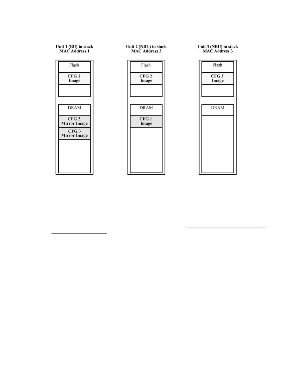
After a power cycle, all the CFG images in a stack are mirrored.
in stack on page 21 illustrates the CFG mirror images in a three-unit stack after the stack is
powered on. Unit 1 is the Base Unit (BU) and all other units are Non-Based Units (NBU).
• Unit 1 (BU) contains mirror images for unit 2 (CFG 2) and unit 3 (CFG3).
• Unit 2 (NBU), is the TEMP-BU. It contains a mirror image of unit 1 (CFG1), in case the
BU (unit 1) is removed from the stack.
• All three mirror images (CFG 1, CFG 2, and CFG 3) are active.
• Unit 2 is the AU of the CFG 2 mirror image.
• The Mac Address 2 is the AMA of the CFG2 mirror image.
Figure 1: CFG mirror process
20 Configuration — System April 2011
Auto Unit Replacement
Figure 1: CFG mirror process in stack
Adding a unit
In a stack that has no any INACTIVE CFG mirror images, a new unit causes the CFG image
of
the
stack after adding unit 4 on
is created in the BU (unit 1).
new unit to be mirrored in the stack. For example, in
page 22, after you add unit 4 to the stack, the CFG 4 mirror image
Figure 2: CFG mirror images in the
Configuration — System April 2011 21
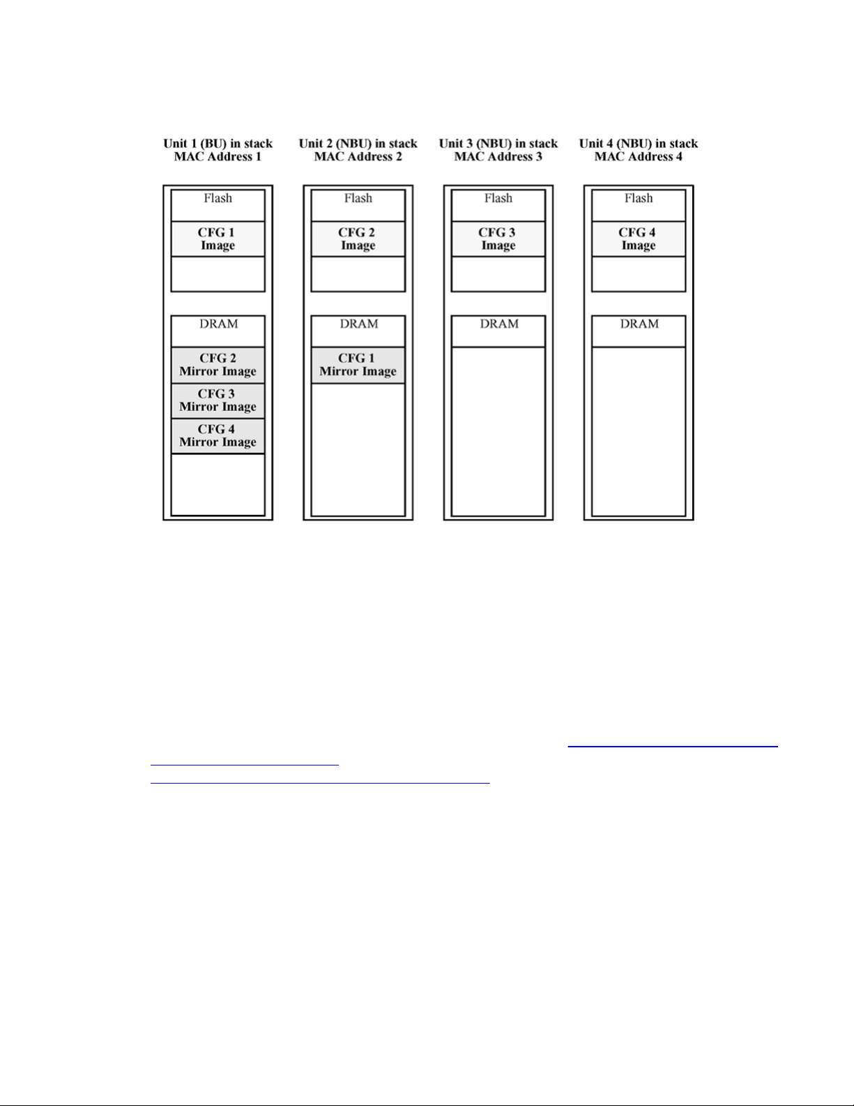
System configuration fundamentals
Figure 2: CFG mirror images in the stack after adding unit 4
Removing an NBU
When you remove an NBU from a stack, the related CFG mirror image in the stack becomes
INACTIVE.
The AUR feature ensures that the stack always has two copies of an INACTIVE CFG mirror
image.
For example, after you remove unit 4 from the stack shown in
the stack after adding unit 4 on page 22, the CFG 4 mirror image becomes INACTIVE (see
Figure 3: CFG mirror images after removing unit 4 on page 23).
INACTIVE CFG 4 mirror image is also created in unit 2.
These two copies must not reside in the same unit in the stack.
Figure 2: CFG mirror images in
Another copy of the
22 Configuration — System April 2011

Auto Unit Replacement
Figure 3: CFG mirror images after removing unit 4
Removing a BU
When you
images of the NBUs reside in the removed BU, the TEMP-BU mirrors all the CFG images of
the NBUs in the stack.
After you remove the BU from the stack shown in
after adding unit 4 on page 22, the
stack (see
page 24).
CFG mirror image.
remove a BU, the TEMP-BU assumes the role of the BU. Because all the CFG mirror
Figure 2: CFG mirror images in the stack
TEMP-BU (unit 2) must mirror all the CFG images in the
Figure 4: CFG mirror images in the stack after removing the BU (unit 1) on
The feature also ensures that the stack always has two copies of an INACTIVE
Configuration — System April 2011 23
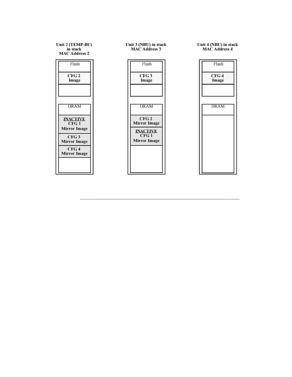
System configuration fundamentals
Figure 4: CFG mirror images in the stack after removing the BU (unit 1)
As
shown
• Unit 2 becomes the TEMP-BU.
• The CFG 1 mirror image (residing in unit 2) becomes INACTIVE.
• A second copy of the INACTIVE CFG 1 mirror image is created in unit 3.
• The TEMP-BU (unit 2) contains all CFG mirror images of the NBUs in the stack.
• The CFG 2 mirror image is created in unit 3. Unit 3 becomes the next TEMP-BU in case
in
Figure 4: CFG mirror images in the stack after removing the BU (unit 1) on
you remove the current TEMP-BU.
Restoring a CFG image
Restoring a CFG image overwrites the CFG image of a new unit in a stack with an INACTIVE
mirror image stored in the stack.
page 24
24 Configuration — System April 2011

Auto Unit Replacement
Important:
Restore a CFG image to a new unit happens only if you meet the following conditions.
• The AUR feature is enabled.
• At least one INACTIVE CFG mirror image exists in the stack.
• The MAC Address of the new unit is different from all the AMA of the INACTIVE CFG
mirror images in the stack.
The image restore process consists of the following steps.
Add a new unit to a stack:
a. If more than one INACTIVE CFG mirror image is in the stack, select the one
with the smallest unit ID for restoration.
b. Send the INACTIVE CFG mirror image in the stack to the new unit. The
INACTIVE CFG mirror image becomes ACTIVE.
c. The new unit saves the received CFG image to the flash drive.
d. The new unit resets itself.
For example, if you add a unit 5 (MAC Address 5) to the stack shown in Figure 4: CFG mirror
images in the stack after removing the BU (unit 1) on
page 24, the following occurs (see
Figure
5: CFG mirror images in the stack after adding unit 5 on page 26):
• The INACTIVE CFG 1 mirror image is copied to the CFG 5 image. Unit5 now has the
configuration of unit 1, which is no longer in the stack.
•
The INACTIVE CFG 1 mirror image in unit 2 becomes ACTIVE.
• The INACTIVE CFG 1 mirror image in unit 3 is removed.
• The MAC Address 5 of the unit 5 becomes the new AMA of the CFG1 mirror image.
Configuration — System April 2011 25
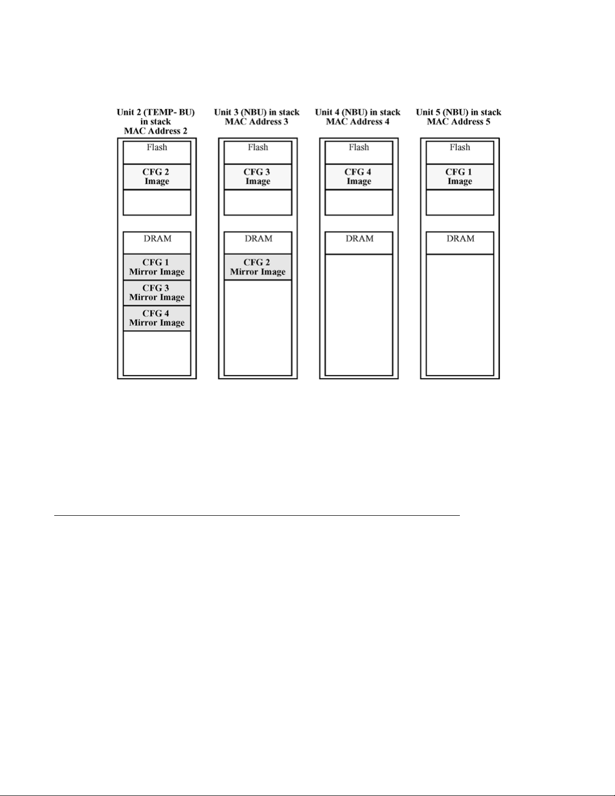
System configuration fundamentals
Figure 5: CFG mirror images in the stack after adding unit 5
Synchronizing the CFG mirror images with CFG images
A CFG mirror image is updated whenever a CFG flash drive synchronization occurs in the
AU.
Agent Auto Unit Replacement
Use the enhancement to the
Replacement (AAUR), to ensure that all units in a stack have the same software image by
inspecting units joining a stack and downloading the stack software image to any unit that has
a dissimilar image. AAUR is enabled by default.
Agent Auto Unit Replacement functions in the following manner:
Auto Unit Replacement functionality
, known as Agent Auto Unit
26 Configuration — System April 2011

1. When a stand-alone switch joins an AAUR-enabled stack, the switch software
image is inspected.
2. If the switch software image differs from the stack software image, the AAUR
functionality downloads the stack software image to the joining unit.
3. The joining unit is then reset and becomes a member of the stack upon a reboot.
The log file displays the following messages when AAUR completes successfully:
I 2 00:01:56:40 13 AAUR - Info: Receive request for agent image, start
transfer
I 2 00:01:56:48 14 AAUR - Info: Agent transfer finished
Diagnostics AUR (DAUR)
Auto Unit Replacement
Diagnostic Auto
of the non-base unit with the diagnostic image saved in the base unit of a stack. You must
enable AAUR on the stack first.
Release 5.2 and up support DAUR. Previous software releases do not support DAUR.
Diagnostic AUR updates the diagnostic image on inserted units in the same way that AAUR
performs this function for agent code.
The DAUR process starts when you enable AAUR if there is a stand-alone unit with a different
diagnostic image connected to the stack. This process updates all the units in the stack.
When you enable or disable AAUR, you also enable or disable DAUR. The default for AAUR
is enabled, so DAUR is also enabled by default.
There are no commands to separately enable or disable DAUR.
The log file displays the following messages when DAUR completes successfully:
I 2 00:02:01:20 18 DAUR - Info: Receive request for diag image, start
transfer
I 2 00:02:01:22 19 DAUR - Info: Diag transfer finished
Add a unit to a stack
Unit Replacement (DAUR) enables the switch to update the diagnostic image
When you enable AAUR on stack and then add another unit with different software image, this
unit does not join the stack immediately. The unit is now in stand-alone mode.
The new unit sends an AAUR request to the up stream port. If the unit does not receive an
answer, it sends a request to the down stream port. After the image transfers successfully, the
switch reboots.
If you add a unit with the base unit select switch set to off to a unit with base unit select switch
set, the non-base unit gets the diagnostic image from the base unit.
Configuration — System April 2011 27

System configuration fundamentals
When the switch finishes the diagnostic image version update, the switch performs an AAUR
check. If the new unit has the same agent image as the stack, the unit reboots. If the new unit
has a different agent image, the switch performs an AAUR.
Note:
The new unit added on a stack must have an agent image with software release 5.1.0 or
higher or AAUR and DAUR cannot upgrade the new unit.
The following table shows expected AAUR and DAUR behavior for different situations.
Table 4: Examples of AAUR and DAUR behavior in different situations
Stack master image and
diagnostic version
Software 5.0/5.1
Diagnostic 5.0/5.1
Software 5.0/5.1
Diagnostic 5.2
Software 5.2_SSH/non
SSH Diagnostic 5.2
Slave image
diagnostic version
Software 5.0/5.1
Diagnostic 5.0/5.1
Software 5.0/5.1
Diagnostic 5.2
Software 5.2
Diagnostic 5.0/5.1
Software 5.2
Diagnostic 5.2
Software 5.0/5.1
Diagnostic 5.0/5.1
Software 5.0/5.1
Diagnostic 5.2
Software 5.2_non
SSH/SSH Diagnostic
5.1
Expected behavior
Same image. Unit joins stack.
Same image. Unit joins stack.
AAUR performed. AAUR downgrades
the unit image and reboots the unit.
The unit joins the stack after the
reboot. No
is unavailable on 5.0/5.1
AAUR performed. AAUR upgrades the
unit image then reboots the stack.
DAUR upgrades the diagnostic image
then reboots the unit. The unit joins the
stack after the reboot.
AAUR performed. AAUR upgrades the
unit image then reboots the unit. Since
the diagnostic images are the same,
the unit joins the stack.
Since the diagnostic and agent images
are the different, DAUR upgrades the
diagnostic image, and then AAUR
transfers the agent. AAUR and DAUR
reboot the unit. The unit joins the stack
after the reboot.
DAUR performed as DAUR
Software 5.2_non
SSH/SSH Diagnostic
5.2
AAUR performs the agent image
transfer and reboots the unit. The unit
joins the stack after the reboot.
With version 5.2, when stack forced-mode is enabled and the base unit remains, Agent Auto
Unit Replacement and Diagnostic Unit Replacement are working as explained on the
preceding table.
28 Configuration — System April 2011

Large image file
If the
agent image size exceeds 6 Mb, the switch cannot perform the DAUR. The switch sends
an error message to the base unit. You must perform a manual image upgrade or downgrade
in this situation for both the diagnostic and agent images.
Stack Forced Mode
Stack Forced Mode
Forced
Stack
units breaks. The Stack Forced Mode allows you to manage one of the stand-alone devices
from a broken stack of two with the previous stack IP address.
If you enable Stack Forced Mode on a stack, you enable Stack Forced Mode on all units in the
stack. Stack Forced Mode becomes active only if the stack fails.
You can configure Stack Forced Mode through ACLI.
See
Setting Stack Forced Mode on page 109 for procedures to set the Stack Forced Mode
on a switch.
Stack Forced Mode applies to a stand-alone switch that is part of a stack of two units. When
functioning in this mode, the stand-alone switch keeps the previous stack IP settings (IP
address, netmask, gateway). That allows an administrator to reach the device through an IP
connection by telnet or EDM.
If one unit fails, the remaining unit ( base or non-base unit) keeps the previous stack IP settings.
The remaining unit issues a gratuitous ARP packet when it enters Stack Forced Mode, in order
for other devices on the network to update their ARP cache.
If the stack connection between the two units fails (a stack cable failure, for example), both
stand-alone units retain the IP settings. To detect if the other stack partner is also using the
previous stack IP settings, each device issues an ARP request on the IP address.
Mode allows one or both units to become stand-alone switches if a stack of two
When a failure occurs in a stack of 2 units when forced stack mode is enabled, the previous
non-base unit sends out a gratuitous ARP onto the management network. The purpose of
sending out this gratuitous ARP is so that the non-base unit of a failed 2 unit stack can
determine if the base unit is still operational and using the stack IP address. Such a failure
situation in which both the base unit and non-base unit were operational, but not part of a stack
could be possible if the 2 units in a stack were connected by a single stack cable and that stack
cable were then removed or failed. If the previous non-base unit receives a reply from the
previous base unit of the stack, the previous non-base unit knows that the previous base unit
is still operational and does not take over ownership of the stack IP address, but instead will
use the local switch IP address if configured. If on the other hand the previous non-base unit
does not receive a response from the previous base-unit; the previous non-base unit will now
take over ownership of the stack IP address and issue a gratuitous ARP with it's own MAC
Configuration — System April 2011 29

System configuration fundamentals
address to ensure that all devices on the management VLAN have their ARP caches
appropriately updated.
Stack Forced Mode allows non-EAP clients connected to the device to still authenticate
themselves and maintain connectivity to the network. Non-EAP clients authenticate by the
device with RADIUS, which is based on the stack IP address. In Stack Forced Mode, the device
retains the IP settings of the stack of two.
The functional unit stays in Stack Forced Mode until either a reboot or it joins a stack.
A settlement timer prevents several stack failures that occur at an interval of a few seconds to
lead to a device entering Stack Forced Mode after it was part of a stack larger than two units.
A device enters Stack Forced Mode if and only if it was part of a stack of two for 30 seconds
or longer.
If the switch is in Stack Force mode and you want to set a switch IPv6 address, you must first
delete the active IPv6 interface and then configure the switch IPv6 address. If you use Telnet,
SSH or EDM to change the settings, the switch will lose IPv6 connectivity to the switch. Avaya
recommends that you change the settings with the Console Interface to switch or use an IPv4
address for management.
IPv6 management
This module provides information about the IPv6 management feature of the A
Routing Switch 4500 Series switch platform.
IPv6 Management allows the user to configure an IPv6 address on the management VLAN.
This enables IPv6 connectivity. The management VLAN can have both an IPv4 and an IPv6
address configured simultaneously (Avaya Ethernet Routing Switch 4500 functions as a dual
stack network node).
There is no IPv6 routing support in the current phase and therefore only one IPv6 interface is
associated to the management VLAN. You can only perform IPv6 interface configuration
(enabling, assigning IPv6 address and prefix, changing other parameters, querying interface
statistics) from ACLI or through SNMP (EDM).
IPv6 Management adds support for new standard MIBs (IP-MIB—RFC 4293, TCP-MIB—RFC
4022, UDP-MIB—RFC 4113) as well as the enterprise MIB rcIpv6.
If the switch is in Stack Force mode and you want to set a switch IPv6 address, you must first
delete the active IPv6 interface and then configure the switch IPv6 address. If you use Telnet,
SSH, or EDM to change the settings, the switch will lose IPv6 connectivity to the switch. Avaya
recommends that you change the settings with the Console Interface to switch or use an IPv4
address for management.
vaya Ethernet
30 Configuration — System April 2011
Loading...