


 Loading...
a |
Low Cost Quad |
|
Voltage Controlled Amplifier |
||
|
|
|
|
|
SSM2164 |
|
|
|
FEATURES
Four High Performance VCAs in a Single Package 0.02% THD
No External Trimming 120 dB Gain Range
0.07 dB Gain Matching (Unity Gain) Class A or AB Operation
APPLICATIONS
Remote, Automatic, or Computer Volume Controls Automotive Volume/Balance/Faders
Audio Mixers Compressor/Limiters/Compandors Noise Reduction Systems Automatic Gain Controls
Voltage Controlled Filters
Spatial Sound Processors Effects Processors
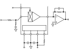
GENERAL DESCRIPTION
The SSM2164 contains four independent voltage controlled amplifiers (VCAs) in a single package. High performance
(100 dB dynamic range, 0.02% THD) is provided at a very low cost-per-VCA, resulting in excellent value for cost sensitive gain control applications. Each VCA offers current input and output for maximum design flexibility, and a ground referenced
–33 mV/dB control port.
All channels are closely matched to within 0.07 dB at unity gain, and 0.24 dB at 40 dB of attenuation. A 120 dB gain range is possible.
A single resistor tailors operation between full Class A and AB modes. The pinout allows upgrading of SSM2024 designs with minimal additional circuitry.
The SSM2164 will operate over a wide supply voltage range of
±4 V to ±18 V. Available in 16-pin P-DIP and SOIC packages, the device is guaranteed for operation over the extended industrial temperature range of –40°C to +85°C.
FUNCTIONAL BLOCK DIAGRAM
VC |
|
|
|
IIN |
|
VCA1 |
IIOUT |
VC |
|
|
|
IIN |
|
VCA2 |
IIOUT |
VC |
|
|
|
IIN |
|
VCA3 |
IIOUT |
VC |
|
|
|
IIN |
|
VCA4 |
IIOUT |
|
POWER SUPPLY |
|
|
AND BIASING CIRCUITRY |
|||
V+ |
GND |
V– |
MODE |
REV. 0
Information furnished by Analog Devices is believed to be accurate and reliable. However, no responsibility is assumed by Analog Devices for its use, nor for any infringements of patents or other rights of third parties which may result from its use. No license is granted by implication or otherwise under any patent or patent rights of Analog Devices.
One Technology Way, P.O. Box 9106, Norwood. MA 02062-9106, U.S.A. Tel: 617/329-4700 Fax: 617/326-8703
SSM2164–SPECIFICATIONS
ELECTRICAL SPECIFICATIONS(VS = ±15 V, AV = 0 dB, 0 dBu = 0.775 V rms, VIN = 0 dBu, RIN = ROUT = 30 kΩ, f = 1 kHz, –40°C < TA < +85°C using Typical Application Circuit (Class AB), unless otherwise noted. Typical specifications apply at TA = +25°C.)
|
|
|
SSM2164 |
|
|
Parameter |
Conditions |
Min |
Typ |
Max |
Units |
|
|
|
|
|
|
AUDIO SIGNAL PATH |
|
|
|
|
|
Noise |
VIN = GND, 20 kHz Bandwidth |
|
–94 |
|
dBu |
Headroom |
Clip Point = 1% THD+N |
|
22 |
|
dBu |
Total Harmonic Distortion |
2nd and 3rd Harmonics Only |
|
|
|
|
|
AV = 0 dB, Class A |
|
0.02 |
.1 |
% |
|
AV = ±20 dB, Class A1 |
|
0.15 |
|
% |
|
AV = 0 dB, Class AB |
|
0.16 |
|
% |
|
AV = ±20 dB, Class AB1 |
|
0.3 |
|
% |
Channel Separation |
|
|
–110 |
|
dB |
Unity Gain Bandwidth |
CF = 10 pF |
|
500 |
|
kHz |
Slew Rate |
CF = 10 pF |
|
0.7 |
|
mA/μs |
Input Bias Current |
|
|
±10 |
|
nA |
Output Offset Current |
VIN = 0 |
|
±50 |
|
nA |
Output Compliance |
|
|
±0.1 |
|
V |
CONTROL PORT |
|
|
|
|
kΩ |
Input Impedance |
|
|
5 |
|
|
Gain Constant |
(Note 2) |
|
–33 |
|
mV/dB |
Gain Constant Temperature Coefficient |
0 dB to –40 dB Gain Range3 |
|
–3300 |
|
ppm/°C |
Control Feedthrough |
|
1.5 |
8.5 |
mV |
|
Gain Matching, Channel-to-Channel |
AV = 0 dB |
|
0.07 |
|
dB |
|
AV = –40 dB |
|
0.24 |
|
dB |
Maximum Attenuation |
|
|
–100 |
|
dB |
Maximum Gain |
|
|
+20 |
|
dB |
|
|
|
|
|
|
POWER SUPPLIES |
|
±4 |
|
±18 |
|
Supply Voltage Range |
|
|
V |
||
Supply Current |
Class AB |
|
6 |
8 |
mA |
Power Supply Rejection Ratio |
60 Hz |
|
90 |
|
dB |
|
|
|
|
|
|
NOTES
1–10 dBu input @ 20 dB gain; +10 dBu input @ –20 dB gain. 2After 60 seconds operation.
3+25°C to +85°C.
Specifications subject to change without notice.
TYPICAL APPLICATION AND TEST CIRCUIT
VC |
14 |
|
|
|
|
|
100pF |
|
VC4 |
|
|
|
|
|
|
|
|
IIN |
15 |
|
VCA4 |
|
13 |
IIOUT |
30kΩ |
|
|
|
|
|
|
1/2 |
|
||
30kΩ |
|
|
|
|
|
|
VOUT4 |
|
V |
|
|
|
|
|
|
OP275 |
|
IN4 |
|
|
|
|
|
|
|
|
500Ω |
|
|
|
|
|
|
|
|
560pF |
|
POWER SUPPLY |
|
|
|
|
||
|
AND BIASING CIRCUITRY |
|
|
|
||||
|
9 |
8 |
16 |
|
1 |
|
|
|
|
|
V– |
GND |
V+ |
MODE |
|
|
|
|
|
0.1µF |
0.1µF |
|
RB (7.5kΩ CLASS A) |
|
||
|
|
|
|
|
|
|||
|
|
|
|
|
|
(OPEN CLASS AB) |
|
|
|
–15V |
+15V |
|
|
|
|
||
Figure 1. RIN = ROUT = 30 kΩ, CF = 100 pF. Optional RB = 7.5 kΩ, Biases Gain Core to Class A Operation. For Class AB, Omit RB.
–2– |
REV. 0 |

SSM2164
ABSOLUTE MAXIMUM RATINGS
Supply Voltage . . . . . . . . . . . . . . . . . . . . . . . . . . . . . . . . ±18 V Input, Output, Control Voltages . . . . . . . . . . . . . . . . V– to V+ Output Short Circuit Duration to GND . . . . . . . . . Indefinite Storage Temperature Range . . . . . . . . . . . . –65°C to +150°C Operating Temperature Range . . . . . . . . . . . . . –40°C to +85°C Junction Temperature Range . . . . . . . . . . . . –65°C to +150°C Lead Temperature Range (Soldering 60 sec) . . . . . . . . +300°C
Package Type |
θJA* |
θJC |
Units |
16-Pin Plastic DIP (P Suffix) |
76 |
33 |
°C/W |
16-Pin SOIC (S Suffix) |
92 |
27 |
°C/W |
*θJA is specified for the worst case conditions; i.e., θJA is specified for device in socket for P-DIP packages, θJA is specified for device soldered in circuit board for SOIC package.
ORDERING GUIDE
|
Temperature |
Package |
Package |
Model |
Range |
Description |
Options |
|
|
|
|
SSM2164P |
–40°C to +85°C |
Plastic DIP |
N-16 |
SSM2164S |
–40°C to +85°C |
Narrow SOIC |
R-16A |
PIN CONFIGURATION
16-Lead Epoxy DIP and SOIC
|
|
|
|
|
|
|
MODE |
1 |
|
|
|
16 |
V+ |
|
|
|
|
|
|
|
IIN1 |
2 |
|
|
|
15 |
IIN4 |
|
|
|
|
|
|
|
VC1 |
3 |
|
|
|
14 |
VC4 |
IOUT1 |
|
SSM2164 |
|
IOUT4 |
||
4 |
13 |
|||||
|
|
TOP VIEW |
|
|
||
IOUT2 |
5 |
(Not to Scale) |
12 |
IOUT3 |
||
|
|
|||||
VC2 |
6 |
|
|
|
11 |
VC3 |
IIN2 |
|
|
|
|
|
IIN3 |
7 |
|
|
|
10 |
||
|
|
|
|
|
|
|
GND |
8 |
|
|
|
9 |
V– |
|
|
|
|
|
|
|
CAUTION
ESD (electrostatic discharge) sensitive device. Electrostatic charges as high as 4000 V readily accumulate on the human body and test equipment and can discharge without detection. Although the SSM2164 features proprietary ESD protection circuitry, permanent damage may occur on devices subjected to high energy electrostatic discharges. Therefore, proper ESD precautions are recommended to avoid performance degradation or loss of functionality.
WARNING!
ESD SENSITIVE DEVICE
REV. 0 |
–3– |

SSM2164
Typical Performance Characteristics
|
1.0 |
|
|
|
|
|
|
CLASS A |
|
|
|
|
|
VS = ±15V |
|
|
|
|
|
LPF = 80kHz |
|
|
|
+ N – % |
|
|
AV = + 20dB |
|
|
0.1 |
|
|
|
|
|
THD |
|
|
AV |
= – 20dB |
|
|
|
|
|
||
|
|
|
AV = 0dB |
|
|
|
0.01 |
|
|
|
|
|
20 |
100 |
1k |
10k |
20k |
|
|
|
FREQUENCY – Hz |
|
|
Figure 2. THD+N vs. Frequency, Class A
|
1.0 |
|
|
|
|
|
|
|
|
CLASS AB |
|
|
|
|
|
VS = ±15V |
|
|
|
|
|
LPF = 80kHz |
|
|
|
AV = +20dB |
AV = –20dB |
|
|
|
|
|
|
|
|
N – % |
0.1 |
|
AV = 0dB |
|
|
THD + |
|
|
|
|
|
|
0.01 |
|
|
|
|
|
20 |
100 |
1k |
10k |
20k |
FREQUENCY – Hz
Figure 3. THD+N vs. Frequency Class, AB
300 |
|
|
|
|
|
|
|
|
|
|
|
|
|
|
|
|
|
|
|
|
|
|
|
|
|
|
|
|
|
|
280 |
|
|
|
|
|
|
|
|
|
|
|
|
|
|
|
|
|
VS = ±15V |
|
|
|
|
|
|||||||
|
|
|
|
|
|
|
|
|
|
|
|
|
|
|
|
|
|
|
|
|
||||||||||
260 |
|
|
|
|
|
|
|
|
|
|
|
|
|
|
|
|
|
|
|
|
|
|
||||||||
|
|
|
|
|
|
|
|
|
|
|
|
|
|
|
|
|
TA = +25°C |
|
|
|
|
|
||||||||
240 |
|
|
|
|
|
|
|
|
|
|
|
|
|
|
|
|
|
1200 CHANNELS |
|
|
||||||||||
|
|
|
|
|
|
|
|
|
|
|
|
|
|
|
|
|
|
|||||||||||||
220 |
|
|
|
|
|
|
|
|
|
|
|
|
|
|
|
|
|
|
|
|
|
|
|
|
|
|
|
|
|
|
|
|
|
|
|
|
|
|
|
|
|
|
|
|
|
|
|
|
|
|
|
|
|
|
|
|
|
|
|
||
200 |
|
|
|
|
|
|
|
|
|
|
|
|
|
|
|
|
|
|
|
|
|
|
|
|
|
|
|
|
|
|
|
|
|
|
|
|
|
|
|
|
|
|
|
|
|
|
|
|
|
|
|
|
|
|
|
|
|
|
|
||
180 |
|
|
|
|
|
|
|
|
|
|
|
|
|
|
|
|
|
|
|
|
|
|
|
|
|
|
|
|
|
|
|
|
|
|
|
|
|
|
|
|
|
|
|
|
|
|
|
|
|
|
|
|
|
|
|
|
|
|
|
||
160 |
|
|
|
|
|
|
|
|
|
|
|
|
|
|
|
|
|
|
|
|
|
|
|
|
|
|
|
|
|
|
|
|
|
|
|
|
|
|
|
|
|
|
|
|
|
|
|
|
|
|
|
|
|
|
|
|
|
|
|
||
UNITS |
|
|
|
|
|
|
|
|
|
|
|
|
|
|
|
|
|
|
|
|
|
|
|
|
|
|
|
|
|
|
140 |
|
|
|
|
|
|
|
|
|
|
|
|
|
|
|
|
|
|
|
|
|
|
|
|
|
|
|
|
|
|
120 |
|
|
|
|
|
|
|
|
|
|
|
|
|
|
|
|
|
|
|
|
|
|
|
|
|
|
|
|
|
|
100 |
|
|
|
|
|
|
|
|
|
|
|
|
|
|
|
|
|
|
|
|
|
|
|
|
|
|
|
|
|
|
|
|
|
|
|
|
|
|
|
|
|
|
|
|
|
|
|
|
|
|
|
|
|
|
|
|
|
|
|
||
80 |
|
|
|
|
|
|
|
|
|
|
|
|
|
|
|
|
|
|
|
|
|
|
|
|
|
|
|
|
|
|
60 |
|
|
|
|
|
|
|
|
|
|
|
|
|
|
|
|
|
|
|
|
|
|
|
|
|
|
|
|
|
|
|
|
|
|
|
|
|
|
|
|
|
|
|
|
|
|
|
|
|
|
|
|
|
|
|
|
|
|
|
||
40 |
|
|
|
|
|
|
|
|
|
|
|
|
|
|
|
|
|
|
|
|
|
|
|
|
|
|
|
|
|
|
|
|
|
|
|
|
|
|
|
|
|
|
|
|
|
|
|
|
|
|
|
|
|
|
|
|
|
|
|
||
20 |
|
|
|
|
|
|
|
|
|
|
|
|
|
|
|
|
|
|
|
|
|
|
|
|
|
|
|
|
|
|
0 |
|
|
|
|
|
|
|
|
|
|
|
|
|
|
|
|
|
|
|
|
|
|
|
|
|
|
|
|
|
|
|
|
|
|
|
|
|
|
|
|
|
|
|
|
|
|
|
|
|
|
|
|
|
|
|
|
|
|
|
||
0.005 |
0.010 |
0.015 |
0.020 |
0.025 |
0.030 |
0.035 |
0.040 |
0.045 |
0.050 |
|||||||||||||||||||||
|
|
|
|
|
|
|
|
|
|
|
|
THD – % |
|
|
|
|
|
|
|
|
|
|
|
|
|
|||||
Figure 4. THD Distribution, Class A
210 |
|
|
|
|
|
|
|
|
|
|
|
|
|
|
|
|
|
|
|
|
|
|
|
|
|
|
|
|
|
|
|
|
|
|
|
|
|
|
|
|
|
|
|
|
|
|
|
|
|
|
|
|
|
|
|
|
|
|
|
|
|
||
200 |
|
|
|
|
|
|
|
|
|
|
|
|
|
|
|
|
|
|
|
VS = ±15V |
|
|
|
|
|
|
|||||
190 |
|
|
|
|
|
|
|
|
|
|
|
|
|
|
|
|
|
|
|
|
|
|
|
|
|
||||||
|
|
|
|
|
|
|
|
|
|
|
|
|
|
|
|
|
|
|
|
|
|
|
|
||||||||
180 |
|
|
|
|
|
|
|
|
|
|
|
|
|
|
|
|
|
|
|
TA = +25°C |
|
|
|
|
|
|
|||||
170 |
|
|
|
|
|
|
|
|
|
|
|
|
|
|
|
|
|
|
|
1200 CHANNELS |
|
|
|||||||||
160 |
|
|
|
|
|
|
|
|
|
|
|
|
|
|
|
|
|
|
|
|
|
|
|
|
|
|
|
|
|
|
|
150 |
|
|
|
|
|
|
|
|
|
|
|
|
|
|
|
|
|
|
|
|
|
|
|
|
|
|
|
|
|
|
|
|
|
|
|
|
|
|
|
|
|
|
|
|
|
|
|
|
|
|
|
|
|
|
|
|
|
|
|
|
|
||
140 |
|
|
|
|
|
|
|
|
|
|
|
|
|
|
|
|
|
|
|
|
|
|
|
|
|
|
|
|
|
|
|
|
|
|
|
|
|
|
|
|
|
|
|
|
|
|
|
|
|
|
|
|
|
|
|
|
|
|
|
|
|
||
130 |
|
|
|
|
|
|
|
|
|
|
|
|
|
|
|
|
|
|
|
|
|
|
|
|
|
|
|
|
|
|
|
|
|
|
|
|
|
|
|
|
|
|
|
|
|
|
|
|
|
|
|
|
|
|
|
|
|
|
|
|
|
||
120 |
|
|
|
|
|
|
|
|
|
|
|
|
|
|
|
|
|
|
|
|
|
|
|
|
|
|
|
|
|
|
|
UNITS |
|
|
|
|
|
|
|
|
|
|
|
|
|
|
|
|
|
|
|
|
|
|
|
|
|
|
|
|
|
|
|
110 |
|
|
|
|
|
|
|
|
|
|
|
|
|
|
|
|
|
|
|
|
|
|
|
|
|
|
|
|
|
|
|
100 |
|
|
|
|
|
|
|
|
|
|
|
|
|
|
|
|
|
|
|
|
|
|
|
|
|
|
|
|
|
|
|
90 |
|
|
|
|
|
|
|
|
|
|
|
|
|
|
|
|
|
|
|
|
|
|
|
|
|
|
|
|
|
|
|
80 |
|
|
|
|
|
|
|
|
|
|
|
|
|
|
|
|
|
|
|
|
|
|
|
|
|
|
|
|
|
|
|
70 |
|
|
|
|
|
|
|
|
|
|
|
|
|
|
|
|
|
|
|
|
|
|
|
|
|
|
|
|
|
|
|
|
|
|
|
|
|
|
|
|
|
|
|
|
|
|
|
|
|
|
|
|
|
|
|
|
|
|
|
|
|
||
60 |
|
|
|
|
|
|
|
|
|
|
|
|
|
|
|
|
|
|
|
|
|
|
|
|
|
|
|
|
|
|
|
|
|
|
|
|
|
|
|
|
|
|
|
|
|
|
|
|
|
|
|
|
|
|
|
|
|
|
|
|
|
|
|
50 |
|
|
|
|
|
|
|
|
|
|
|
|
|
|
|
|
|
|
|
|
|
|
|
|
|
|
|
|
|
|
|
|
|
|
|
|
|
|
|
|
|
|
|
|
|
|
|
|
|
|
|
|
|
|
|
|
|
|
|
|
|
|
|
40 |
|
|
|
|
|
|
|
|
|
|
|
|
|
|
|
|
|
|
|
|
|
|
|
|
|
|
|
|
|
|
|
30 |
|
|
|
|
|
|
|
|
|
|
|
|
|
|
|
|
|
|
|
|
|
|
|
|
|
|
|
|
|
|
|
|
|
|
|
|
|
|
|
|
|
|
|
|
|
|
|
|
|
|
|
|
|
|
|
|
|
|
|
|
|
|
|
20 |
|
|
|
|
|
|
|
|
|
|
|
|
|
|
|
|
|
|
|
|
|
|
|
|
|
|
|
|
|
|
|
10 |
|
|
|
|
|
|
|
|
|
|
|
|
|
|
|
|
|
|
|
|
|
|
|
|
|
|
|
|
|
|
|
|
|
|
|
|
|
|
|
|
|
|
|
|
|
|
|
|
|
|
|
|
|
|
|
|
|
|
|
|
|
|
|
0 |
|
|
|
|
|
|
|
|
|
|
|
|
|
|
|
|
|
|
|
|
|
|
|
|
|
|
|
|
|
|
|
0.00 |
0.05 |
0.10 |
0.15 |
0.20 |
0.25 |
0.30 |
0.35 |
0.40 |
0.45 |
||||||||||||||||||||||
|
|
|
|
|
|
|
|
|
|
|
|
|
|
THD – % |
|
|
|
|
|
|
|
|
|
|
|
|
|||||
Figure 5. THD Distribution, Class AB
|
1.0 |
|
|
|
|
|
|
VS ±15V |
|
|
|
|
|
AV = 0dB |
|
|
|
|
|
LPF = 22kHz |
|
|
|
N – % |
0.1 |
CLASS AB |
|
|
|
+ |
|
|
|
|
|
THD |
|
|
|
|
|
|
|
CLASS A |
|
|
|
|
0.01 |
|
|
|
|
|
20 |
100 |
1k |
10k |
20k |
|
|
AMPLITUDE – VRMS |
|
|
|
Figure 6. THD+N vs. Amplitude
0.10
LPF = 80kHz
0.08
% |
0.06 |
THD + N – |
0.04 |
0.02
0
0 |
±4 |
±8 |
±12 |
±16 |
±20 |
SUPPLY – Volts
Figure 7. THD+N vs. Supply Voltage, Class A
–4– |
REV. 0 |
Loading...