

Evaluation Kit User Guide
UG-041
One Technology Way • P. O . Box 9106 • Norwood, MA 02062-9106, U.S.A. • Tel : 781.329.4700 • Fax : 781.461.3113 • www.analog.com
ADuC8xx Evaluation Kit Getting Started User Guide
INTRODUCTION
This user guide functions as a tutorial to introduce the various
tools that are part of the MicroConverter® QuickStart™ development system. Because these tools are ADuC8xx generic, this
user guide applies to all ADuC8xx parts.
The ADuC8xx parts and the evaluation boards referenced in
this tutorial guide are shown in Table 1. The tools described in
this user guide are listed in Table 2.
Table 2. Software Tools
Tool Executable Function
Metalink 8051 Cross
Assembler
Windows Serial Downloader
(WSD)
Integrated Development
Environment (IDE) Assembly
Source
Windows Analog Software
Program (WASP)
USB-EA Emulation None This emulation is used for nonintrusive debugging using Keil or IAR development tools. It is also
Asm51.exe This assembler takes an assembly language source file created with a text editor and saved with a
WSD.exe The WDS is a Windows® software program developed by Analog Devices, Inc., that allows one to
Available
online
WASP.exe WASP is an analysis tool allowing easy measurement of the analog noise performance of the
.asm extension, and translates it into two files: a listing file output (.lst) and a machine language
object file in standard Intel HEX format (.hex).
serially download standard Intel HEX files created by the ASM51 assembler to the MicroConverter
while in circuit.
Keil and IAR provide a complete IDE integrating all tools necessary to edit, assemble, simulate, and
debug assembly source code via the serial port. Download the latest 8051 tools from the official
Keil-An ARM Company or IAR Systems Software, Inc. company website(s).
MicroConverter.
used for serial downloading via the EA pin and the WSD software.
Table 1. ADuCxx Parts and Evaluation Boards
Part Evaluation Board
ADuC812 MicroConverter SAR Evaluation Board, Rev. A3
ADuC814 EVAL-ADUC814QS SAR Evaluation Board, Rev. B1
ADuC831 MicroConverter SAR Evaluation Board, Rev. A3
ADuC832 MicroConverter SAR Evaluation Board, Rev. A3
ADuC841 MicroConverter SAR Evaluation Board, Rev. A3
ADuC842/
ADuC843
ADuC816 MicroConverter Σ-Δ Evaluation Board, Rev. B
ADuC824
ADuC834
ADuC836
ADuC845
ADuC847
MicroConverter SAR Evaluation Board, Rev. A3
MicroConverter
MicroConverter
MicroConverter
MicroConverter
MicroConverter Σ-Δ
Σ-Δ Evaluation Board, Rev. B
Σ-Δ Evaluation Board, Rev. B
Σ-Δ Evaluation Board, Rev. B
Σ-Δ Evaluation Board, Rev. 0
Evaluation Board, Rev. 0
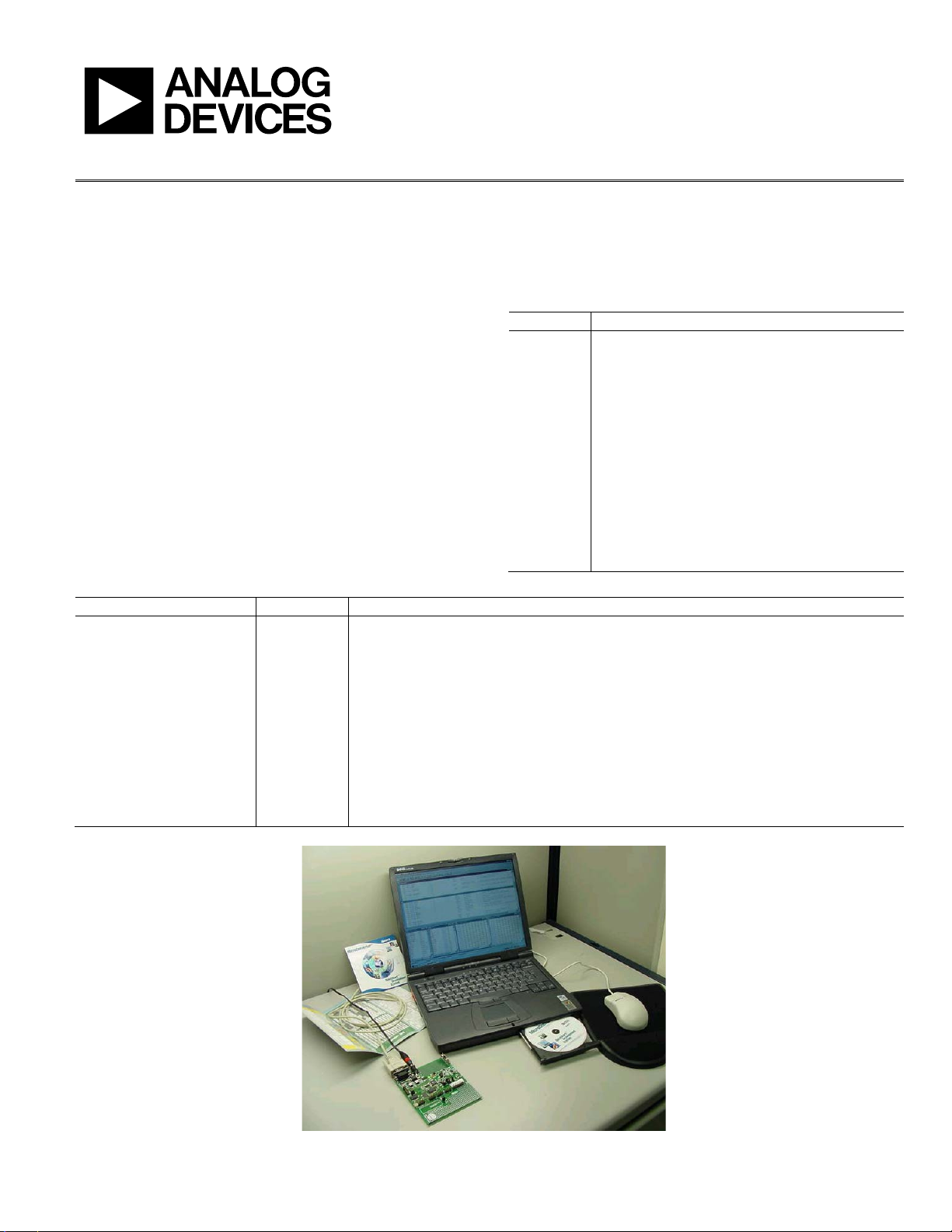
Figure 1. The ADuC8xx QuickStart Development System
Please see the last page for an important warning and disclaimers. Rev. A | Page 1 of 16
08412-001

UG-041 Evaluation Kit User Guide
TABLE OF CONTENTS
Introduction ...................................................................................... 1
Revision History ............................................................................... 2
Installation ......................................................................................... 3
Installing from the CD ................................................................. 3
The Metalink 8051 Cross Assembler ............................................. 4
Using the Metalink Assembler .................................................... 4
The ADuC Windows Serial Downloader ...................................... 5
Opening the Windows Serial Downloader ............................... 5
Downloading Using the WSD .................................................... 5
Running the Downloaded File .................................................... 5
Using the PC COM Port .............................................................. 6
Downloading via the USB-EA Emulator .................................. 6
USB-EA Emulator for Debugging .................................................. 7
REVISION HISTORY
10/09—Rev. 0 to Rev. A
Changes to Keil/IAR Limitations when Using the USB_EA
Emulator Section .............................................................................. 9
Added Timing Considerations when Debugging Section ........ 10
8/09—Revision 0: Initial Version
Connecting the USB-EA Emulator to the Target Board ..........7
Drivers for the USB-EA Emulator ..............................................7
Configuring Keil Tools for the USB-EA Emulator ...................8
Configuring IAR Tools for the USB-EA Emulator ...................9
Keil/IAR Limitations when Using the USB-EA Emulator .......9
Timing Considerations when Debugging ............................... 10
The ADuC WASP ........................................................................... 11
SAR WASP .................................................................................. 11
Σ-Δ WASP ................................................................................... 12
Installed Documentation and Code Directory........................... 13
C:\ADuC\Documentation\ADuC8XX\ ...................................... 13
Installed Code Locations ........................................................... 13
Rev. A | Page 2 of 16

Evaluation Kit User Guide UG-041
INSTALLATION
INSTALLING FROM THE CD
1. Insert the MicroConverter QuickStart Development
System CD-ROM into your CD ROM drive, select the
CD-ROM drive, and double-click on the setup.exe file.
2. Follow the screen instructions to install the software on
your PC.
Note the following regarding installation:
• Although you can install the software onto any hard drive
and into any directory, the remainder of this user guide
assumes that you have installed the software at the default
location of C:\ADuC.
• If you already have a previous ADuC8xx QuickStart
Development System tool suite installed on your machine,
this version may also be installed by default at C:\ADuC.
The ADuC8xx software tools installation automatically
updates any previous ADuC8xx tools in this directory.
Rev. A | Page 3 of 16
UG-041 Evaluation Kit User Guide
THE METALINK 8051 CROSS ASSEMBLER
The Metalink 8051 Cross Assembler takes an assembly language
source file created with a text editor and saved with a .asm
extension, and creates two files: an output list file (.lst) and a
machine language object file in standard Intel HEX format (.hex).
The list file output (.lst) displays the results of the assembler
operation, including any syntax or other errors present in the
original source code.
The Intel HEX file (.hex) is used to program the part using the
Windows serial downloader (WSD).
USING THE METALINK ASSEMBLER
1. In the C:\ADuC\ASM51 directory, double-click on the
ASM51.exe executable.
2. In the DOS window, enter the path of the assembly file
you want to assemble. For example, to assemble the
example file C:\ADuC\Download\DemoCode.asm, enter
C:\ADuC\ Download\DemoCode.asm.
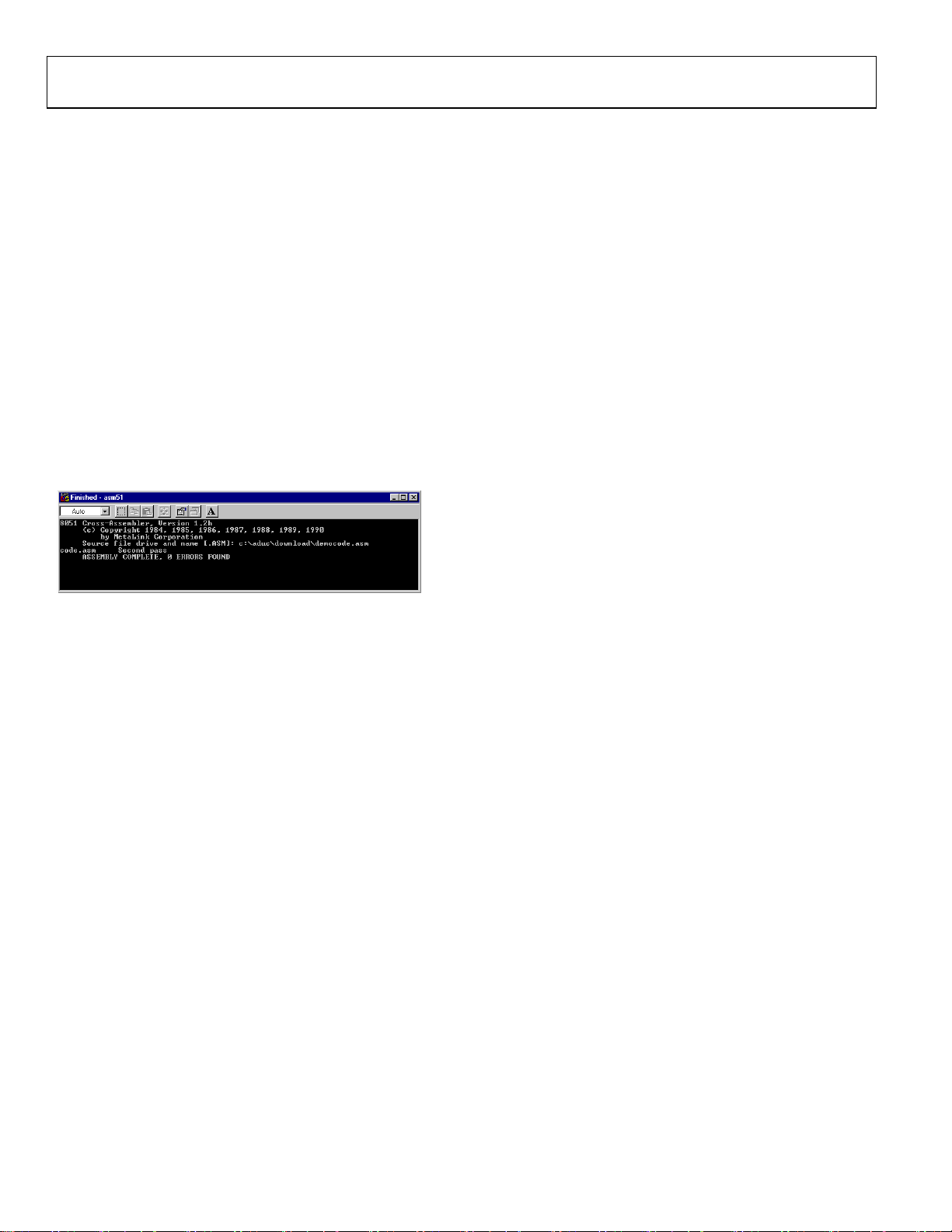
The assembler displays ASSEMBLY COMPLETE, 0 ERRORS
FOUND indicating assembly of the file and creation of the hex
and list files (that is, DemoCode.hex and DemoCode.lst) with
the assembly input file (that is, DemoCode.asm). If the assembler indicates assembly errors, view the list file (DemoCode.lst)
to examine the errors. To view the list file, open it with
Microsoft® Notepad or any standard text editor.
If the assembler returns an error message indicating a failure to
read the A drive or a fatal error opening a file on the A drive,
then it is most likely failing to find the MOD52 or MOD8xx file
referenced by the assembly file. Make sure all MOD files (plus
any other “include” files referenced in your assembly code) are
located in the C:\ADuC\ASM51 directory.
The ASM51.exe program can be copied/moved to another
directory to prevent typing in the long path name repeatedly.
Make sure that the relevant MOD files are also moved with
the ASM51.exe program.
For additional details on the use of the Metalink ASM51 assembler,
refer to the ASM51 user manual at C:\ADuC\ASM51\ASM51.pdf.
This manual was provided on the evaluation kit CD.
08412-002
Figure 2. DOS Window
Rev. A | Page 4 of 16
Evaluation Kit User Guide UG-041
THE ADuC WINDOWS SERIAL DOWNLOADER
The Windows serial downloader (WSD) is a Windows software
program that allows a user to serially download standard Intel
HEX files created by the ASM51 assembler to the MicroConverter via the serial port. The standard Intel HEX file is
downloaded into the on-chip Flash/EE program memory via
a selected PC serial port (COM1 to COM32). The WSD also
incorporates the protocols for downloading to Flash/EE data
memory, and setting security bits and various run options.
OPENING THE WINDOWS SERIAL DOWNLOADER
1. Power up the evaluation board using the 9 V power supply.
Connect the evaluation board header, J4, to your PC
COM1 serial port using the RS-232 dongle cable provided.
The PC serial COM port may be changed from COM1 via
the WSD configuration option.
2. Place the MicroConverter into serial download mode.
• To enter serial download mode on the ADuC814:
Connect S3 into the DLOAD/DEBUG position and
press Reset.
• To enter serial download mode on any of the other
ADuC8xx products:
Hold down the Serial Download button, and press
and release the Reset button.
3. From the Start menu, choose ProgramsÆADuCÆWSD.
This launches the Windows serial downloader application.
The WSD executable, provided on the CD, is located at
C:\ADuC\Download\WSD.exe.
The WSD automatically sends the reset command to the
MicroConverter. If the MicroConverter is in serial download
mode and the communications between the PC and the
evaluation board are setup correctly, then the WSD should
display ADuC8xx version 2.Y above the top right corner of
the status box.
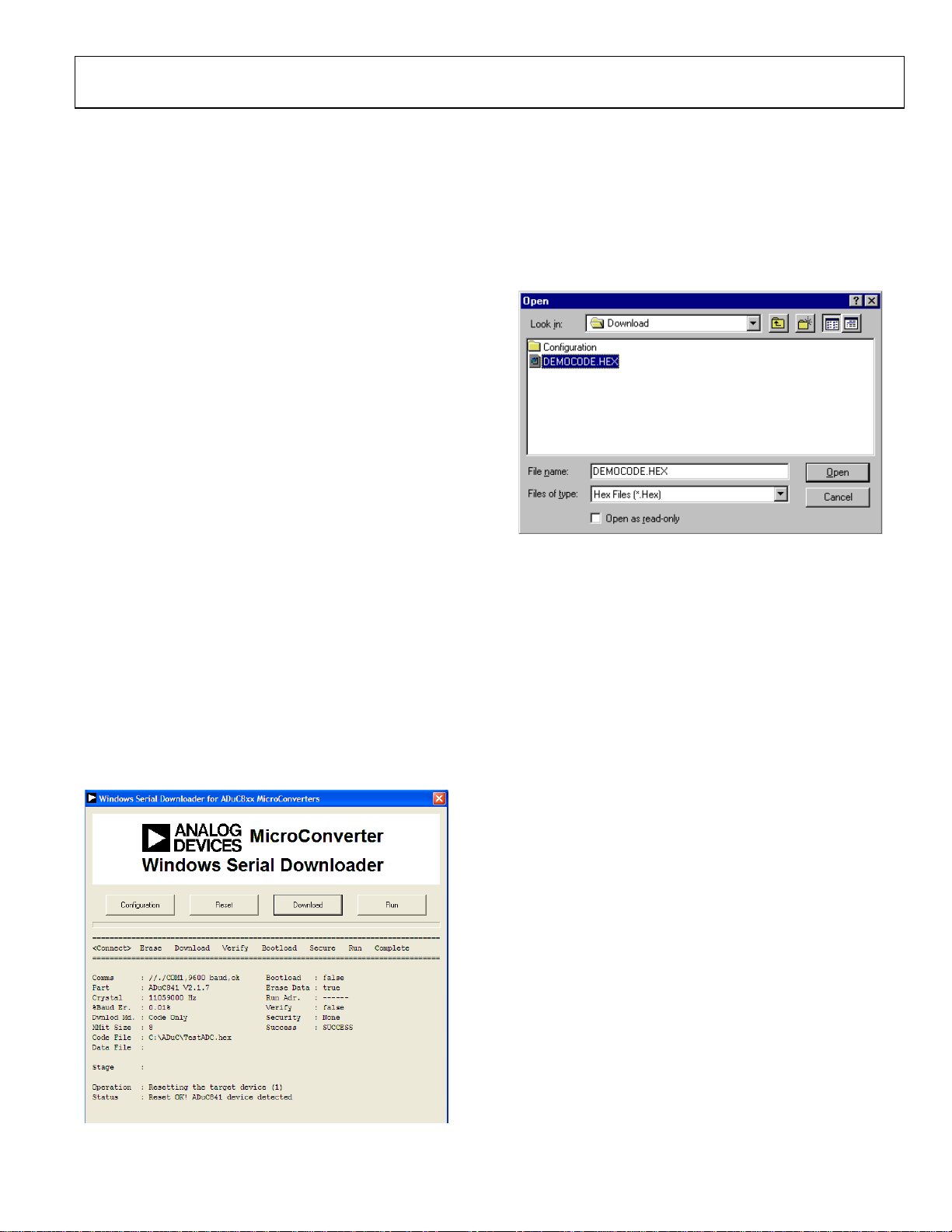
DOWNLOADING USING THE WSD
From the Windows serial download window
1. Click Download.
2. Select the file at C:\ADuC\Download\DemoCode.hex.
3. Double-click on the selected file or click Open to down-
load the file.
Figure 4. Open Window
While the file is downloading, a progress bar appears indicating
how much of the file has been downloaded.
Once the file has been successfully downloaded, the progress
bar disappears and the status box is updated with the message
DOWNLOADING CODE
[C:\ADuC\Download\DEMOCODE.HEX]:..
OK
RUNNING THE DOWNLOADED FILE
Running Using the WSD
From the Windows serial download window, click Run. The
status box is updated with the message
Run OK!
The program starts running from Address 0000h; this is
indicated by a flashing LED on the evaluation board.
To perform additional downloads, repeat Step 2 in the Opening
the Windows Serial Downloader section and click Reset on
the WSD.
Manual Run Option
Click Reset on the evaluation board with the Serial Download
switch released (for the ADuC814, switch S3 to the Normal
position). The program starts running automatically after reset
and the LED flashes.
Note that DemoCode.hex causes an LED to blink on the eval
board. The rate of blinking is reduced each time the Int0 button
is pressed.
08412-004
Figure 3. Windows Serial Downloader Window
8412-003
Rev. A | Page 5 of 16

UG-041 Evaluation Kit User Guide
Additional Download/Run Options
The MicroConverter incorporates a serial download protocol
that also allows various download/run options (see uC004 at
C:\ADuC\Documentation\TechNotes provided on the CD).
These options, as well as other options including Erase, can be
selected via the Configuration window as shown in Figure 5.
Remember, this window appears after clicking the Configuration
button found on the front panel of the WSD shown in Figure 3.
Certain options may be grayed out depending on the
MicroConverter used.
Figure 5. Configuration Window
On the Configuraton window
1. Check Run Automatically after Download and click OK.
2. Enter serial download mode as described in Step 2 in the
Opening the Windows Serial Downloader section.
3. Download as described in the Downloading Using the
WSD section.
08412-005
The program starts running automatically after download; this
is indicated by the flashing LED.
USING THE PC COM PORT
Only one application at a time may use the PC serial port.
The WSD only uses the PC COM serial port when
• Resetting the device
• Downloading to the device
• Sending the run command to the device
Therefore, the WSD does not have to be closed before launching
the debugger/WASP/hyperterminal or any other application
that uses the PC COM serial port.
However, if another application that uses the PC serial port
is open, then the WSD is not able to communicate with
the MicroConverter until the PC serial port is released by
disconnecting/closing the other application.
DOWNLOADING VIA THE USB-EA EMULATOR
The USB-EA Emulator Debugging section discusses using the
USB-EA emulator for debug purposes. However, it is also
possible to use the USB-EA emulator to serially program the
ADuC8xx parts via the EA pin. This does not require a
connection to the UART pins.
After installing the USB-EA emulator, your PC assigns the
emulator a COM port.
When using the USB-EA emulator to download to the
ADuC8xx, select this COM port in the WSD application and
follow the instructions provided in the USB_EA Emulator
Debugging section.
Rev. A | Page 6 of 16

Evaluation Kit User Guide UG-041
USB-EA EMULATOR FOR DEBUGGING
The USB-EA emulator allows nonintrusive debugging of the
ADuC8xx series of devices. The USB-EA pod is either shipped
as part of the Quick Start Plus kits or purchased separately.
The following parts are supported by the USB-EA emulator:
• ADuC831
• ADuC832
• ADuC841
• ADuC842/ADuC843
• ADuC834
• ADuC836
• ADuC845
• ADuC847
• ADuC848
Note that the ADuC812/ADuC814/ADuC816/ADuC824 are
not supported by the USB-EA emulator.
The debugger interfaces to the ADuC8xx via a single pin—the
EA pin of the ADuC8xx part. To enter debug mode, first place
the part into download mode by toggling the RESET pin while
holding the serial download pin low. When using the evaluation boards, this involves keeping the Serial Download button
pressed while toggling the Reset button.
When the drivers are installed and the USB-EA dongle is
connected to the PC, it appears as an extra COM port under
the Device Manager window as shown in Figure 7.
CONNECTING THE USB-EA EMULATOR TO THE TARGET BOARD
The pod connects to a PC via a standard mini-USB cable. It
connects to a target board via a 2-pin header.
Figure 6. Target Board Connected to the USB EA Emulator
DRIVERS FOR THE USB-EA EMULATOR
If the USB drivers for the USB-EA dongle do not install
automatically on your PC, then download drivers for the
FT245R part for your operating system from the official website
for the Future Technology Devices International Ltd.
08412-007
Figure 7. Device Manager Window
The older versions of the Keil tools only work with COM ports
numbered COM8 or lower. If your PC allocates a COM port
number of COM9 or higher, change the COM port number to
a lower number by completing the following steps:
1. Right-click your mouse on the USB Serial Port entry in
the Device Manager window and then select Properties.
08412-008
08412-006
Figure 8. Choosing the USB Entry in the Device Manger Window
2. Next, select the Port Settings tab and click Advanced.
Rev. A | Page 7 of 16

UG-041 Evaluation Kit User Guide
CONFIGURING KEIL TOOLS FOR THE USB-EA EMULATOR
1. Open your project using a recent version of Keil PK51
development software.
2. From the Keil uVision menu, select FlashÆConfigure
Flash ToolsÆDebug.
3. Make the selections as shown on the right side of
Figure 12, making sure to select the ADI Monitor Driver.
8412-009
Figure 9. USB Serial Port Properties Window
3. In the Advanced Settings window, change the COM Port
Number to a port lower than COM 9 by making an
appropriate selection.
Figure 10. Advanced Settings Window
4. Click OK and return to the main Device Manager window.
5. To update the newly selected COM port, unplug and
replug the USB cable to the USB-EA dongle and the newly
selected COM port should appear in the Device Manager
window.
Figure 11. COM Port Selection in Device Manager Window
08412-011
8412-012
Figure 12. Options for Target WIndow
4. Click Settings at the top right (see Figure 12) and then
select 1-Pin Pod and the COM port assigned to the
emulator as shown in Figure 13. Use the Device Manager
to identify the appropriate COM port.
08412-010
Figure 13. Target Setup Window
08412-013
The latest 8051 tools are available for download from the Keil
website.
Rev. A | Page 8 of 16
Evaluation Kit User Guide UG-041
CONFIGURING IAR TOOLS FOR THE USB-EA EMULATOR
1. Open your project using a recent version of IAR EW51
development software.
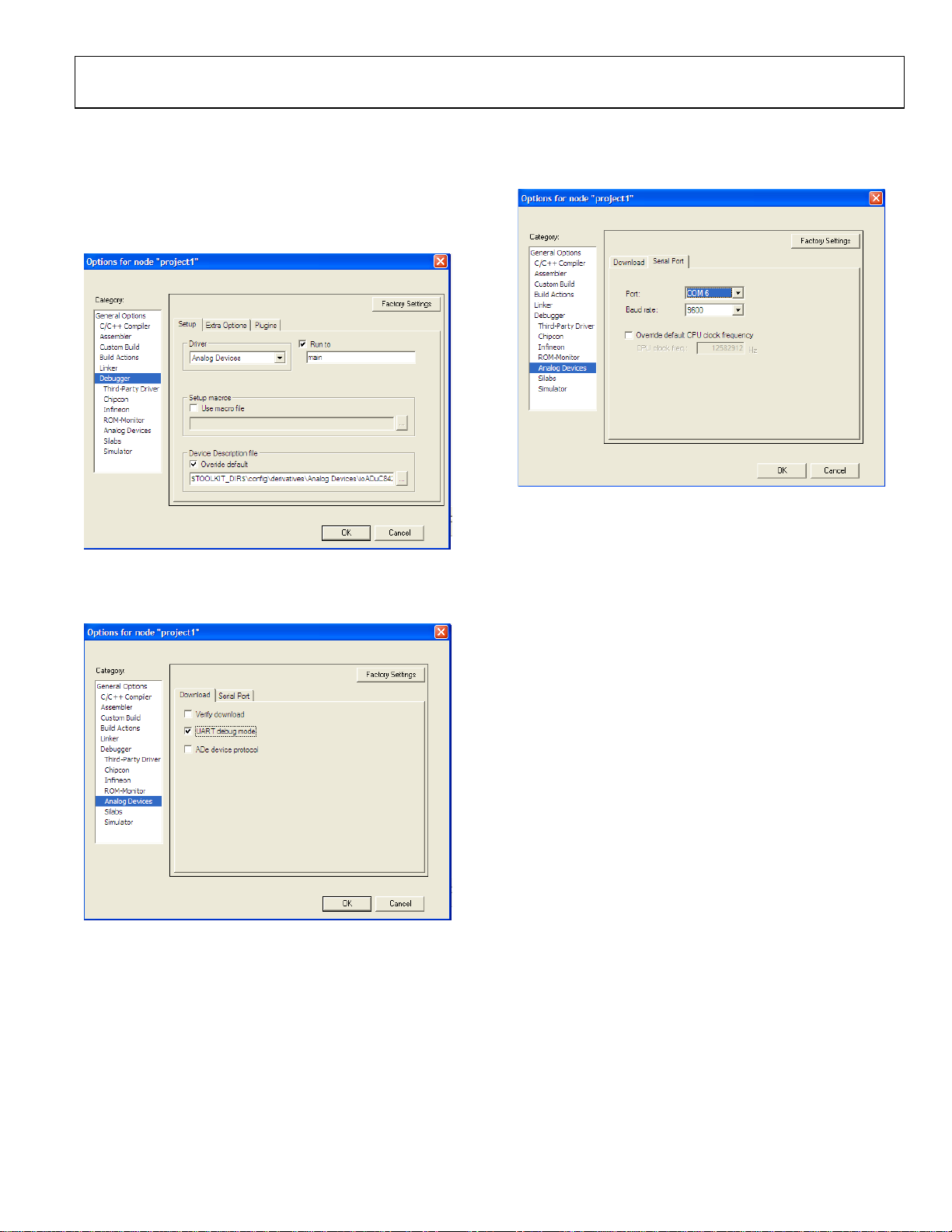
2. In the Options window, go to the Debugger section and
select the Analog Devices driver.
Figure 14. Options Window
3. Select Analog Devices and then, on the Download tab,
select UART debug mode.
08412-014
4. On the Serial Port tab, ensure that the correct COM port is
selected. Use Device Manager to identify the correct COM
port.
Figure 16.
Note that the latest 8051 tools are available for download on the
IAR company website.
KEIL/IAR LIMITATIONS WHEN USING THE USB-EA EMULATOR
Note the following limitations:
08412-016
Figure 15. Download Tab
• The Halt feature does not work with older versions of the
Keil or IAR tools. See the IAR and Keil websites for further
details and updated feature lists.
• To stop the program, breakpoints should be inserted.
08412-015
Rev. A | Page 9 of 16

UG-041 Evaluation Kit User Guide
TIMING CONSIDERATIONS WHEN DEBUGGING
As with other 8052-based parts, the watchdog on ADuC8xx
parts is not stopped during debugging. This leads to unpredictable results when the watchdog timer times out. During
initial development, it is recommended that the watchdog timer
be left disabled. For final software, Analog Devices suggests you
place code similar to the code shown below in your code.
When debugging, place a breakpoint at the second line shown,
and when this breakpoint is reached manually, using the
debugger, change the value in cWdcon to 0x00, so that the
watchdog does not start. This scheme ensures that the program
…
cWdcon = 0xe2 ; //Place parameters for watchdog in variable cWdcon.
WdWr(cWdcon); //Call assembly function to start watchdog.
…
cWdcon: //Assume interrupts not enabled.
setb WDWR
mov WDCON,r7 //Parameter cWdcon passed in r7.
ret
is debugged as it will be placed in the field. The watchdog itself
cannot be debugged by the debugger.
Other timing considerations to keep in mind are as follows:
• As with other 8052 debuggers, the user should not halt the
ADuC8xx if the part is either in idle or power-down mode.
When a break from either power saving mode occurs, the
debugger will not be able to regain control of the part and
the debug interface will crash.
• The timers on the ADuC8xx are not stopped on a break
from emulation. They will continue to run if left enabled
when breaking from emulation.
Rev. A | Page 10 of 16

Evaluation Kit User Guide UG-041
THE ADuC WASP
The Windows Analog software program (WASP) is a general
application for all MicroConverter products that allows analysis
of the analog performance of these parts. The WASP recognizes
which MicroConverter the PC is communicating with, before
automatically downloading the appropriate code.
This section serves as a tutorial to introduce both the SAR
WASP (for SAR ADC parts ADuC812, ADuC814, ADuC831,
ADuC832, ADuC841, ADuC842, and ADuC843) and the
Σ-Δ WA SP (for Σ-Δ ADC parts ADuC816, ADuC824,
ADuC834, ADuC836, ADuC845, ADuC847, and ADuC848).
The terms SAR WASP and Σ-Δ WASP relate to the same WASP
software. The software differentiates between the different
products.
After downloading the appropriate code, the WASP launches
the Acquisition window. This allows the user to configure,
control, and analyze the ADC noise performance with the
various analog and digital peripherals enabled/disabled.
1. Power up the evaluation board using the 9 V power supply.
Connect the evaluation board to your PC’s COM1 serial
port using the RS-232 dongle cable connected to the 4-way
header, J4.
2. Place the MicroConverter into serial download mode as
described in the Opening the Windows Serial Downloader
section.
3. From the Start menu, choose Programs Æ ADuC Æ
WA S P . This launches the WASP application. The WASP
executable file, WASP.exe, is located at
C:\ADuC\WASP\WASP.exe.
4. Click Download. ADuC8xx appears and the code starts to
download. A task bar indicates the download progression.
A message appears when the file is downloaded. The
program automatically runs when the download is
complete.
The Next button bypasses the download sequence and can be
used if the WASP code is already downloaded and running on
the MicroConverter. To identify the MicroConverter for the
WASP software, select the appropriate MicroConverter from
the MicroConverter Select option box and click Next.
SAR WASP
The SAR Acquisition window (see Figure 18) opens for any of
the SAR ADC MicroConverter products (ADuC812, ADuC814,
ADuC831, ADuC832, ADuC841, ADuC842 or the ADuC843).
From the Acquisition window you can
• Select the channel for converting
• Set up the ADC conversion time and sampling parameters
• Select the number of samples to acquire
• Set up voltages on the DAC channels
• Select the use of the internal reference or an external
reference device.
• Enable/disable various analog/digital peripherals
Figure 18 shows an example for converting on the temperature
sensor using the internal reference as displayed. Using the
example parameters shown, press Run. The acquired ADC
samples appear on the chart as shown on the bottom portion of
the screen for the ADuC812.
Figure 17. WASP Window
When all the samples are collected, the WASP immediately
launches the Analysis window. The histogram plot and the
ADC data analysis fields within the analysis window gives a
measure of the code distribution for the ADC input.
08412-017
Rev. A | Page 11 of 16
Figure 18. SAR Acquisition Menu
08412-018

UG-041 Evaluation Kit User Guide
Click Run to send this default configuration to the
MicroConverter device and begin the conversions. The screen
changes to configure for a single primary ADC acquisition
sequence. The results of conversion are displayed in real time.
Because the channel is configured for an internal short, ADC
conversions close to 80000h can be expected. The WASP
performs 500 ADC conversions by default and displays the
conversion results.
08412-019
Figure 19. ADC Noise Analysis Window
Click on Return to Acquisition Window in the ADC
Noise Analysis window (see Figure 19) to return to the
acquisition panel.
The functionality of the DAC(s) and general digital peripherals
can also be exercised via the options available from the WASP
front panel.
Σ-Δ WASP
The Sigma-Delta Acquisition window opens for any of the
Σ-Δ ADC MicroConverter products (ADuC816, ADuC824,
ADuC834, ADuC836, ADuC845, ADuC847, and ADuC848)
From the Acquisition window you can
• Select the channel on which you want to convert
• Set up the ADC update rate
• Select the number of samples that you want to acquire
• Set up voltages on the DAC channels
• Select the use of the internal reference or an external
reference device
• Enable/disable various analog/digital peripherals
Figure 20. Primary ADC
When all the samples are collected, the WASP immediately
launches the Analysis window. This window displays some
mathematical analysis on the ADC conversions, including rms
noise (in μV and bits) and peak-to-peak Noise (code distribution, μV and bits). The most important performance figures
are highlighted in red in Figure 21.
08412-020
Switch Configuration
Make sure that the external reference (2.5 V REF+) is connected
(S1.6 ON) for the ADuC845/ADuC847 (S4.5 ON), and that
AIN2 is biased to 2.5 V (S1.7 ON). For the ADuC845/
ADuC847, read AINCOM for Ain2 and ensure AINCOM is
biased to 2.5 V (S4.7 ON). In addition, ensure that REF− is
grounded (S1.5 ON) for the ADuC845/ADuC847 (S4.4 ON).
All other connections should be off.
By default, the WASP enables the primary ADC configured as
shown in Figure 20. In this example, the primary ADC is
converting in bipolar mode using an external reference on the
2.56 V range with internally shorted inputs AIN2 Æ AIN2
(ADuC845/ADuC847 AINCOM Æ AINCOM. The auxiliary
ADC, DAC, and Current sources are all disabled). Note that
Aux ADC and DAC are not available on the ADuC847.
Rev. A | Page 12 of 16
Figure 21. ADC Noise Analysis Window with Performance Highlights
Click Return to Acquisition Window in the Noise Analysis
window to return to the acquisition panel.
The functionality of the DAC(s) and general digital peripherals
can also be exercised via the options available from the WASP
front panel.
08412-021

Evaluation Kit User Guide UG-041
INSTALLED DOCUMENTATION AND CODE DIRECTORY
Installing the MicroConverter QuickStart Development System CD installs documentation for all the MicroConverter products at
C:\ADuC\Documentation. Review this documentation prior to starting the QuickStart Development System.
Directories for each product exist in the Documentation folder, as well as QuickStartTools and TechNotes directories. Each of the product
directories follows a similar folder structure as shown below. All Technical Notes for any of the MicroConverter products appear in the
\TechNotes directory. Check the Analog Devices website for the latest tech notes (www.analog.com/microconverter).
C:\ADuC\Documentation\ADuC8XX\
DataSheets\
ADuC8XX_Y.pdf ADuC8XX DataSheet version Y
Errata8XX_Y.pdf ADuC8XX Errata Sheet version Y
8XXqrefY.pdf ADuC8XX Quick Reference Guide version Y
EvalDocs\
8XXEvalGuide_Y.pdf ADuC8XX Eval Board Reference Guide version Y
8XXPCB_Y.pdf ADuC8XX Eval Board Schematic version Y
8XXgbrs\8XXgbrs_Y.zip ADuC8XX Eval Board Gerber files version Y.
Other\
8XXFAQs_Y.pdf ADuC8XX Frequently Asked Questions version Y
8XXgetstartedY.pdf Get Started Guide version Y
USERGuideDRAFTY.pdf Draft User guide version Y
INSTALLED CODE LOCATIONS
Installing the MicroConverter QuickStart Development System CD installs an Assembly code directory for each MicroConverter product
at C:\ADuC\Code. Product directories (such as for the ADuC832) for each MicroConverter exist with Assembly code examples.
C:\ADuC\Code\832\
ADC - - code examples for the ADC
DAC - code examples for the DAC
DualDPTR - code example for using the Dual Data Pointer
FlashEE - code example for using the Flash/EE Data Memory
I2C - code examples for I2C master and slave operation
Misc - Miscellaneous MicroConverter code example
PDown - code example demonstrating powerdown mode
PSMon - code example for the power supply monitor
SP - code example for the extended stack pointer
SPI - code examples for SPI master and slave operation
TIC - code example for the Time Interval counter
Uart - code examples for configuring the UART
WDTimer - code example for watchdog timer
Rev. A | Page 13 of 16

UG-041 Evaluation Kit User Guide
C example code is available in the C-Code directory. C-Code for the ADuC832 is in the \832 folder.
C:\ADuC\C-Code\832\
ADC - code examples for the ADC
DAC - code example for the DAC
MISC - Miscellaneous MicroConverter code example
PDOWN - code example demonstrating powerdown mode
PLL - code example for changing the core execution speed
TIC - code example for the Time Interval counter
Rev. A | Page 14 of 16

Evaluation Kit User Guide UG-041
NOTES
Rev. A | Page 15 of 16

UG-041 Evaluation Kit User Guide
NOTES
Evaluation boards are only intended for device evaluation and not for production purposes. Evaluation boards are supplied “as is” and without warranties of any kind, express,
implied, or statutory including, but not limited to, any implied warranty of merchantability or fitness for a particular purpose. No license is granted by implication or otherwise under
any patents or other intellectual property by application or use of evaluation boards. Information furnished by Analog Devices is believed to be accurate and reliable. However, no
responsibility is assumed by Analog Devices for its use, nor for any infringements of patents or other rights of third parties that may result from its use. Analog Devices reserves the
right to change devices or specifications at any time without notice. Trademarks and registered trademarks are the property of their respective owners. Evaluation boards are not
authorized to be used in life support devices or systems.
©2009 Analog Devices, Inc. All rights reserved. Trademarks and
registered trademarks are the property of their respective owners.
UG08412-0-10/09(A)
Rev. A | Page 16 of 16
 Loading...