


UG-319
Table of contents
 Loading...
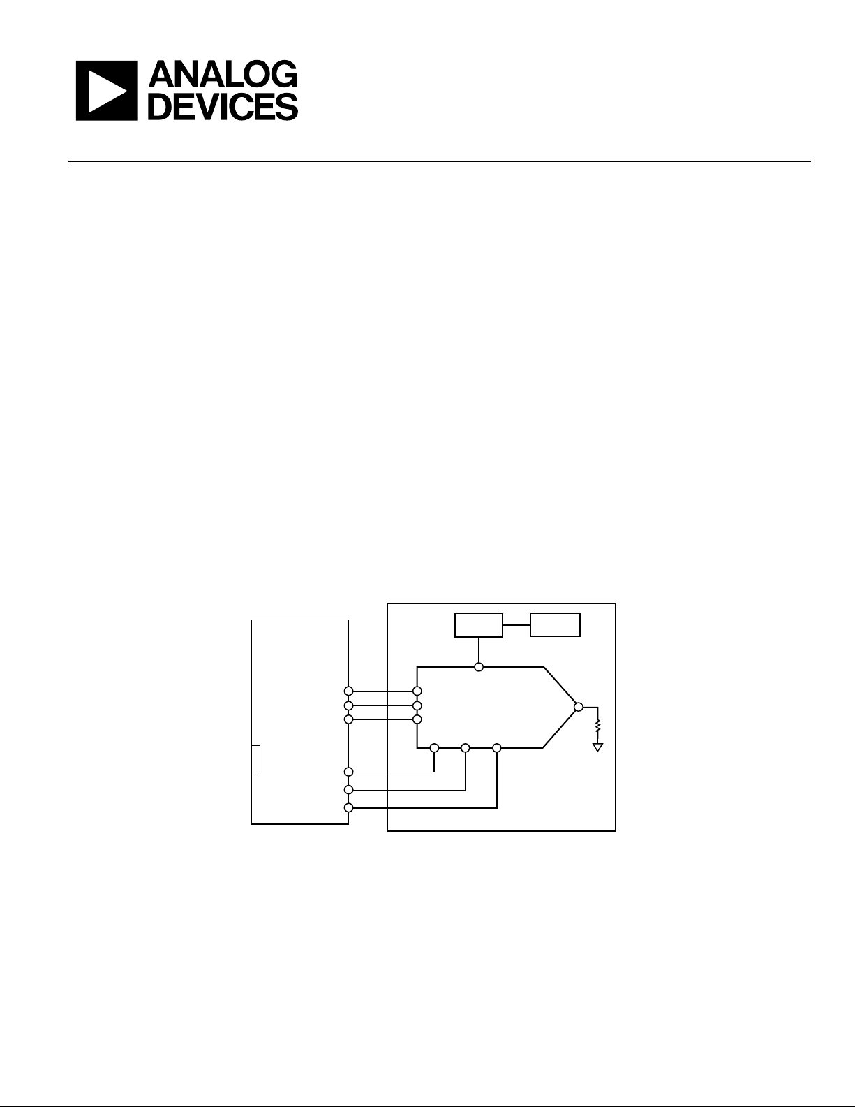
Evaluation Board User Guide
UG-319
One Technology Way • P. O . Box 9106 • Norwood, MA 02062-9106, U.S.A. • Tel : 781.329.4700 • Fax : 781.461.3113 • www.analog.com
Evaluating the AD9835 200 mW Power, 5 V,50 MHz CMOS Complete DDS
PLEASE SEE THE LAST PAGE FOR AN IMPORTANT
WARNING AND LEGAL TERMS AND CONDITIONS.
Rev. B | Page 1 of 12
FEATURES
Full featured evaluation board for the AD9835
evaluation board
Graphic user interface software for board control and
data analysis
Connector to the EVAL-SDP-CB1Z system demonstration
platform (SDP) board
Various power supply and reference link options
APPLICATIONS
DDS tuning
Digital demodulation
GENERAL DESCRIPTION
The AD9835 is a numerically controlled oscillator employing a
phase accumulator, a sine lookup table and a 10-bit digital-to-
analog converter integrated on a single CMOS chip. Modulation
capabilities are provided for phase modulation and frequency
modulation.
The EVAL-AD9835SDZ board is used in conjunction with a
EVAL-SDP-CB1Z board available from Analog Devices, Inc. The
USB-to-SPI communication to the AD9835 is completed using
this Blackfin®-based development board.
A high performance, on-board 50 MHz trimmed general oscillator
is available to use as the master clock for the AD9835 system.
Various links and SMB connectors are also available on the
EVAL-AD9835SDZ board to maximize the usability.
Complete specifications for the AD9835 are provided in the
AD9835 data sheet, available from Analog Devices, and should
be consulted in conjunction with this user guide when using the
evaluation board.
FUNCTIONAL BLOCK DIAGRAM
SCLK SDAT AFSYNC
MCLK
AD9835
PSEL1
PSEL0
FSELECT
EVAL-SDP-CB1Z
ADP3301
USB
SPI
GPIO
IOUT
MCLK XO
10177-001
Figure 1.

UG-319 Evaluation Board User Guide
Rev. B | Page 2 of 12
TABLE OF CONTENTS
Features.............................................................................................. 1
Applications....................................................................................... 1
General Description ......................................................................... 1
Functional Block Diagram .............................................................. 1
Revision History ............................................................................... 2
Evaluation Board Software.............................................................. 3
Installing the Software ................................................................. 3
Running the Software .................................................................. 4
Setting up the Digital Interface................................................... 5
Select External MCLK Frequency...............................................5
Select Frequency and Phase Registers ........................................6
Loading Frequency and Phase Registers....................................6
Power Options ...............................................................................6
Initialize, Reset, SYNC, Clear, and Sweep..................................6
Example of Operation...................................................................7
Evaluation Board Schematics and Layout......................................8
Ordering Information.................................................................... 11
Bill of Materials........................................................................... 11
REVISION HISTORY
9/11—Rev. A to Rev. B
Document Title Changed from EVAL-AD9835EB to
UG-319.................................................................................Universal
Updated Format..................................................................Universal
Changes to Features Section............................................................ 1
Replaced Figure 1 ............................................................................. 1
Deleted Introduction Section and Operating the AD9835
Evaluation Board Section ................................................................ 1
Added Applications Section and General Description Section . 1
Deleted Link and Switch Options Section and Set-Up
Conditions Section ........................................................................... 2
Deleted Evaluation Board Interfacing Section, Sockets Section,
Connectors Section, and Switches Section.................................... 3
Replaced Software Description Section with Evaluation Board
Software Section ............................................................................... 3
Replaced Figure 2 ............................................................................. 3
Deleted Table 2, Table 3, and Table 4; Renumbered
Sequentially ........................................................................................3
Added Figure 3; Renumbered Sequentially ...................................4
Changes to Table 1.............................................................................4
Changes to Figure 4...........................................................................5
Added Figure 5 and Figure 6............................................................5
Added Figure 7 to Figure 10 ............................................................6
Added Figure 11 and Figure 12 .......................................................7
Added Evaluation Board Schematics and Layout Section...........8
Changes to Figure 13.........................................................................8
Added Figure 14 ................................................................................9
Changes to Figure 15.........................................................................9
Changes to Figure 16 and Figure 17............................................. 10
Added Ordering Information Section......................................... 11
Changes to Table 2.......................................................................... 11
Evaluation Board User Guide UG-319
Rev. B | Page 3 of 12
EVALUATION BOARD SOFTWARE
INSTALLING THE SOFTWARE
The EVAL-AD9835SDZ evaluation kit includes the software
and drivers on CD. The software is compatible with Windows®
XP, Windows Vista, and Windows 7.
To install the software, follow these steps:
1. Install the software before connecting the SDP board to
the USB port of the PC.
2. Start the Windows operating system and insert the
EVAL-AD9835SDZ evaluation kit CD.
3. Download the EVAL-AD9835SDZ LabVIEW™ software.
The correct driver for the SDP board, SDPDriversNET,
should download automatically after LabVIEW is
downloaded, supporting both 32-bit and 64-bit systems.
However, if the drivers do not download automatically, the
driver executable file can also be found in the Program
Files/Analog Devices folder. Follow the on-screen
prompts to install SDPDriverNet Version 1.3.6.0.
4. After installation of the software and drivers is complete,
plug the EVAL-AD9835SDZ into the SDP board and the
SDP board into the PC using the USB cable included in
the kit.
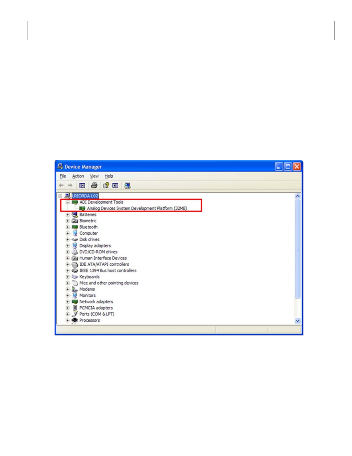
5. When the software detects the evaluation board, proceed
through any dialog boxes that appear to finalize the
installation (for example, Found New Hardware Wizard
and Install the Software Automatically).
10177-002
Figure 2. Hardware Device Manager Window with SDP Board Plugged In
UG-319 Evaluation Board User Guide
Rev. B | Page 4 of 12
RUNNING THE SOFTWARE
To run the evaluation board program, do the following:
1. Click Start/All Programs/Analog Devices/AD9835/
AD9835 Eval Board.
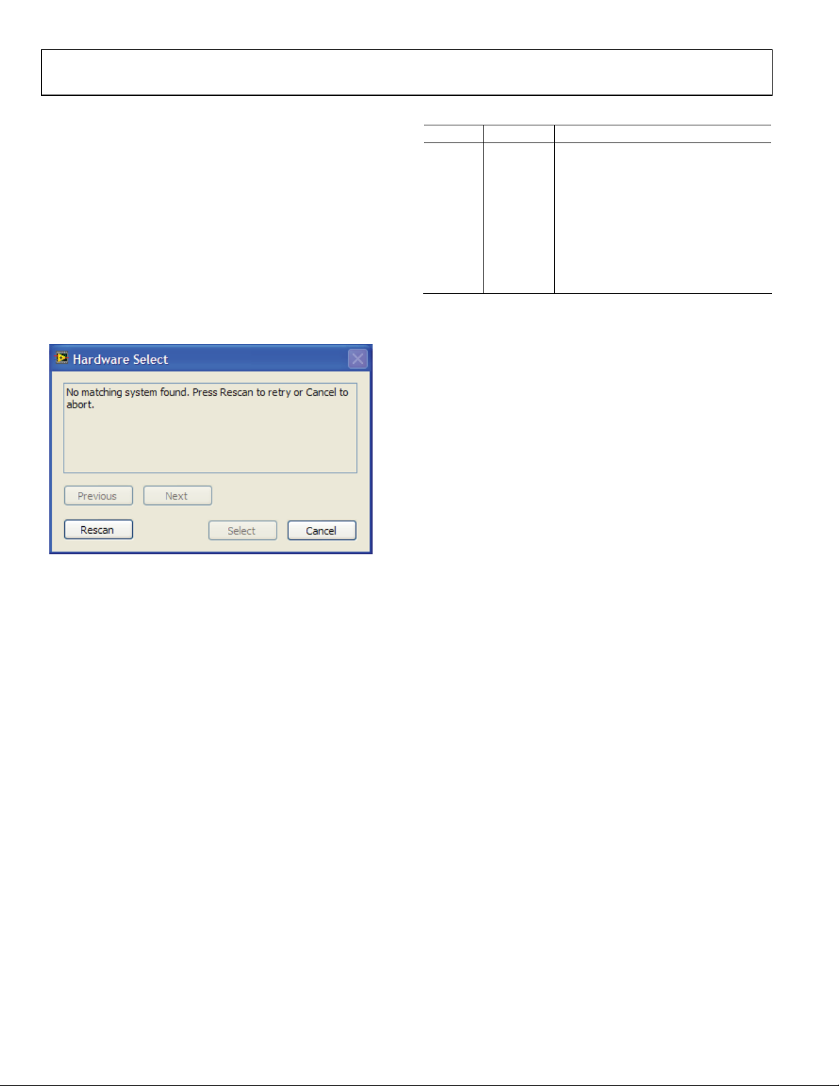
2. If the SDP board is not connected to the USB port when
the software is launched, a connectivity error displays (see
Figure 3). Simply connect the evaluation board to the USB
port of the PC, wait a few seconds, click Rescan, and follow
the instructions.
3. Ensure that all links are in their correct locations (see Ta ble 1).
The main window of the AD9835 evaluation software then
opens, as shown in Figure 4.
10177-003
Figure 3. Pop-Up Window Error
Table 1. Default Setup for Link Positions
Link No. Position Function
LK1 Connected
REFOUT is used as the reference to the
DAC by connecting REFOUT to REFIN.
LK3 B
3.3 V digital supply for the AD9835
supplied from the EVAL-SDP-CB1Z
board.
LK5 B
3.3 V analog supply for the AD9835
supplied from the EVAL-SDP-CB1Z
board.
LK6 A
On-board linear regulator selected to
supply power to the general oscillator.
Loading...