


 Loading...
Evaluation Board User Guide
UG-097
One Technology Way •P.O. Box 9106 •Norwood, MA 02062-9106, U.S.A. •Tel: 781.329.4700 •Fax: 781.461.3113 •www.analog.com
Evaluation Board for ADF4360-2 Integrated PLL and VCO Frequency Synthesizer
FEATURES
Self-contained board for generating RF frequencies Flexibility for reference input, PFD frequency, and loop
bandwidth
Accompanying software allows complete control of synthesizer functions from a PC
USB/battery-operated 9 V supplies
Typical phase noise performance of −141 dBc/Hz at 3 MHz offset Typical spurious performance of −70 dBc at 200 kHz offset
(2.0 GHz output)
GENERAL DESCRIPTION
The ADF4360-2EBZ1 evaluation board is designed to allow the user to evaluate the performance of the ADF4360-2 frequency synthesizer consisting of an integrated PLL and VCO (see Figure 1). It contains the ADF4360-2BCPZ, a USB connector, and SMA connectors for the RF outputs. Unpopulated SMA footprints are available for the power supplies, the chip enable (CE), and the external reference input. The evaluation board also contains the loop filter to complete the PLL. It can be modified as necessary for the PLL requirements of the user. A USB cable is included with the board to allow software programmability from a PC.
The package also contains a CD with Windows® software to allow quick, user-friendly programming of the synthesizer. The CD contains additional PLL data sheets, technical notes, articles, and ADIsimPLL™ V3.4 (Analog Devices, Inc., PLL simulation software). More information is available at www.analog.com/pll.
EVALUATION BOARD PHOTOGRAPH
08881-001
Figure 1.
PLEASE SEE THE LAST PAGE FOR AN IMPORTANT |
Rev. A | Page 1 of 12 |
WARNING AND LEGAL TERMS AND CONDITIONS. |

UG-097 |
Evaluation Board User Guide |
TABLE OF CONTENTS |
|
Features .............................................................................................. |
1 |
General Description ......................................................................... |
1 |
Evaluation Board Photograph......................................................... |
1 |
Revision History ............................................................................... |
2 |
Evaluation Board Hardware ............................................................ |
3 |
RF Output Stages .......................................................................... |
3 |
Evaluation Board Software Quick Start Procedures .................... |
4 |
REVISION HISTORY |
|
9/11—Rev. 0 to Rev. A |
|
Changes to Features Section and Figure 1..................................... |
1 |
Changes to Evaluation Board Hardware Section ......................... |
3 |
Added Evaluation Board Software Quick Start Procedures |
|
Section................................................................................................ |
4 |
Changes to Using the Evaluation Board Software Section.......... |
6 |
Changes to Evaluation Board Schematic Section......................... |
8 |
Changes to Bill of Materials Section ............................................ |
11 |
7/10—Revision 0: Initial Version |
|
Windows XP OS ............................................................................ |
4 |
Windows Vista OS and Windows 7 (32-Bit) OS .......................... |
5 |
Windows 7 64-Bit OS ................................................................... |
5 |
Using the Evaluation Board Software ............................................. |
6 |
Evaluation Board Schematic ............................................................ |
8 |
Ordering Information.................................................................... |
11 |
Bill of Materials........................................................................... |
11 |
Rev. A | Page 2 of 12

Evaluation Board User Guide |
UG-097 |
EVALUATION BOARD HARDWARE
The evaluation board comes with a cable to connect it to the USB port of a PC. The silkscreen and cable diagram for the evaluation board are shown in Figure 2. The board schematics are shown in Figure 9 through Figure 11.
08881-002
Figure 2. Evaluation Board Silkscreen—Top View
The board is powered from a single 9 V battery, or from the USB supply, by changing the position of Switch SW1. All components necessary for LO generation are catered for on-board. A 10 MHz TCXO from Fox Electronics provides the necessary reference input. Otherwise, an external reference signal can be connected via J3. The PLL comprises the ADF4360-2BCPZ and a passive loop filter. The VCO output from RFOUTA is available through the standard SMA Connector J1 and the complementary RFOUTB VCO output is available from J2.
Users may provide their own power supplies using the J4 and J5 connectors, as shown in Figure 2. Hardware power-down using the CE pin can be controlled by inserting an SMA connector into J6 and removing R12.
The on-board filter is a third-order, passive, low-pass filter. The filter contains three capacitors (C13, C14, and C15) plus two resistors (R10 and R11). The footprint for R10 is located on the underside of the board. The design parameters for the loop filter are for a center frequency of 2000 MHz, a PFD frequency of 200 kHz, and a low-pass filter bandwidth of 10 kHz. To design a filter for different frequency setups, use the ADIsimPLL simulation software.
RF OUTPUT STAGES
The output stage of the board contains a tuned load for the particular frequency of operation. The particular network inserted in the board is optimized for 2000 MHz operation. This consists of a 2 nH shunt inductor, a 10 pF series capacitor, and a 2 nH series inductor. If in doubt, use a 50 Ω resistor instead of the shunt inductor, a 100 pF bypass capacitor, and a series 0 Ω resistor. It is important that the same components be placed on the RFOUTA and RFOUTB lines. In addition, it is essential
that both outputs be terminated with 50 Ω loads. Otherwise, the output power is not optimum, and in some cases, the part may malfunction.
Rev. A | Page 3 of 12
UG-097 |
Evaluation Board User Guide |
EVALUATION BOARD SOFTWARE QUICK START PROCEDURES
The control software and USB drivers for EVAL-ADF4360- 2EBZ1 accompany the EVAL-ADF4360-2EBZ1 on a CD. To install the software, use the following steps:
1.Open ADF4360_Setup.msi.
2.The install wizard guides you through the installation process. The software and USB drivers will be installed in the default directory called C:\Program Files\Analog Devices\ADF4360.
The software requires Microsoft’s .NET Framework Version 2.0 or later to be installed on your machine. The installer automatically downloads the framework from the Microsoft website if you do not have this installed. If you do not have an Internet connection or have a slow connection on the PC, then you
can install the .NET framework directly from the CD. Do this by double-clicking dotnetfx.exe. Once installed, run the ADF4360_Setup.msi again.
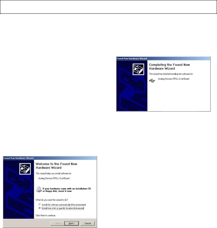
WINDOWS XP OS
Once you have installed the software, install the USB drivers. To do so, use the following steps:
1.Plug in a USB cable to the USB connector on the evaluation board. The Found New Hardware box appears. See Figure 3.
2.Choose Install from a list or specified location (Advanced).
3.Browse to C:\Program Files\Analog Devices\ADF4360.
4.Click Continue Anyway when asked about Windows Logo testing.
5.If the install was successful, the message box in Figure 4 appears.
08881-004
Figure 4. Successful Install
08881-003
Figure 3. New Hardware Wizard
Rev. A | Page 4 of 12
Loading...