


66321b
Table of contents
 Loading...
USER’S GUIDE
Agilent Technologies
Model 66319B/D, 66321B/D
Mobile Communications DC Source
Featuring programmable output resistance
(Refer to page 20 f or a br ief description of the model differences.)
Agilent Part No. 5964-8184
Microfiche No. 5964-8185
Printed in Malaysia: May, 2003

Warranty Information
CERTIFICATION
Agilent Technologies certifies that this product met its published specifications at time of shipment from the factory.
Agilent Technologies further certifies that its calibration measurements are traceable to the United States National
Bureau of Standards, to the extent allowed by the Bureau's calibration facility, and to the calibration facilities of other
International Standards Organization members.
WARRANTY
This Agilent Technologies hardware product is warranted against defects in material and workmanship for a period
of three years from date of delivery. Agilent Technologies software and firmware products, which are designated by
Agilent Technologies for use with a hardware product and when properly installed on that hardware product, are
warranted not to fail to execute their programming instructions due to defects in material and workmanship for a
period of 90 days from date of delivery. During the warranty period Agilent Technologies will, at its option, either
repair or replace products which prove to be defective. Agilent does not warrant that the operation for the software
firmware, or hardware shall be uninterrupted or error free.
For warranty service, with the exception of warranty options, this product must be returned to a service facility
designated by Agilent Technologies. Customer shall prepay shipping charges by (and shall pay all duty and taxes)
for products returned to Agilent Technologies for warranty service. Except for products returned to Customer from
another country, Agilent Technologies shall pay for return of products to Customer.
Warranty services outside the country of initial purchase are included in Agilent Technologies' product price, only if
Customer pays Agilent Technologies international prices (defined as destination local currency price, or U.S. or
Geneva Export price).
If Agilent is unable, within a reasonable time to repair or replace any product to condition as warranted, the
Customer shall be entitled to a refund of the purchase price upon return of the product to Agilent Technologies.
LIMITATION OF WARRANTY
The foregoing warranty shall not apply to defects resulting from improper or inadequate maintenance by the
Customer, Customer-supplied software or interfacing, unauthorized modification or misuse, operation outside of the
environmental specifications for the product, or improper site preparation and maintenance. NO OTHER
WARRANTY IS EXPRESSED OR IMPLIED. AGILENT TECHNOLOGIES SPECIFICALLY DISCLAIMS THE IMPLIED
WARRANTIES OF MERCHANTABILITY AND FITNESS FOR A PARTICULAR PURPOSE.
EXCLUSIVE REMEDIES
THE REMEDIES PROVIDED HEREIN ARE THE CUSTOMER'S SOLE AND EXCLUSIVE REMEDIES. AGILENT
SHALL NOT BE LIABLE FOR ANY DIRECT, INDIRECT, SPECIAL, INCIDENTAL, OR CONSEQUENTIAL
DAMAGES, WHETHER BASED ON CONTRACT, TORT, OR ANY OTHER LEGAL THEORY.
ASSISTANCE
The above statements apply only to the standard product warranty. Warranty options, extended support contacts,
product maintenance agreements and customer assistance agreements are also available. Contact your nearest
Agilent Technologies Sales and Service office for further information on Agilent Technologies' full line of Support
Programs.
2

Safety Summary
The following general safety precautions must be observed during all phases of operation of this instrument.
Failure to comply with these precautions or with specific warnings elsewhere in this manual violates safety
standards of design, manufacture, and intended use of the instrument. Agilent Technologies assumes no liability
for the customer's failure to comply with these requirements.
GENERAL
This product is a Safety Class 1 instrument (provided with a protective earth terminal). The protective features of
this product may be impaired if it is used in a manner not specified in the operation instructions.
Any LEDs used in this product are Class 1 LEDs as per IEC 825-1.
This ISM device complies with Canadian ICES-001. Cet appareil ISM est conforme à la norme NMB-001 du Canada.
ENVIRONMENTAL CONDITIONS
This instrument is intended for indoor use in an installation category II, pollution degree 2 environment. It is
designed to operate at a maximum relative humidity of 95% and at altitudes of up to 2000 meters. Refer to the
specifications tables for the ac mains voltage requirements and ambient operating temperature range.
BEFORE APPLYING POWER
Verify that the product is set to match the available line voltage, the correct fuse is installed, and all safety
precautions are taken. Note the instrument's external markings described under "Safety Symbols".
GROUND THE INSTRUMENT
To minimize shock hazard, the instrument chassis and cover must be connected to an electrical ground. The
instrument must be connect ed to the ac power mains t hrough a grounded power cable, with the ground wire firmly
connected to an electrical ground (safety ground) at the power outlet. Any interruption of the protective (grounding)
conductor or disconnection of the protective earth terminal will cause a potential shock hazard that could result in
personal injury.
ATTENTION: Un circuit de terre continu est essentiel en vue du fonctionnement sécuritaire de l'appareil.
Ne jamais mettre l'appareil en marche lorsque le conducteur de mise … la terre est d‚branch‚.
FUSES
Only fuses with the required rated current, voltage, and specified type (normal blow, time delay, etc.) should be
used. Do not use repaired fuses or short-circuited fuseholders. To do so could cause a shock or fire hazard.
Vous devrez impérativement utiliser des fusibles calibrés aux spécifications de courant, tension et type
(coupure, délai de coupure, etc ...). N'utilisez jamais de fusibles réparés et ne court-circuitez pas les supports
de fusibles. Sinon, vous risquez de provoquer un choc électrique ou un incendie.
DO NOT OPERATE IN AN EXPLOSIVE ATMOSPHERE
Do not operate the instrument in the presence of flammable gases or fumes.
DO NOT REMOVE THE INSTRUMENT COVER
Operating personnel must not remove instrument covers. Component replacement and internal adjustments must be
made only by qualified service personnel.
Instruments that appear damaged or defective should be made inoperative and secured against unintended
operation until they can be repaired by qualified service personnel.
3
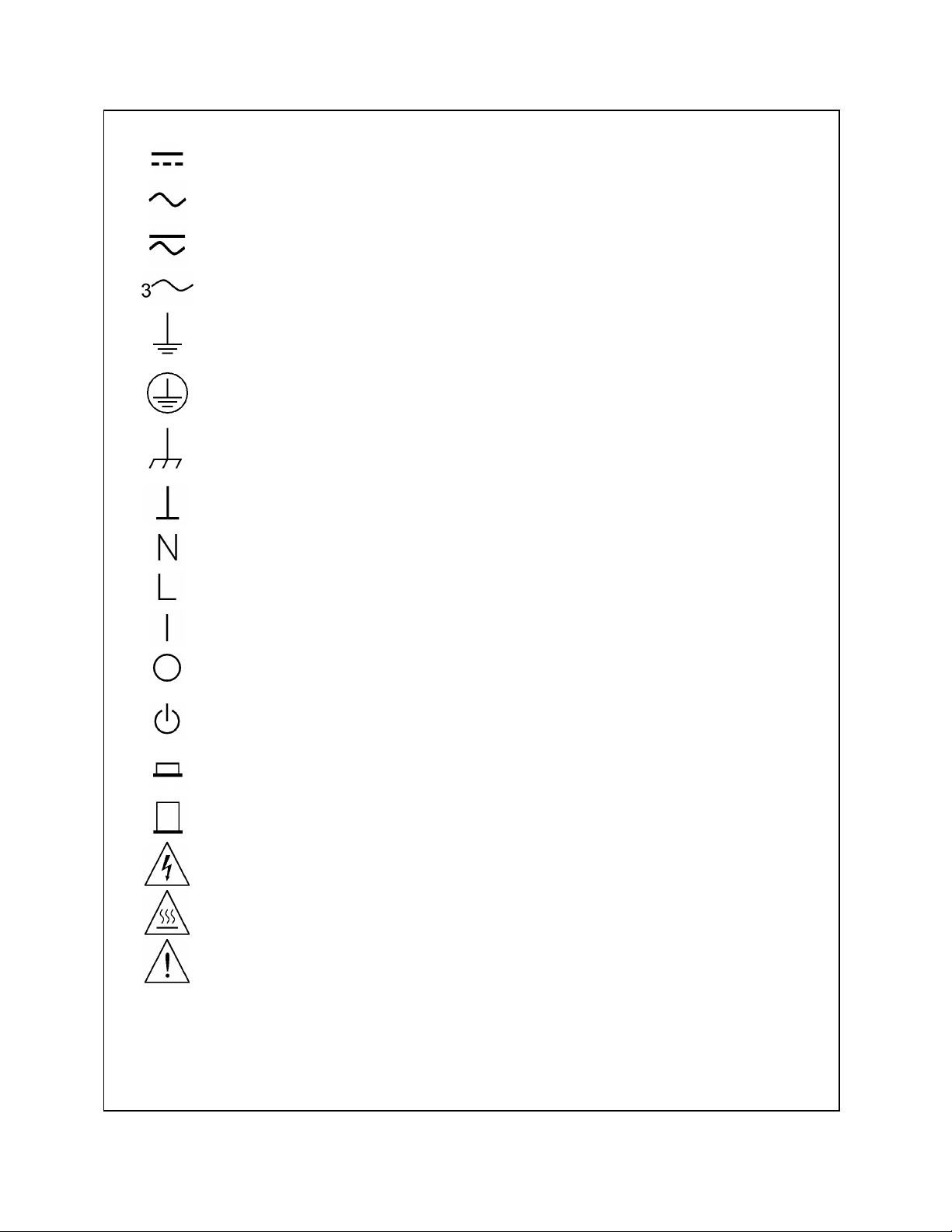
SAFETY SYMBOLS
Direct current
Alternating current
Both direct and alternating current
Three-phase alternating current
Earth (ground) terminal
Protective earth (ground) terminal
Frame or chassis terminal
Terminal is at earth potential. Used for measurement and control circuits designed to be
operated with one terminal at earth potential.
Terminal for Neutral conductor on permanently installed equipment
Terminal for Line conductor on permanently installed equipment
On (supply)
Off (supply)
Standby (supply). Units with this symbol are not completely disconnected from ac mains when
this switch is off. To completely disconnect the unit from ac mains, either disconnect the power
cord or have a qualified electrician install an external switch.
WARNING
Caution
In position of a bi-stable push control
Out position of a bi-stable push control
Caution, risk of electric shock
Caution, hot surface
Caution (refer to accompanying documents)
The WARNING sign denotes a hazard. It calls attention to a procedure, practice, or the like,
which, if not correctly performed or adhered to, could result in personal injury. Do not proceed
beyond a WARNING sign until the indicated conditions are fully understood and met.
The CAUTION sign denotes a hazard. It calls attention to an operating procedure, or the like,
which, if not correctly performed or adhered to, could result in damage to or destruction of part
or all of the product. Do not proceed beyond a CAUTION sign until the indicated conditions
are fully understood and met.
4

Declaration Page
DECLARATION OF CONFORMITY
according to ISO/IEC Guide 22 and EN 45014
Manufacturer's Name: Agilent Techno logies, Inc.
Manufacturer's Address: 140 Green Pond Road
Rockaway, New Jersey 07866
U.S.A.
declares that the Product
Product Name: a) Dynamic Measurement DC Source
b) System DC Power Supply
c) Remote Front Panel
Model Number: a) Agilent 66311B, 66311D, 66312A, 66111A, 66321B, 66321D
b) Agilent 6612B, 6611C, 6612C, 6613C, 6614C
c) Agilent 14575A
conforms to the following Product Specifications:
Safety: IEC 1010-1:1990+A1(1992)/EN61010-1:1993
EMC: CISPR 11:1990 / EN 55011:1991 - Group 1 Class B
IEC 801-2:1991 / EN 50082-1:1992 - 4 kV CD, 8 kV AD
IEC 801-3:1984 / EN 50082-1:1992 - 3 V / m
IEC 801-4:1988 / EN 50082-1:1992 - 0.5 kV Signal Lines
1 kV Power Lines
Supplementary Information:
The pro duct herewith complies with the requirements of the Low Voltage Directive
73/23/EEC//93/68/EEC and the EMC Directive 89/336/EEC and carries the CE-marking accordingly.
New Jersey May 1, 2000 ______
Location Date Bruce Krueger / Quality Manager
European Contact: Your local Agilent Technologies Sales and Service Office or Agilent Technologies GmbH,
Department TRE, Herrenberger Strasse 130, D-71034 Boeblingen (FAX:+49-7031-14-3143)
5

DECLARATION OF CONFORMITY
according to ISO/IEC Guide 22 and EN 45014
Manufacturer's Name: Agilent Techno logies, Inc.
Manufacturer's Address: 140 Green Pond Road
Rockaway, New Jersey 07866
U.S.A.
declares that the Product
Product Name: a) Mobile Communication DC Source-Dual Output
Model Number: a) Agilent 66319B, 66319D
conforms to the following Product Specifications:
Safety: IEC 1010-1:1990+A1(1992)/EN61010-1:1993
EMC: CISPR 11:1990 / EN 55011:1991 - Group 1 Class B
IEC 801-2:1991 / EN 50082-1:1992 - 4 kV CD, 8 kV AD
IEC 801-3:1984 / EN 50082-1:1992 - 3 V / m
IEC 801-4:1988 / EN 50082-1:1992 - 0.5 kV Signal Lines
1 kV Power Lines
Supplementary Information:
The pro duct herewith complies with the requirements of the Low Voltage Directive
73/23/EEC//93/68/EEC and the EMC Directive 89/336/EEC and carries the CE-marking accordingly.
New Jersey May 1, 2000 ______
Location Date Bruce Krueger / Quality Manager
European Contact: Your local Agilent Technologies Sales and Service Office or Agilent Technologies GmbH,
Department TRE, Herrenberger Strasse 130, D-71034 Boeblingen (FAX:+49-7031-14-3143)
6

Acoustic Noise Information
Herstellerbescheinigung
Diese Information steht im Zusammenhang mit den Anforderungen der
Maschinenläminformationsverordnung vom 18 Januar 1991.
* Schalldruckpegel Lp <70 dB(A)
* Am Arbeitsplatz
* Normaler Betrieb
* Nach EN 27779 (Typprüfung).
Manufacturer's Declaration
This statement is provided to comply with the requirements of the German Sound Emission Directive,
from 18 January 1991.
* Sound Pressure Lp <70 dB(A)
* At Operator Position
* Normal Operation
* According to EN 27779 (Type Test).
Printing History
The edition and current revision of this manual are indicated below. Reprints of this manual containing
minor corrections and updates may have the same printing date. Revised editions are identified by a new
printing date. A revised edition incorporates all new or corrected material since the previous printing
date.
Changes to the manual occurring between revisions are covered by change sheets shipped with the
manual. In some cases, the manual change applies only to specific instruments. Instructions provided on
the change sheet will indicate if a particular change applies only to certain instruments.
This document contains proprietary information protected by copyright. All rights are reserved. No part
of this document may be photocopied, reproduced, or translated into another language without the prior
consent of Agilent Technologies. The information contained in this document is subject to change
without notice.
Copyright 2000 Agilent Technologies, Inc. Edition 1 _______May, 2000
Update 1 ______January, 2001
Update 2 ______May, 2003
7

Table of Contents
Warranty Information 2
Safety Summary 3
Declaration Page 5
Acoustic Noise Information 7
Printing History 7
Table of Contents 8
1 - QUICK REFERENCE 11
The Front Panel - At a Glance 11
The Rear Panel - At a Glance 12
Instrument Configuration 12
Front Panel Number Entry 13
Front Panel Annunciators 14
Immediate Action Keys 14
Front Panel Menus - At a Glance 15
SCPI Programming Commands - At a Glance 16
2 - GENERAL INFORMATION 17
Document Orientation 17
Safety Considerations 18
Options and Accessories 18
Description and Model Differences 19
Option 521 Description (Agilent 66319B/D only) 23
3 - INSTALLATION 25
Installation and Operation Checklist 25
Inspection 26
Location 27
Input Connections 28
Output Connections 28
DVM Connections 36
External Protection and Trigger Input Connections 38
Digital I/O Connections 40
Computer Connections 40
4 - TURN-ON CHECKOUT 41
Checkout Procedure 41
In Case of Trouble 43
5 - FRONT PANEL OPERATION 45
Introduction 45
Front Panel Description 45
System Keys 47
Function Keys 48
Entry Keys 51
Examples of Front Panel Programming 52
6 - INTRODUCTION TO PROGRAMMING 61
External References 61
VXIplug&play Power Products Instrument Drivers 62
GPIB Capabilities of the DC Source 63
Introduction to SCPI 63
Types of SCPI Commands 64
8

Types of SCPI Messages 65
SCPI Data Formats 67
SCPI Command Completion 68
Using Device Clear 68
SCPI Conformance Information 69
7 - PROGRAMMING THE DC SOURCE 71
Introduction 71
Programming the Output 71
Triggering Output Changes 73
Making Basic Measurements 75
Making Enhanced Measurements 76
Making DVM Measurements 79
Triggered Measurements 80
Programming the Status Registers 84
Inhibit/Fault Indicator 89
8 - LANGUAGE DICTIONARY 91
Introduction 91
Calibration Commands 96
Display Commands 99
Measurement Commands 100
Output Commands 110
Status Commands 119
System Commands 123
Trigger Commands 124
Common Commands 132
A - SPECIFICATIONS 139
Specifications 139
Supplemental Characteristics 140
B - PERFORMANCE, CALIBRATION, AND CONFIGURATION 143
Introduction 143
Equipment Required 143
Measurement Techniques 144
Performance Tests 145
Constant Voltage Tests 146
Constant Current Tests 148
Resistance Tests 152
DVM Tests 152
Performance Test Equipment Form 153
Performance Test Record Form 154
Performing the Calibration Procedure 156
Performing the Configuration Procedure 161
C - ERROR MESSAGES 163
Error Number List 163
D - EXAMPLE PROGRAMS 167
Pulse Measurements 167
E - LINE VOLTAGE CONVERSION 173
9

Quick Reference
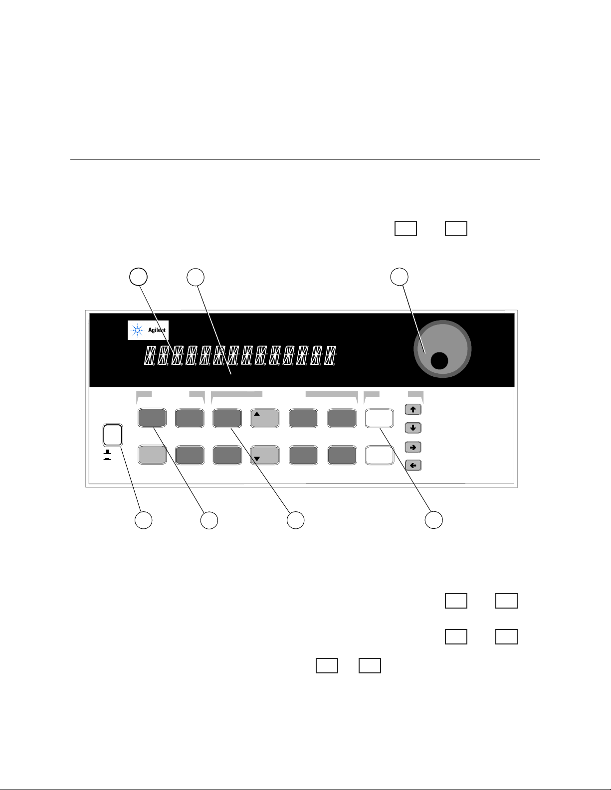
The Front Panel - At a Glance
1
1 A 14-character display
shows output measurements
and programmed values.
1 2 3
66319D DUAL OUTPUT
Mobile Communications DC Source
SYSTEM
2
6
Unr Dis OCP
Error
Address
Save
Recall
LINE
CV CC
Channel
Local
1
Off
On
2 Annunciators indicate
operating modes and status
conditions.
Cal Shift Rmt Addr Err SRQ
Prot
FUNCTION
Input
Meter
345
Protect
78 9
OV
Voltage
Current
3 Rotary control sets voltage,
current, and menu parameters.
!
"
""
Use and
to set the resolution; then adjust
the value with the knob.
ENTRY
Res
Output
.
CalOCPProt Cir
Output
On/Off
0
Cir Entry
Enter
-
Number
Enter
Backspace
! "
!!
4 5 6
4 Turns the dc
source on and off.
5 System keys:
♦ return to Local mode
♦ select output channel
♦ set GPIB address
♦ set RS-232 interface
♦ display SCPI error
codes
♦ save and recall
instrument states
♦ display firmware
revision and serial
number.
6 Function keys:
♦ enable/disable the
output
♦ select metering
functions
♦ program voltage and
current
♦ set and clear protection
functions
%
%
♦ and
$
$
$$
scroll through the front
panel menu commands.
%%
7
7 Entry keys:
♦ enter values
♦ increment or
decrement values
#
#
♦ and
&
&
&&
select front panel
menu parameters.
"
" !!!!
""
♦ and
select a digit in
the numeric entry
field.
##
11
1 - Quick Reference
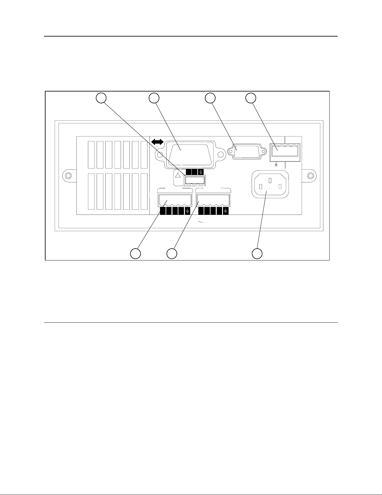
The Rear Panel - At a Glance
1 DVM inputs.
Connector plug is
removable.
WARNING:
WARNING:
2 GPIB (IEEE-488)
interface connector.
1
NO OPERATOR SERVICEABLE PARTS REFER SERVICING TO SERVICE TRAINED
FOR CONTINUED FIRE PROTECTION, USE SPECIFIED LINE
3 Used to connect the
Agilent 14575A remote
front panel display.
4 INH/FLT connector. Can
be configured for Digital I/O
and Trigger input. Connector
plug is removable.
2 3 4
+-
!
DVM
OUTPUT 2
0 - 12V / 0 - 1.5A
-S
-+
+S
-S
OUTPUT 1
0 - 15V / 0 - 3A
+S
+-
INH FLT
+-+
5 Output 2 connector
(Agilent 66319B/D only).
Connector plug is removable.
5 6
6 Output 1 connector.
Connector plug is removable.
IMPORTANT: Install this connector with
7
7 Power cord
connector (IEC 320)
its supplied sense jumpers before applying
power to the unit.
Instrument Configuration
Use the front panel Address key to configure the interface
Refer to “Front Panel Menus - At a Glance”
♦ Enter the GPIB bus address.
♦ Display the firmware revision and serial number.
12
Quick Reference - 1
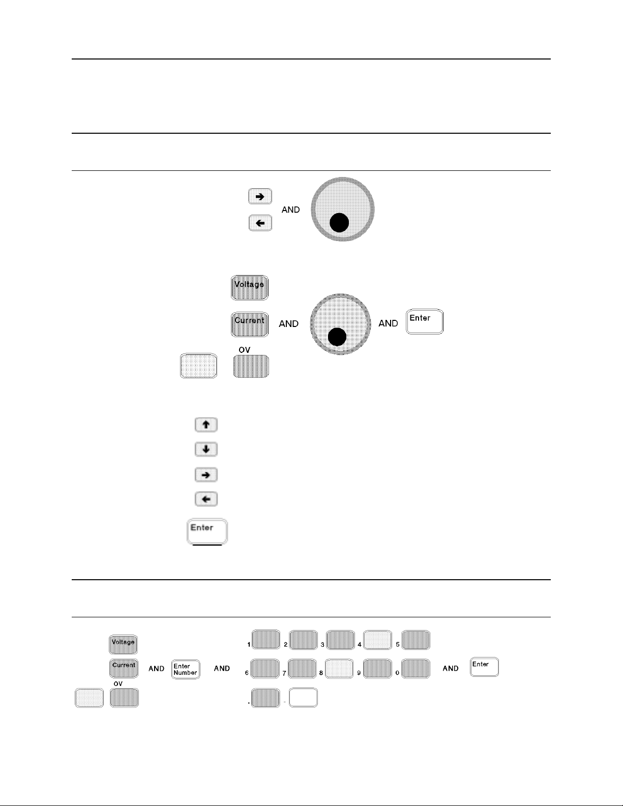
Front Panel Number Entry
Enter numbers from the front panel using one the following methods:
Use the arrow keys and knob to change voltage or current settings
NOTE: The output must be ON to see the displayed values change in Meter mode. With the
output enabled, this method changes the output voltage or current immediately.
Use the Function keys and knob to change the displayed settings
Use the arrow keys to edit individual digits in the displayed setting
Increments the flashing digit
Decrements the flashing digit
Moves the flashing digit to the right
Moves the flashing digit to the left
Enters the value when editing is complete
Use the Function keys and Entry keys to enter a new value
NOTE: If you make a mistake, use the Backspace key to delete the number, or press the Meter
key to return to meter mode.
13
1 - Quick Reference
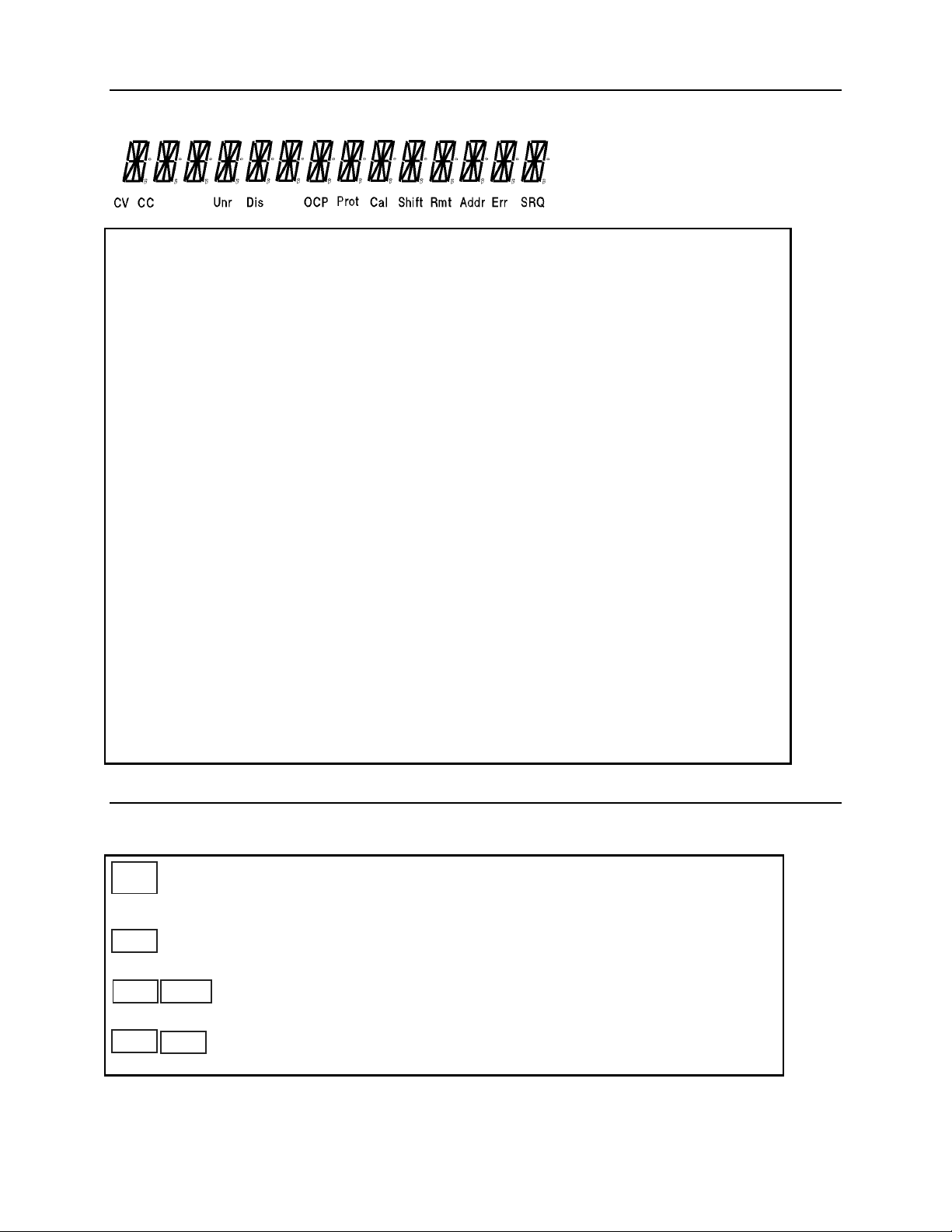
Front Panel Annunciators
CV
CC
Unr
Dis
OCP
Prot
Cal
Shift
Rmt
Addr
Err
Output 1 or output 2 is operating in constant voltage mode.
Output 1 or output 2 is operating in constant current mode.
Output 1 or output 2 is unregulated.
The output is OFF. Press the Output On/Off key to turn the output on.
The over-current protection state is ON. Press the OCP key to turn over-current
protection off.
Indicates that the output has been disabled by one of the protection features.
Press the Prot Clear key to clear the protection condition.
Calibration mode is ON. Scroll to the Cal Off command and press the Enter key
to exit the calibration mode.
The Shift key has been pressed.
The remote programming interface is active. Press the Local key to return the
unit to front panel control.
The interface is addressed to talk or listen.
There is an error in the SCPI error queue. Press the Error key to view the error
code.
SRQ
The interface is requesting service.
Immediate Action Keys
Output
Toggles the output of the selected output between the ON and OFF states.
On/Off
When coupled, turns both output channels ON or OFF.
Activates front panel control when the unit is in remote mode (unless a Lockout
Local
command is in effect).
Resets the protection circuit and allows the unit to return to its last programmed
Shift
A toggle switch that enables or disables overcurrent protection.
Prot Clr Shift
state.
OCP
14
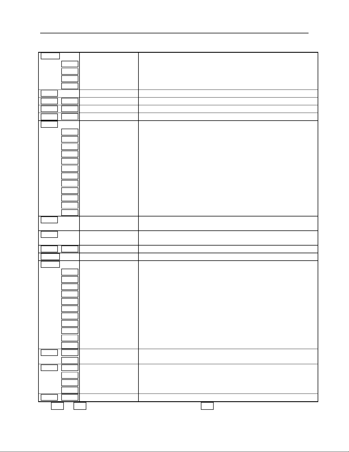
Front Panel Menus - At a Glance
Address
Recall
Shift
Shift
Meter
Voltage
Current
Shift
Protect
Output
Shift
$
$
$$
$
$
$$
$
$
$$
$
$
$$
Save Shift
Error
Channel
$
$
$$
$
$
$$
$
$
$$
$
$
$$
$
$
$$
$
$
$$
$
$
$$
$
$
$$
$
$
$$
$$$$
$
$
$$
$
$
$$
Res
$
$
$$
$
$
$$
$
$
$$
$
$
$$
$
$
$$
$
$
$$
$
$
$$
$
$
$$
$
$
$$
$
$
$$
$
$
$$
OV Shift
$
$
$$
Input
$$$$
$$$$
$$$$
Cal Shift
ADDRESS 7
LANG SCPI
REMOTE FP OFF
ROM: A.00.00
SN: US12345678
*RCL 0
*SAV 0
ERROR 0
2
5.000V 0.104A
1
12.000V 1 0.204A
1
12.500V MAX
1
1.000V MIN
1
12.330V HIGH
1
0.080V LOW
1
12.000V RMS
1
0.350A MAX
1
0.050A MIN
1
0.400A HIGH
1
0.012A LOW
1
0.210A RMS
1
12.000V DC:DVM
1
12.000V RMS:DVM
1
VOLT 12.000
2
VOLT 2.000
1
CURR 2.000
2
CURR 1.000
1
RES 1.000
OVERCURRENT
*RST
COUPLING ALL
COMP LLOCAL
PON:STATE RST
PROT:DLY 0.08
RI LATCHING
DFI OFF
DFI:SOUR OFF
PORT RIDFI
DIGIO 7
SENSE:PROT OFF
1
REL:MODE DD
VOLT:PROT 10.000
PROT:STAT ON
CURR:RANG MAX
CURR:DET ACDC
TINT 46.8
POINT 2048
CAL ON
Use and to select parameters (table shows factory defaults). Use to exit any menu.
1
Only valid for Agilent Model 66319B/D
Sets the GPIB Address
Selects language (SCPI)
Enables or disables Agilent 14575A remote front panel (ON | OFF)
Displays the firmware revision of the instrument
Displays the serial number of the instrument
Recalls the instrument state
Saves the present instrument state
Displays the number of errors in the SCPI error queue
Toggles the display between output 1 and output 2 (output 2 shown)
Measures the output voltage and current (output 1 shown)
Measures the peak output voltage
Measures the minimum output voltage
Measures the high level of a voltage pulse waveform
Measures the low level of a voltage pulse waveform
Measures the rms voltage
Measures the peak output current
Measures the minimum output current
Measures the high level of a current pulse waveform
Measures the low level of a current pulse waveform
Measures the rms current
Measures the dc voltage on the DVM input
Measures the rms voltage on the DVM input
1
1
Sets the voltage of output 1 on all models
Sets the voltage of output 2
2
Sets the current limit of output 1 on all models
Sets the current limit of output 2
2
Sets the resistance of output 1 on all models
Protection status (example shows overcurrent tripped)
Places the dc source in the factory-default state
Couples or decouples output 1 and output 2 (NONE or ALL) 1
Sets the output compensation (HREMOTE, LREMOTE, HLOCAL or LLOCAL)
Select the power-on state command (RST or RCL0)
Sets the output protection delay in seconds
Sets the remote inhibit mode (LATCHING, LIVE, or OFF)
Sets the discrete fault indicator state (ON or OFF)
Selects the DFI source (Q UES, OPER, ESB, RQS, or OFF)
Sets the output port functions (RIDFI, DIGIO, or TRIGGER)
Sets and reads the I/O port value (0 through 7)
Enables or disables the open sense lead detect circuit (ON or OFF)
Sets the relay mode for Option 521 units (DD, HD, DH, or HH) (output 1 shown)
Sets the programmable voltage limit for output 1
Enables or disables overvoltage protection for output 1 (ON or OFF)
Sets the current range (3A, 1A, 0.02A, or AUTO)
Sets the current measurement detector (ACDC or DC)
Sets the time interval for a front panel measurement in seconds
Sets the buffer size for a front panel measurement
Accesses calibration menu (See Appendix B)
2
Only valid for Agilent Model 66321D/66319D
Meter #### &&&&
Quick Reference - 1
15

1 - Quick Reference
SCPI Programming Commands - At a Glance
NOTE: Some [optional] commands have been included for clarity. Refer to chapter 8 for a
complete description of all programming commands.
ABORt SENSe
CALibrate :CURRent :RANGe <n>
:CURRent [:POSitiv e] :DETector ACDC | DC
:MEASure :LOWRange :FUNCtion “VOLT” | “CURR” | "DVM"
:R3 :LEAD :STATus?
:AC :PROTection :STATe <bool>
:CURRent2
:DATA <n> :POINts <n>
:DATE <date> :TINTerval <n>
:DVM
:LEVel P1 | P2 [SOURce:]
:PASSword <n> CURRent <n>
:RESistance :TRIGgered <n>
:SAVE :PROTection :STATe <bool>
:STATe <bool> [, <n>] CURRent2 <n>
:VOLTage [:DC] :TRIGgered <n>
:VOLTage2
DISPlay :FUNCtion RIDF | DIG | TRI G
<bool> RESistance <n>
:CHANnel <channel>
:MODE NORMal | TEXT VOLTage <n>
:TEXT <display_string> :TRIGgered <n>
FORMat :PROTection <n>
[:DATA] ASCII | REAL [,length] :STATe <bool>
:BORDer NORM | SWAP VOLTage2 <n>
INITiate :TRIGgered <n>
:SEQuence[1|2] STATus
:NAME TRANsient | ACQuire :PRESet
:CONTinuous :SEQuence[1], <bool> :OPERation [:EVENt]?
:NAME TRANsient, <bool> :CONDition?
INSTrument :ENABle <n>
:COUPling:OUTPut:STATe NONE | ALL
MEASure :PTRansition <n>
:CURRent2 [:DC]?
:VOLTage2 [:DC]?
MEASure | FETCh :ENABle <n>
:ARRay :CURRent? :NTRansition <n>
:VOLTage? :PTRansition <n>
[:CURRent] [:DC]? SYSTem
:ACDC? :ERRor?
:HIGH? :LANGuage SCPI
:LOW? :VERSion?
:MAX? TRIGger
:MIN? :SEQuence2| :ACQuire [:IMMediate]
:DVM [:DC]?
:ACDC?
:VOLTage [:DC]? :VOLTage <n>
:ACDC? :HYSTeresis:CURRent <n>
:HIGH? :DVM <n>
:LOW? :VOLTage <n>
:MAX? :LEVel :CURRent <n>
:MIN? :DVM <n>
OUTPut [1|2] :VOLTage <n>
<bool> :SLOPe :CURRent POS | NEG | EITH
:COMPensation :MODE LLOCAL | HLOCAL | LREMOTE | HREMOTE :DVM POS | NEG | EITH
:DFI <bool> :VOLTage POS | NEG | EITH
:SOURce QUES | OPER | ESB | RQS | OFF :SOURce BUS | INT | EXT
:PON :STATe RST | RCL0 [:SEQuence1| :TRANsient][:IMMediate]
:PROTection :CLEar :SOURce BUS
:DELay <n> :SEQuence1 :DEFine TRANsient
:RELay :MODE DD | HD | DH | HH
:RI :MODE LATCHing | LIVE | OFF
1
Only valid for Agi lent 66319B/D 2 Only valid for 66321D/ 66319D
1
:SWEep :OFFSet :POINts <n>
2
:WINDow :TYPE “HANN” | “RECT”
1
1
1
DIGital :DATA <n>
1
:TRIGgered <n>
1
1
:NTRansition <n>
1
:QUEStionable [:EVENt]?
1
:CONDition?
2
:COUNt :CURRent <n>
2
:DVM <n> 2
1
:SEQuence2 :DEFine ACQuire
1
2
2
2
16

2
General Information
Document Orientation
This manual describes the operation of the Agilent Model 66321B/D Mobile Communications and the
Agilent Model 66319B/D Dual Output DC Source. Agilent Models 66321D and 66319D have an
additional DVM measurement input on the rear panel. Unless otherwise noted, all models will be
referred to by the description "dc source" throughout this manual.
The following Getting Started Map will help you find the information you need to complete the specific
task that you want to accomplish. Refer to the table of contents or index of each guide for a complete list
of the information contained within.
Getting Started Map
Task Where to find information
Quick Reference Section
General information
Model differences
Capabilities and characteristics
Installing the unit
Line connections
Computer connections
Load connections
Checking out the unit
Verifying proper operation
Using the front panel
Calibrating the unit
Using the front panel
Front panel keys
Front panel examples
Using the programming interface
GPIB interface
Programming the unit using SCPI commands
SCPI commands
SCPI programming examples
SCPI language dictionary
Installing the VXIplug&play instrument driver
NOTE: The driver must be installed on your pc to access
the on-line information. Drivers are available on the web
at www.agilent.com/find/drivers.
Chapter 1
Chapter 2
Chapter 3
Chapter 4
Chapter 5
Chapter 6
Chapters 7 and 8
Chapter 6
17

2 - General Informat ion
Safety Considerations
This dc source is a Safety Class 1 instrument, which means it has a protective earth terminal. That
terminal must be connected to earth ground through a power source equipped with a ground receptacle.
Refer to the Safety Summary page at the beginning of this guide for general safety information. Before
installation or operation, check the dc source and review this guide for safety warnings and instructions.
Safety warnings for specific procedures are located at appropriate places in the guide.
Options and Accessories
Table 2-1. Options
Option Description
100
120
220
230
8ZJ Delete instrument feet option
004 Output compensation is factory set to HRemote mode for best transient response.
AXS1 Rack mount kit for two side-by-side units of equal depth. Consists of:
1CM1 Rack mount kit for one unit (p/n 5062-3972)
521 Solid-state relays to connect and disconnect the output of the dc source (Agilent 66319B/D
052 Device characterization software for displaying current and voltage measurements.
1
Support rails are required when rack mounting units. Use E3663A support rails for Agilent rack cabinets. If you are
using non-Agilent rack cabinets, contact the rack manufacturer to obtain support rails for your cabinet.
GPIB cables 1.0 meter (3.3 ft) Agilent 10833A
2.0 meters (6.6 ft) Agilent 10833B
4.0 meters (13.2 ft) Agilent 10833C
0.5 meters (1.6 ft) Agilent 10833D
87−106 Vac, 47−63 Hz
104−127 Vac, 47−63 Hz
191−233 Vac, 47−63 Hz
207−253 Vac, 47−63 Hz
(Refer to chapter 3, under "Output Compensation" for more information)
Lock-link kit (p/n 5061-9694) and Flange kit (p/n 5062-3974)
only). Provides the ability to either Hot-switch or Dry-switch the solid state relays.
Table 2-2. Accessories
Item Part Number
Rack mount with slide - for two side-by-side units of different depths 5062-3996; 1494-0015
Rack mount - for two side by side units of different depths 5062-3996
Rack mount with slide - for one unit 5062-3996; 1494-0015;
5062-4022
18

General Information - 2
Description and Model Differences
Agilent 66321B
The Agilent 66321B Mobile Communications DC Source is a high performance dc power source that
provides peak current sourcing and rapid, basic measurements in a compact, half-rack box. It is designed
to simplify the testing of digital wireless communications products. Excellent voltage transient response
characteristics prevent test interruptions due to triggering of low voltage phone shutdown. The 15 volt
source and 5A peak current capability provides compatibility with a number of communications
standards, including: GSM, CDMA, TDMA, PCS, DECT, TERA, PHS, NADC, PHS, and others.
Additional capabilities include fast dynamic measurement and analysis of voltage and current waveforms
combined with precision current measurement. This lets you characterize cellular phone current drain
under all operating conditions. Programmable output resistance lets you emulate the effects of the
internal resistance of a battery. Negative resistance programming lets you compensate for voltage drops
that occur between the remote sense points and the phone terminals. Programmable output compensation
lets you optimize the transient response for various wire lengths and phone capacitances. Figure 2-1
describes the output characteristic of the dc source.
Agilent 66319B
The Agilent 66319B Mobile Communications DC Source includes all of the capabilities of the Agilent
66321B with the addition of a second, electrically-isolated output. Figure 2-2 describes output
characteristic of this second output, which is primarily used to provide voltage or current for a charger
input on the device under test. The second output has all of the basic programmable features as the main
output, with the exception of the waveform measurement capability, open sense lead detect capability,
resistance programming, overvoltage protection, and low and middle current measurement ranges.
Agilent 66321D and 66319D
The Agilent 66321D and 66319D Mobile Communications DC Sources also contain an auxiliary DVM,
with input terminals located on the rear panel. This provides limited, low voltage dc and ac measurement
capability, which can be used to monitor test point voltages on the unit under test as well as on the test
fixture. The common mode voltage range is from −4.5 Vdc to +25 Vdc relative to the minus terminal of
output 1. The DVM is programmable from the front panel of the instrument as well as remotely using
SCPI programming commands.
Common Features
♦ Voltage, current, and resistance control with 12-bit programming resolution on output 1.
! 3-ampere current source capability (up to 5 amperes for 7 milliseconds).
! Output resistance programming capability from −40 milliohm to 1 ohm.
! Four output compensation modes for a variety of wiring configurations.
♦ Extensive measurement capability on output 1
! dc voltage and current.
! rms and peak voltage and current.
! Three-range current measurement capability up to approximately 7.0 amperes.
! 16-bit measurement resolution.
19

2 - General Informat ion
! Triggered acquisition of digitized current and voltage waveforms
! External measurement trigger input on units with firmware revision A.03.01 and up
♦ Open sense lead protection on output 1.
♦ Automatic overvoltage protection tracking.
♦ Over-temperature, RI/DFI protection features, programmable voltage limit and current limit.
♦ Non-volatile state storage and recall with SCPI command language.
♦ User-configurable power-on/reset settings (see Appendix B).
Table 2-3. Agilent Model Differences
Item 66321B 66321D 66319B 66319D 66311B/D
0 - 1 A range current
measurements (output 1)
0 - 20 mA range current
measurements (output 1)
4-mode output compensation
(output 1)
Auxiliary output (output2) NO NO YES YES NO YES
External DVM input NO YES NO YES 66311D only 66309D only
Output resistance
programming (output 1)
Automatic overvoltage
tracking (output 1)
RS-232 interface NO NO NO NO YES NO
Compatibility commands NO NO NO NO YES NO
External measurement trigger
2
input
1
Earlier models not covered in this manual (order manual p/n 5964-8125)
2
Available only on units with firmware revision A.03.01 and up
YES YES YES YES NO NO
YES YES YES YES YES YES
YES YES YES YES 2 modes 2 modes
YES YES YES YES NO NO
YES YES YES YES NO NO
YES YES YES YES NO NO
1
66309B/D1
Front Panel Controls
The front panel has both rotary and keypad controls for setting the output voltage and current. The panel
display provides digital readouts of a number of output measurements. Annunciators display the
operating status of the dc source. System keys let you perform system functions such as setting the GPIB
address and recalling operating states. Front panel Function keys access the dc source function menus.
Front panel Entry keys let you select and enter parameter values. Refer to chapter 5 for a complete
description of the front panel controls.
Remote Programming
NOTE: The dc sources described in this manual can only be programmed using the SCPI
programming language.
The dc source may be remotely programmed via the GPIB bus. GPIB programming is with SCPI
commands (Standard Commands for Programmable Instruments), which make dc source programs
compatible with those of other GPIB instruments. Dc source status registers allow remote monitoring of a
wide variety of dc source operating conditions. Refer to chapters 6 and 7 for more information. Chapter 8
is a language dictionary of all SCPI commands that can be used to program the dc source.
20
General Information - 2
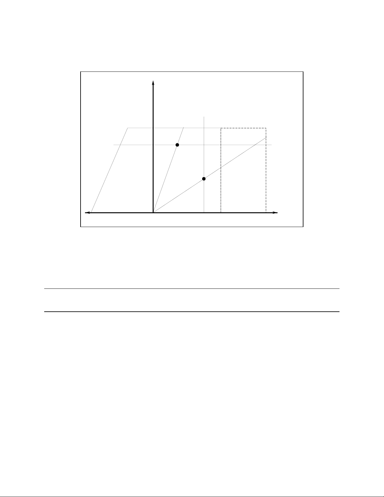
Output 1 Characteristic
The dc source's main output (output 1) characteristic is shown in the following figure. The main output of
the dc source may be adjusted to any value within the boundaries shown.
Output
Voltage
ISET
-1.2A
15V
1
e
n
i
l
d
a
o
l
e
v
i
t
s
i
s
e
r
V
C
C
C
o
l
e
v
i
t
s
i
s
e
r
2
e
n
i
l
d
a
Peak Current
capability for up
to 7 ms shown
by dotted lines
3A
5A
+-
Output
Current
-2.8A
VSET
0
Figure 2-1. Dc Source Output 1 Characteristic
The dc source is capable of providing a constant dc output of 15 volts with up to 3 amperes of current. It
is capable of sourcing peak currents of up to 5 amperes -- provided the peak current pulse does not
exceed 7 milliseconds, and the average current requirement does not exceed 3 amperes. If the unit
attempts to draw current for longer than 7 milliseconds, the current limit amplifier will limit the current
to a maximum of 3.0712 amps. The peak current capability is illustrated by the dotted line in Figure 2-1.
NOTE: To source up to 5 amperes of current for up to 7 milliseconds, the current limit must
be programmed for greater than 3 amperes (up to a maximum of 3.0712 A).
The dc source can operate in either constant voltage (CV) or constant current (CC) over the rated output
voltage and current. Although the dc source can operate in either mode, it is designed as a constant
voltage source. This means that the unit turns on in constant voltage mode with the output voltage rising
to its Vset value. There is no command for constant current operation. The only way to turn the unit on in
constant current mode is by placing a short across the output and then enabling or turning the output on.
Note that the dc source cannot be programmed to operate in a specific mode. After initial turn-on, the
operating mode of the unit will be determined by the voltage setting, current setting, and the load
resistance. In figure 2-1, operating point 1 is defined by the load line traversing the positive operating
quadrant in the constant voltage region. Operating point 2 is defined by the load line traversing the
positive operating quadrant in the constant current region.
Figure 2-1 also shows a single range − two quadrant capability. This means that the dc source is capable
of sourcing as well as sinking current over the output voltage range from zero volts to the rated voltage.
This negative current sinking capability provides fast downprogramming of the output of the dc source. It
can also be used to sink current from a battery charger, thus providing battery charger test capability. The
negative current is not programmable, and varies linearly from approximately 1.2 amperes at the full
rated voltage, to approximately 2.8 amperes at zero output voltage.
21

2 - General Informat ion
NOTE: Operating the dc source beyond its output ratings may cause the output to become unregulated.
This is indicated by the UNR annunciator on the front panel. The output may also become
unregulated if the ac line voltage drops below the minimum rating specified in Appendix A.
Programmable Output Resistance
Programmable output resistance lets you emulate the internal resistance of a cell phone battery, which
causes the voltage at the phone to drop as the phone draws more current. Different types of phone
batteries have different internal resistance values, which typically fall in a range of several hundred
milliohms. The internal resistance of a phone battery also changes with age and the number of times the
battery is recharged. Therefore, to evaluate the performance of a cell phone using various battery
characteristics, use this feature to specify a desired battery resistance.
Alternatively, programmable output resistance can be used to keep the voltage at the phone terminals as
constant as possible. In this case, you may program a negative output resistance. This compensates for
any additional voltage drop in the load leads between the remote sense points and the phone terminals
(see Figure 3-4). In phone test fixtures, the cell phone terminals may be located up to 50 centimeters
away from the connector where the remote sense terminals of the dc source are connected. This results in
a small voltage drop in the wires between the remote sense terminals and the phone terminals. If it is
critical that the steady-state voltage at the phone terminals be equal to the programmed voltage of the dc
source, a small negative output resistance can be programmed to compensate for this voltage drop.
Output 2 Characteristic
As shown in the following figure, Agilent 66319B/D units have a second output rated at 12 V and 1.5A.
The second output has all of the primary programmable features as the main output, with the exception of
the waveform measurement capability, the open sense lead detect capability, overvoltage protection, and
low current range.
Output
Voltage
+12V
Peak Current
capability for up
to 1 ms shown
by dotted lines
3.0A
+
Output
Current
0
Figure 2-2. Output 2 Characteristic
1.5A
Tables A-1 through A-3 document the specifications and supplemental characteristics of the Agilent dc
sources documented in this manual.
22

General Information - 2
Option 521 Description (Agilent 66319B/D only)
Option 521 consists of the following enhancements to the output capabilities of Agilent models
66319B/66319D:
♦ Solid-state relays to connect and disconnect the output of the dc source.
The relays are available on the output and sense terminals of outputs 1 and 2. When the solid state
relays are open, the output impedance is effectively raised to about 500k ohms for output 1, and
about 200k ohms for output 2. Note that the relays open only in response to an Output OFF
command.
♦ The ability to either Hot switch or Dry switch the solid state relays.
With Hot switching, the relays control the on/off characteristics of the voltage at the output
terminals. With Dry switching, the power mesh controls the on/off characteristics of the voltage at
the output terminals. In general, Hot switching activates the relays when current is flowing through
them. Dry switching activates the relays when no current is flowing through them. You can specify
different relay options for the Output ON and Output OFF commands. The following table describes
the actions that occur based on the relay mode selection in response to the ON or OFF commands.
Table 2-5. Option 521 Relay Modes
Relay Mode Output ON Output OFF
Dry (D)
Hot (H)
1. Closes the output relay
2. Closes the sense relay
3. Programs the output
1. Programs the power mesh
2. Closes the output relay
3. Closes the sense relay
1. Downprograms the output
2. Opens the sense relay
3. Opens the output relay
1. Opens the sense relay
2. Opens the output relay
3. Downprograms the power mesh
The relay modes are stored in non-volatile memory. The last selected mode will be restored when the
unit is turned on. When shipped from the factory, the relay mode for both output 1 and output 2 is set
to Output ON Hot, Output OFF Hot (HH). The *RST command has no effect on the relay mode.
NOTES: Even with open sense lead detection enabled, the dc source does not check for open
sense leads when output 1 is enabled if the Output ON relay mode is set to Hot.
On output 1 and output 2, with the Output OFF relay mode set to Hot, any external
output capacitors will not be downprogrammed or discharged. This is because the output
relay opens prior to the downprogramming of the power mesh.
With either output 1 or output 2 disabled, the output voltage readback will not be correct.
This is because the sense relay is open, effectively breaking the readback path. The
voltage readback will be a small negative number.
Table 2-6. Option 521 Factory Settings
Output Coupling
(outputs not coupled)
Output Sense Protection
Output Compensation
Output 1 Relay Mode
Output 2 Relay Mode
None
Off
HRemote
HH
HH
23


3
Installation
Installation and Operation Checklist
Check the Output Compensation
# Check that the output compensation of the dc source is appropriate for your application. Refer to
“Output Compensation” in this chapter.
HRemote mode provides the best transient response and can be used with phones having input
capacitances from 5µF to 12000µF. Note that if the last two digits on the front panel display are fluctuating
when the phone is in standby, you may want to set the output compensation to a different mode.
LLocal mode offer the best stability with the lowest bandwidth.
Check the Phone Connections
# If you ARE remote sensing, are the + and −−−− sense leads connected ONLY at the test fixture and
within 50 cm of the phone contacts? For best performance, the distance from sense lead termination to
the phone contacts should be as short as possible. Refer to “Remote Sense Connections” in this chapter.
# If you are NOT remote sensing, are the sense jumpers installed in the output connector? Ensure
that the output connector plug is installed in the unit with its supplied sense jumpers in place. Without
sense jumpers, the unit goes into a protect state with the output disabled.
Check the Operating Settings and Conditions
# Are you able to communicate remotely with the dc source? If not, check that the address is set
correctly. Refer to "GPIB Interface" in chapter 2.
# Is the Prot or Err annunciator on the front panel on? If yes, clear the fault condition before
continuing. Refer to “Clearing Output Protection” in chapter 5.
# Is the Overvoltage circuit shutting the unit down? If yes, you can disable the overvoltage circuit.
Refer to “Clearing Output Protection” in chapter 5.
# Is the output load regulation of the unit excessive? If yes, make sure that the output resistance of the
unit is set to zero ohms. Refer to “Output Resistance” in chapter 5.
Check the Measurement Settings
# Are the front panel readings unstable? If yes, check that the front panel sampling rate is correct.
check the setting of the output compensation. Refer to “Making Front Panel Measurements” in chapter 5
and “Output Compensation” in this chapter.
Also
# Are you measuring dynamic output currents? If yes, check that the current detector is set to ACDC.
Refer to “Making Front Panel Measurements” in chapter 5.
# Are you measuring output currents < 1 A or < 20 mA? If yes, check that the current range is set
appropriately. Refer to “Making Front Panel Measurements” in chapter 5.
25

3 - Installation
Inspection
Damage
When you receive your dc source, inspect it for any obvious damage that may have occurred during
shipment. If there is damage, notify the shipping carrier and the nearest Agilent Sales and Support Office
immediately. The list of Agilent Sales and Support Offices is at the back of this guide. Warranty
information is printed in the front of this guide.
Packaging Material
Until you have checked out the dc source, save the shipping carton and packing materials in case the unit
has to be returned. If you return the dc source for service, attach a tag identifying the owner's name and
address, the model number, and a brief description of the problem.
Items Supplied
The following user-replaceable items are included with your dc source. Some of these items are installed
in the unit.
Table 3-1. Items Supplied
Item Part Number Description
Power Cord contact the nearest Agilent
Sales and Support Office
Digital I/O
connector
Output
connector
DVM
connector
Sense jumpers 8120-8821 Jumpers that insert into output connector for local
Line Fuse 2110-0638
Feet 5041-8801 feet for bench mounting
User's Guide 5964-8125 This manual. Contains installation, checkout, front
1252-1488 4-terminal digital plug for connecting digital I/O leads.
0360-2604 5-terminal output plug for connecting load and sense
1252-8670 3-terminal plug for DVM connections (66319B/D)
2110-0773
A power cord appropriate for your location.
The connector installs in the back of the unit.
leads. This connector installs in the back of the unit.
sensing. Connect +s to +, and −s to −.
3.15 AT (time delay) for 100/120 Vac operation
1.6 AT (time delay) for 220/230 Vac operation
panel, and programming information.
Cleaning
Use a dry cloth or one slightly dampened with water to clean the external case parts. Do not attempt to
clean internally.
WARNING: To prevent electric shock, unplug the unit before cleaning.
26
Installation - 3
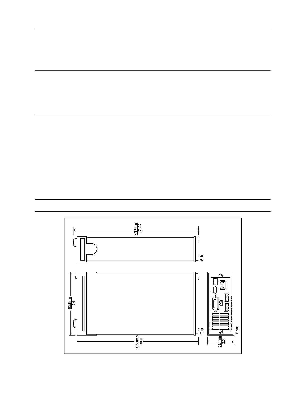
Location
Figure 3-1 gives the dimensions of your dc source. The dc source must be installed in a location that
allows sufficient space at the sides and back of the unit for adequate air circulation (see Bench
Operation).
NOTE: This dc source generates magnetic fields that may affect the operation of other
instruments. If your instrument is susceptible to operating magnetic fields, do not locate
it in the immediate vicinity of the dc source. Typically, at three inches from the dc
source, the electromagnetic field is less than 5 gauss. Many CRT’s, such as those used in
computer displays, are susceptible to magnetic fields much lower than 5 gauss. Check
susceptibility before mounting any display near the dc source.
Bench Operation
Do not block the fan exhaust at the rear of the unit.
A fan cools the dc source by drawing air in through the sides and exhausting it out the back. Minimum
clearances for bench operation are 1 inch (25 mm) along the sides.
Rack Mounting
The dc source can be mounted in a standard 19-inch rack panel or cabinet. Table 2-1 documents the part
numbers for the various rack mounting options that are available for the dc source. Installation
instructions are included with each rack mount option.
NOTE: Support rails or an instrument shelf is required when rack mounting units.
Figure 3-1. Outline Diagram
27

3 - Installation
Input Connections
Connect the Power Cord
Connect the power cord to the IEC 320 connector on the rear of the unit. If the wrong power cord was
shipped with your unit, contact your nearest Agilent Sales and Support Office to obtain the correct cord
(refer to the list at the back of this guide).
Check the line voltage rating label on the back of the unit to make sure that it agrees with your ac mains
voltage. Refer to appendix E if the voltage at your site is different from the voltage indicated on the unit.
Output Connections
Turn the unit off before connecting any wires.
Output 1
The main output connector (output 1) has a termination for the + and − output, the + and − sense
terminals, and an earth ground terminal. The 5-pin connector is removable and accepts wires sizes from
AWG 22 to AWG 12. Disconnect the mating plug from the unit by pulling it straight back.
IMPORTANT: You must connect the sense terminals on Output 1 for the unit to operate properly. Refer
to the section on "Open Sense Lead Protection" in this chapter. Install the connector plug
with its supplied sense jumpers before applying power to the unit.
Output 2
Agilent 66319B/D units have a second output connector (output 2). It has the same configuration as the
main output connector. It has a termination for the + and − output, the + and − sense terminals, and an
earth ground terminal. The 5-pin connector is removable and accepts wires sizes from AWG 22 to AWG
12. Disconnect the mating plug from the unit by pulling it straight back. You must connect the sense
terminals on Output 2 for the unit to meet its published specifications.
Current Ratings
Fire Hazard To satisfy safety requirements, load wires must be large enough not to overheat when
carrying the maximum short-circuit current of the dc source.
The following table lists the characteristics of AWG (American Wire Gage) copper wire.
Table 3-2. Ampacity and Resistance of Stranded Copper Conductors
AWG No. Maximum Ampa city (in
free air)
24 3.52 0.0843 0.0257
22 5.0 0.0531 0.0162
20 8.33 0.0331 0.0101
18 15.4 0.0210 0.00639
16 19.4 0.0132 0.00402
14 31.2 0.0083 0.00252
12 40 0.0052 0.00159
Resistance (at 20 deg. C)
Ω
ΩΩΩΩ/m
Ω/ft
ΩΩ
28

Installation - 3
Voltage Drops and Lead Resistance
To optimize the performance and transient response in your test system, please observe the following
guidelines:
♦ Twist the load leads together and keep them short. The shorter the leads, the better the performance.
♦ When remote sensing, twist the sense leads together but do not bundle them in with the load leads.
♦ For best performance, keep the total cable length to the load to 20 ft or less when remote sensing.
(Note that the unit has been tested with cable lengths of up to 40 feet.)
The load wires must also be of a diameter large enough to avoid excessive voltage drops due to the
impedance of the wires. In general, if the wires are heavy enough to carry the maximum short circuit
current without overheating, excessive voltage drops will not be a problem.
The maximum allowable value of load lead resistance is 4 ohms total (2 ohms per side). This may be
further limited to a lower value, based on peak current loading, by the maximum allowable dc voltage
drop of 8 volts total (4 volts per side) as specified for remote sense operation. To illustrate, for up to 3
amps peak, the maximum allowable resistance is 2.67 ohms total, resulting in a maximum voltage drop of
up to 8 volts. For 5 amps peak the maximum allowable resistance is 1.6 ohms total, again resulting in a
maximum allowable voltage drop of up to 8 volts.
In addition to keeping dc resistance low, you also need to minimize the total impedance. For higher slew
rate currents (0.2 amps/µs) and long wiring lengths (10 to 20 ft.) the inductance can have as much effect
as the resistance. To minimize inductance, twist the load leads. The inductance will be on the order of
0.25 µH/ft if twisted, and 0.4 µH/ft if untwisted. In addition to lowering the inductance, twisting the
leads will reduce noise pick up. If you are using remote sense leads, connect these as a second twisted
pair. Do not twist or bundle them with the load leads.
NOTE: The use of relays between the dc source and the phone also increases impedance. Low
resistance relays will improve system performance.
Remote Sense Connections
NOTE: You must use remote sensing on both Output 1 and Output 2 for the unit to operate
properly and meet its published specifications. If you are not using output 1 and the open
sense protection feature is turned ON, you must jumper the + output 1 pin to its + sense
pin, and jumper the - output 1 pin to its - sense pin. Otherwise, the unit will go into a
protected state and disable the output (unless open sense protection is turned OFF).
Testing has verified stable performance with up to 20 inches of lead length between the sense lead
termination and the phone connection (see figure 3-4). However, for optimum performance, connect the
sense leads as close as possible to the phone under test. To minimize inductance, connect the sense leads
and load leads as separate twisted pairs (see figure 3-2).
Connect the sense leads carefully so that they do not become open-circuited. If the sense leads are left
unconnected or become open during operation, the dc source will not regulate the output voltage. See
"Open Sense Lead Protection".
29
3 - Installation
OUTPUT 1/OUTPUT 2
CONNECTOR
TWIST PAIR
-S - + +S
TWIST LEADS
+
LOAD
_
WIRE RESISTANCE
Figure 3-2. Remote Sense Connections
Connect the remote sense leads only to the remote sense connections at the output connector and at the
location on the test fixture where you want to sense the output voltage. There must be not be any
continuity from the sense leads to earth ground or from the sense leads to the output leads other than at
the test fixture. The open sense detect circuit will check for continuity in the sense leads when the output
turned on (from disabled to enabled).
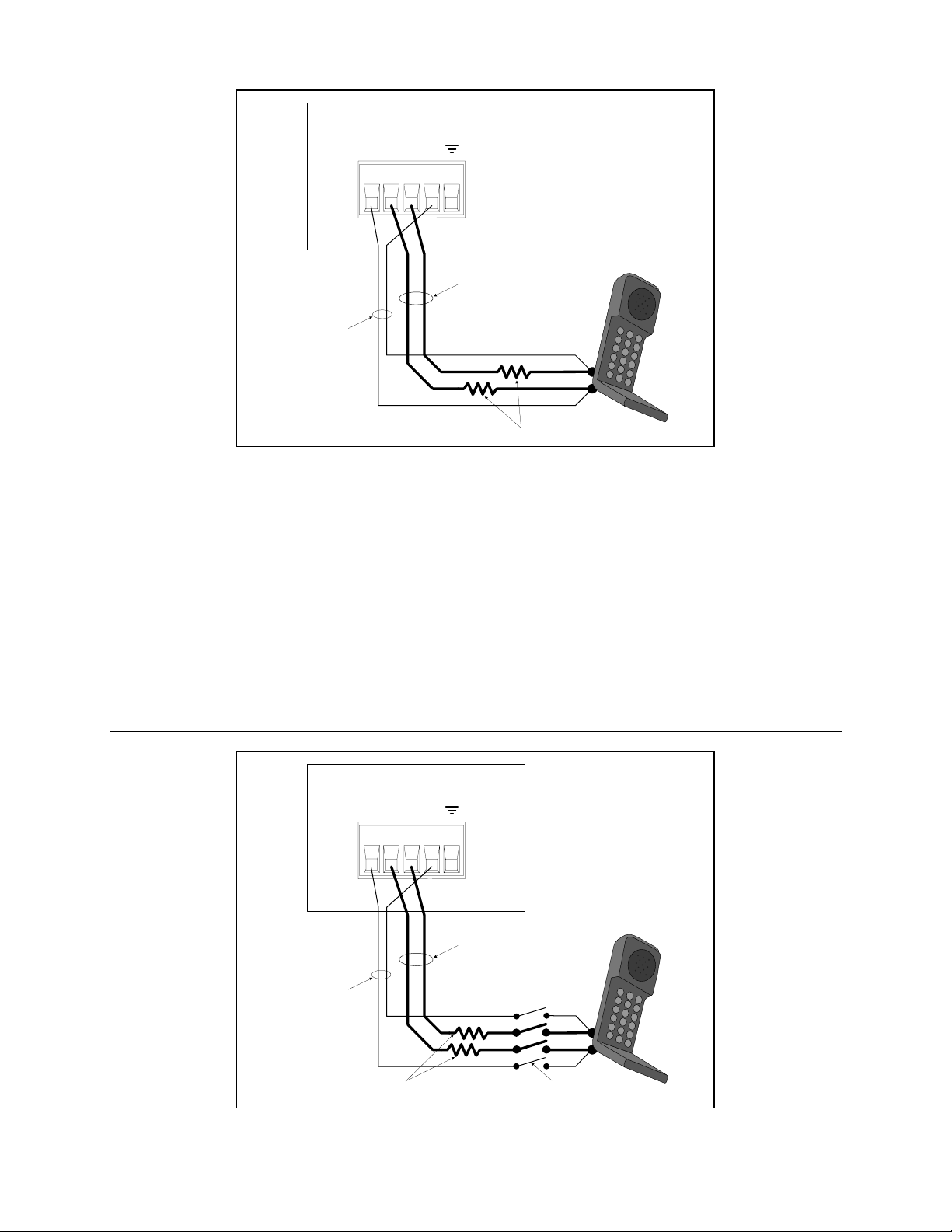
Figure 3-3 shows how to connect remote sense leads and load leads when external disconnect relays are
included in the load path.
NOTE: In this arrangement, the output of the unit should be programmed OFF before the relays
are switched. This is because if the load leads are opened before the sense leads, the
overvoltage protection circuit will trip if it is enabled.
OUTPUT 1/OUTPUT 2
CONNECTOR
-S - + +S
TWIST LEADS
TWIST PAIR
+
LOAD
WIRE RESISTANCE
_
DISCONNECT RELAYS
Figure 3-3. Remote Sense Connections with External Relays
30
Loading...