


SPECIAL MESSAGE SECTION
PRODUCT SAFETY MARKINGS: Yamaha electronic products may have either labels similar to the graphics shown below or molded/stamped facsimiles of these graphics on the enclosure. The explanation of these graphics appears on this page. Please observe all cautions indicated on this page and those indicated in the safety instruction section.
CAUTION |
RISK OF ELECTRIC SHOCK |
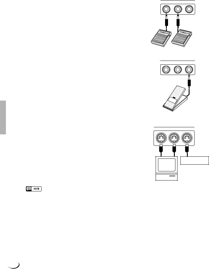
DO NOT OPEN |
CAUTION: TO REDUCE THE RISK OF ELECTRIC SHOCK. |
DO NOT REMOVE COVER (OR BACK). |
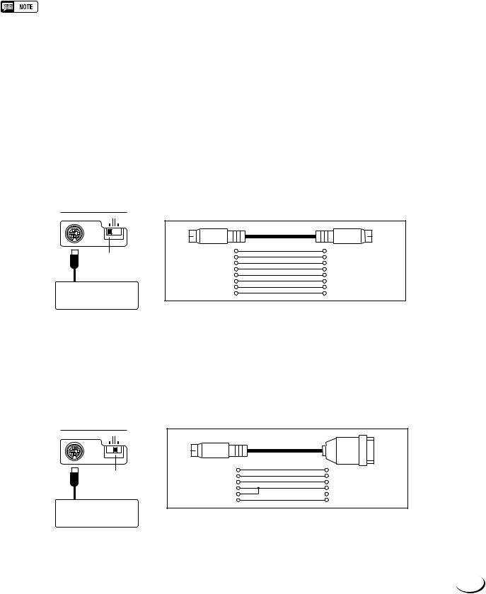
NO USER-SERVICEABLE PARTS INSIDE. |
REFER SERVICING TO QUALIFIED SERVICE PERSONNEL. |
The exclamation point within the equilateral triangle is intended to alert the user to the presence of important operating and maintenance (servicing) instructions in the literature accompanying the product.
The lightning flash with arrowhead symbol, within the equilateral triangle, is intended to alert the user to the presence of uninsulated “dangerous voltage” within the product’s enclosure that may be of sufficient magnitude to constitute a risk of electrical shock.
IMPORTANT NOTICE: All Yamaha electronic products are tested and approved by an independent safety testing laboratory in order that you may be sure that when it is properly installed and used in its normal and customary manner, all foreseeable risks have been eliminated. DO NOT modify this unit or commission others to do so unless specifically authorized by Yamaha. Product performance and/or safety standards may be diminished. Claims filed under the expressed warranty may be denied if the unit is/has been modified. Implied warranties may also be affected.
SPECIFICATIONS SUBJECT TO CHANGE: The information contained in this manual is believed to be correct at the time of printing. However, Yamaha reserves the right to change or modify any of the specifications without notice or obligation to update existing units.
ENVIRONMENTAL ISSUES: Yamaha strives to produce products that are both user safe and environmentally friendly. We sincerely believe that our products and the production methods used to produce them, meet these goals. In keeping with both the letter and the spirit of the law, we want you to be aware of the following:
Battery Notice: This product MAY contain a small nonrechargable battery which (if applicable) is soldered in place. The average life span of this type of battery is approximately five years. When replacement becomes necessary, contact a qualified service representative to perform the replacement.
Warning: Do not attempt to recharge, disassemble, or incinerate this type of battery. Keep all batteries away from children. Dispose of used batteries promptly and as regulated by applicable laws. Note: In some areas, the servicer is required by law to return the defective parts. However, you do have the option of having the servicer dispose of these parts for you.
Disposal Notice: Should this product become damaged beyond repair, or for some reason its useful life is considered to be at an end, please observe all local, state, and federal regulations that relate to the disposal of products that contain lead, batteries, plastics, etc.
NOTICE: Service charges incurred due to lack of knowledge relating to how a function or effect works (when the unit is operating as designed) are not covered by the manufacturer’s warranty, and are therefore the owners responsibility. Please study this manual carefully and consult your dealer before requesting service.
NAME PLATE LOCATION: The graphic below indicates the location of the name plate. The model number, serial number, power requirements, etc., are located on this plate. You should record the model number, serial number, and the date of purchase in the spaces provided below and retain this manual as a permanent record of your purchase.
CAUTION
Model _____________________________________
Serial No. __________________________________
Purchase Date ______________________________
92-469-

IMPORTANT SAFETY INSTRUCTIONS
INFORMATION RELATING TO PERSONAL INJURY, ELECTRICAL SHOCK, AND FIRE HAZARD POSSIBILITIES HAS BEEN INCLUDED IN THIS LIST.
WARNING- When using any electrical or electronic product, basic precautions should always be followed. These precautions include, but are not limited to, the following:
1. Read all Safety Instructions, Installation Instructions, Special Message Section items, and any Assembly Instructions found in this manual BEFORE making any connections, including connection to the main supply.
2. Main Power Supply Verification: Yamaha products are manufactured specifically for the supply voltage in the area where they are to be sold. If you should move, or if any doubt exists about the supply voltage in your area, please contact your dealer for supply voltage verification and (if applicable) instructions. The required supply voltage is printed on the name plate. For name plate location, please refer to the graphic found in the Special Message Section of this manual.
3. This product may be equipped with a polarized plug (one blade wider than the other). If you are unable to insert the plug into the outlet, turn the plug over and try again. If the problem persists, contact an electrician to have the obsolete outlet replaced. Do NOT defeat the safety purpose of the plug.
4. Some electronic products utilize external power supplies or adapters. Do NOT connect this type of product to any power supply or adapter other than one described in the owners manual, on the name plate, or specifically recommended by Yamaha.
5. WARNING: Do not place this product or any other objects on the power cord or place it in a position where anyone could walk on, trip over, or roll anything over power or connecting cords of any kind. The use of an extension cord is not recommended! If you must use an extension cord, the minimum wire size for a 25' cord (or less) is 18 AWG. NOTE: The smaller the AWG number, the larger the current handling capacity. For longer extension cords, consult a local electrician.
6. Ventilation: Electronic products, unless specifically designed for enclosed installations, should be placed in locations that do not interfere with proper ventilation. If instructions for enclosed installations are not provided, it must be assumed that unobstructed ventilation is required.
7. Temperature considerations: Electronic products should be installed in locations that do not significantly contribute to their operating temperature. Placement of this product close to heat sources such as; radiators, heat registers and other devices that produce heat should be avoided.
8. This product was NOT designed for use in wet/damp locations and should not be used near water or exposed to rain. Examples of wet/damp locations are; near a swimming pool, spa, tub, sink, or wet basement.
9. This product should be used only with the components supplied or; a cart, rack, or stand that is recommended by the manufacturer. If a cart, rack, or stand is used, please observe all safety markings and instructions that accompany the accessory product.
10. The power supply cord (plug) should be disconnected from the outlet when electronic products are to be left unused for extended periods of time. Cords should also be disconnected when there is a high probability of lightening and/or electrical storm activity.
11. Care should be taken that objects do not fall and liquids are not spilled into the enclosure through any openings that may exist.
12. Electrical/electronic products should be serviced by a qualified service person when:
a.The power supply cord has been damaged; or
b.Objects have fallen, been inserted, or liquids have been spilled into the enclosure through openings; or
c.The product has been exposed to rain: or
d.The product dose not operate, exhibits a marked change in performance; or
e.The product has been dropped, or the enclosure of the product has been damaged.
13.Do not attempt to service this product beyond that described in the user-maintenance instructions. All other servicing should be referred to qualified service personnel.
14.This product, either alone or in combination with an amplifier and headphones or speaker/s, may be capable of producing sound levels that could cause permanent hearing loss. DO NOT operate for a long period of time at a high volume level or at a level that is uncomfortable. If you experience any hearing loss or ringing in the ears, you should consult an audiologist. IMPORTANT: The louder the sound, the shorter the time period before damage occurs.
15.Some Yamaha products may have benches and/or accessory mounting fixtures that are either supplied as a part of the product or as optional accessories. Some of these items are designed to be dealer assembled or installed. Please make sure that benches are stable and any optional fixtures (where applicable) are well secured BEFORE using. Benches supplied by Yamaha are designed for seating only. No other uses are recommended.
PLEASE KEEP THIS MANUAL
92-469-2
PRECAUTIONS
PLEASE READ CAREFULLY BEFORE PROCEEDING
* Please keep these precautions in a safe place for future reference.
 WARNING
Always follow the basic precautions listed below to avoid the possibility of serious injury or even death from electrical shock, short-circuiting, damages, fire or other hazards. These precautions include, but are not limited to, the following:
•Do not open the instrument or attempt to disassemble the internal parts or modify them in any way. The instrument contains no user-serviceable parts. If it should appear to be malfunctioning, discontinue use immediately and have it inspected by qualified Yamaha service personnel.
•Do not expose the instrument to rain, use it near water or in damp or wet conditions, or place containers on it containing liquids which might spill into any openings.
•If the power cord or plug becomes frayed or damaged, or if there is a sudden loss of sound during use of the instrument, or if any unusual smells
or smoke should appear to be caused by it, immediately turn off the power switch, disconnect the electric plug from the outlet, and have the instrument inspected by qualified Yamaha service personnel.
•Only use the voltage specified as correct for the instrument. The required voltage is printed on the name plate of the instrument.
•Before cleaning the instrument, always remove the electric plug from the outlet. Never insert or remove an electric plug with wet hands.
•Check the electric plug periodically and remove any dirt or dust which may have accumulated on it.
 CAUTION
Always follow the basic precautions listed below to avoid the possibility of physical injury to you or others, or damage to the instrument or other property. These precautions include, but are not limited to, the following:
•Do not place the power cord near heat sources such as heaters or radiators, and do not excessively bend or otherwise damage the cord, place heavy objects on it, or place it in a position where anyone could walk on, trip over, or roll anything over it.
•When removing the electric plug from the instrument or an outlet, always hold the plug itself and not the cord. Pulling by the cord can damage it.
•Do not connect the instrument to an electrical outlet using a multipleconnector. Doing so can result in lower sound quality, or possibly cause overheating in the outlet.
•Remove the electric plug from the outlet when the instrument is not to be used for a long time, or during electrical storms.
•Before connecting the instrument to other electronic components, turn off the power for all components. Before turning the power on or off for all components, set all volume levels to minimum.
•Do not expose the instrument to excessive dust or vibrations, or extreme cold or heat (such as in direct sunlight, near a heater, or in a car during the day) to prevent the possibility of panel disfiguration or damage to the internal components.
•Do not use the instrument near other electrical products such as televisions, radios, or speakers, since this might cause interference which can affect proper operation of the other products.
•Do not place the instrument in an unstable position where it might accidentally fall over.
•Before moving the instrument, remove all connected cables.
•When cleaning the instrument, use a soft, dry cloth. Do not use paint thinners, solvents, cleaning fluids, or chemical-impregnated wiping cloths. Also, do not place vinyl or plastic objects on the instrument, since this might discolor the panel or keyboard.
•Do not rest your weight on, or place heavy objects on the instrument, and do not use excessive force on the buttons, switches or connectors.
•Use only the stand specified for the instrument. When attaching the stand or rack, use the provided screws only. Failure to do so could cause damage to the internal components or result in the instrument falling over.
•Do not place objects in front of the instrument’s air vents on the top and rear panels, since this may prevent adequate ventilation of the internal components, and possibly result in the instrument overheating.
Also, be careful to place the instrument on a flat, level surface to prevent blockage of the air vents on the bottom panel.
•Do not operate the instrument for a long period of time at a high or uncomfortable volume level, since this can cause permanent hearing loss. If you experience any hearing loss or ringing in the ears, consult a physician.
■REPLACING THE BACKUP BATTERY
The PSR-8000 requires four 1.5 V C size (LR14) batteries for memory backup power. If no backup batteries are installed, the memory contents will be lost when the instrument is unplugged from the AC mains supply. Please use
alkaline batteries.
1.Before changing the battery be sure to save any important data to disk by using the SAVE TO DISK function described on page 141.
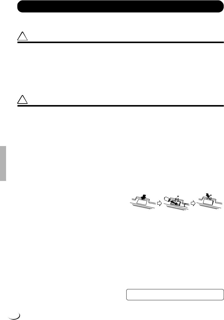
2.Turn the PSR-8000 power OFF and unplug the power cord from both the AC wall socket and the instrument’s rear panel. Turn the instrument upside down and rest it on a blanket or other soft surface.
3.Open Battery Compartment Cover
Open the battery compartment cover — located on the instrument’s bottom panel — by pressing on the two latches on the cover and pulling outward, as shown in the illustration.
4.Remove the old batteries (if installed).
Remove the old batteries and wait at least one minute to ensure that all data is fully cleared.
5.Insert Batteries
Insert the four batteries, being careful to follow the polarity markings on the bottom panel.
6.Replace Cover
Replace the compartment cover, making sure that it locks firmly in place.
•Always make sure all batteries are inserted in conformity with the +/– polarity markings. Failure to do so might result in overheating, fire, or battery fluid leakage.
•Always replace all batteries at the same time. Do not use new batteries together with old ones. Also, do not mix battery types, such as alkaline batteries with manganese batteries, or batteries from different makers, or different types of batteries from the same maker, since this can cause overheating, fire, or battery fluid leakage.
•Do not dispose of batteries in fire.
•Do not attempt to recharge batteries that are not intended to be charged.
•If the instrument is not to be in use for a long time, remove the batteries from it (after saving any important data to disk), in order to prevent possible fluid leakage from the battery.
•Keep batteries away from children.
■SAVING USER DATA
•Always save data to a floppy disk frequently, in order to help prevent the loss of important data due to a malfunction or user operating error.
Yamaha cannot be held responsible for damage caused by improper use or modifications to the instrument, or data that is lost or destroyed.
Always turn the power off when the instrument is not in use.
Make sure to discard used batteries according to local regulations.
4 (1)
Handling the Floppy Disk Drive(FDD) and Floppy Disk
Precautions
•Be sure to handle floppy disks and treat the disk drive with care. Follow the important precautions below.
Compatible Disk Type
• 3.5” 2DD and 2HD type floppy disks can be used.
■ Inserting/Ejecting Floppy Disks
DISK IN USE
To insert a floppy disk into the disk drive:
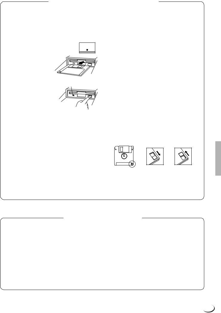
•Hold the disk so that the label of the disk is facing upward and the sliding shutter is facing forward, towards the disk slot. Carefully insert the disk into the slot, slowly pushing it all the way in until it clicks into place and the eject button pops out.
To eject a floppy disk:
This lamp is always on while the power is on.
• Before ejecting a floppy disk make
sure that the floppy disk drive is not in operation (the DISK IN USE indi-
cator should be off, except when the internal hard disk is being accessed).
Press the eject button slowly as far as it will go; the disk will automatically pop out. When the disk is fully ejected, carefully remove it by hand.
•Never attempt to remove the disk or turn the power off during recording, reading and playing back. Doing so can damage the disk and possibly the disk drive.
•If the eject button is pressed too quickly, or if it is not pressed in as far as it will go, the disk may not eject properly. The eject button may become stuck in a half-pressed position with the disk extending from the drive slot by only a few millimeters. If this happens, do not attempt to pull out the partially ejected disk, since using force in this situation can damage the disk drive mechanism or the floppy disk. To remove a partially ejected disk, try pressing the eject button once again, or push the disk back into the slot and then repeat the eject procedure.
•Be sure to remove the floppy disk from the disk drive before turning off the power. A floppy disk left in the drive for extended periods can easily pick up dust and dirt that can cause data read and write errors.
Cleaning the Disk Drive Read/Write Head
•Clean the read/write head regularly. This instrument employs a precision magnetic read/write head which, after an extended period of use,
will pick up a layer of magnetic particles from the disks used that will eventually cause read and write errors.
•To maintain the disk drive in optimum working order Yamaha recommends that you use a commercially-available dry-type head cleaning disk to clean the head about once a month. Ask your Yamaha dealer about the availability of proper head-cleaning disks.
Never insert anything but floppy disks into the disk drive. Other objects may cause damage to the disk drive or floppy disks.
■ About the Floppy Disks
To handle floppy disks with care:
•Do not place heavy objects on a disk or bend or apply pressure to the disk in any way. Always keep floppy disks in their protective cases when they are not in use.
•Do not expose the disk to direct sunlight, extremely high or low temperatures, or excessive humidity, dust or liquids.
•Do not open the sliding shutter and touch the exposed surface of the floppy disk inside.
•Do not expose the disk to magnetic fields, such as those produced by televisions, speakers, motors, etc., since magnetic fields can partially or completely erase data on the disk, rendering it unreadable.
•Never use a floppy disk with a deformed shutter or housing.
•Do not attach anything other than the provided labels to a floppy disk. Also make sure that labels are attached in the proper location.
To protect your data (Write-protect Tab):
•To prevent accidental erasure of important data, slide the disk’s writeprotect tab to the “protect” position (tab open).
Write protected |
Write enabled |
Data backup
•For maximum data security Yamaha recommends that you keep two copies of important data on separate floppy disks. This gives you a backup if one disk is lost or damaged. To make a backup disk use the COPY FILE/FD function on page 143.
YAMAHA is not responsible for damage caused by improper handling or operation.
YAMAHA provides no guarantee against disk damage.
Handling and Installation of Options
 WARNING
•Before beginning installation, switch off the power to the PSR-8000 and connected peripherals, and unplug them from the power outlet. Then remove all cables connecting the PSR-8000 to other devices. (Leaving the power cord connected while working can result in electric shock. Leaving other cables connected can interfere with work.)
•Do not disassemble, modify, or apply excessive force to board areas and connectors on hard disk, and SIMMs. Bending or tampering with boards and connectors may lead to electric shock, fire, or equipment failures.
 CAUTION
•Before handling the internal hard disk or SIMMs, you should briefly touch the metal surface to which the hard-disk or SIMM cover is attached (or
other such metallic area — be careful of any sharp edges) with your bare hand so as to drain off any static charge from your body. Note that even a slight amount of electrostatic discharge may cause damage to these components.
•It is recommended that you wear gloves to protect your hands from metallic projections on the PSR-8000 hard disk, SMMs, and other components. Touching leads or connectors with bare hands may cause finger cuts, and may also result in poor electrical contact or electrostatic damage.
•Take care to avoid dropping screws into the PSR-8000 unit. If a screw does fall in, be sure to remove it before replacing the cover and powering up the unit. Starting the unit with a loose screw inside may lead to improper operation or equipment failure. (If you are unable to retrieve a dropped screw, consult your Yamaha dealer for advice.)
*If SIMM memory, or hard disk fails to work properly, consult the item’s dealer or manufacturer for advice.
*Yamaha will not be held responsible for any damage or injury resuting from improper installation.
5
Congratulations!
You are the proud owner of an extraordinary electronic keyboard. The Yamaha PSR-8000
PortaTone combines the most advanced tone generation technology with state-of-the-art digital electronics and features to give you stunning sound quality with maximum musical versatility. The advanced Auto Accompaniment, Vocal Harmony, and Sampler features, in particular, are brilliant examples of how Yamaha technology can significantly expand your musical horizons. A large-size graphic display and easy-to-use interface also greatly enhance the operability of this advanced instrument.
In order to make the most of your PortaTone’s features and vast performance potential, we urge you to read the manuals thoroughly while trying out the various features described. Keep the manuals in a safe place for later reference.
Packing List
Your PSR-8000 includes the following items:
•PSR-8000 PortaTone x 1
•AC Power Cord x 1
•AC Plug Adaptor x 1 (in applicable areas only)
•Music Stand x 1
•Audio CD x 1 (includes sound sources for sampling: page 88)
•Floppy Disk x 1 (includes accompaniment style files: page 28)
•Owner’s Manual
•The illustrations and LCD screens as shown in this owner’s manual are for instructional purposes only, and may appear somewhat different from those on your instrument.
•Unauthorized copying of copyrighted software for purposes other than the purchaser’s personal use is prohibited.
•The Vocal Harmony feature included in this product is manufactured under license from IVL Technologies Ltd., U.S. Patent numbers 5231671, 5301259, and 5428708.
● Trademarks:
•Apple and Macintosh are trademarks of Apple Computer, Inc.
•IBM-PC/AT is a trademark of International Business MachinesCorporation.
•Windows is the registered trademark of Microsoft® Corporation.
•All other trademarks are the property of their respective holders.
The Panel Logos
The logos printed on the PSR-8000 panel indicate standards/formats it supports and special features it includes.
GM System Level 1
“GM System Level 1” is an addition to the MIDI standard which guarantees that any data conforming to the standard will play accurately on any GM-compatible tone generator or synthesizer from any manufacturer.
XG
XG is a new Yamaha MIDI specification which significantly expands and improves on the “GM System Level 1” standard with greater voice handling capacity, expressive control, and effect capability while retaining full compatibility with GM. By using the PSR-8000’s XG voices, it is possible to record XGcompatible song files.
XF
The Yamaha XF format enhances the SMF (Standard MIDI File) strandard with greater functionality and open-ended expandability for the future. The PSR-8000 is capable of displaying lyrics when an XF file containing lyric data is played.
•SMF (Standard MIDI File) is the most common format used for MIDI sequence files. The PSR-8000 is compatible with SMF Formats 0 and 1, and records “song” data using SMF Format 0.
6
¢¢¢¢¢¢¢¢¢¢¢¢¢¢¢¢QQQQQQQQQQQQQQQQ,,,,,,,,,,,,,,,,
¢¢¢¢¢¢¢¢¢¢¢¢¢¢¢¢¢QQQQQQQQQQQQQQQQQ,,,,,,,,,,,,,,,,,
Main Features
¢¢¢¢¢¢¢¢¢¢¢¢¢¢¢¢¢QQQQQQQQQQQQQQQQQ,,,,,,,,,,,,,,,,,
The PSR-8000 is a sophisticated electronic keyboard which offers a comprehensive range of features for extensive musical versatility and expressive control: a touch-sensitive 61-key keyboard, an outstanding range of voices (including XG voices), top quality auto-accompani- ment with an extensive range of styles, song recording and playback capability, registration memory, and a built-in floppy disk for convenient data storage and retrieval, and more.
The following features, in particular, give the PSR-8000 extraordinary musical production and performance power.
●High-quality sampling capability — with expandable wave memory — lets you sample and edit sounds via microphone or from line sources, and then use the sampled waveforms in original voices.
●Unique Vocal Harmony feature incorporates advanced voice-processing technology to automatically produce vocal harmony based on a lead vocal, making a single singer sound like a vocal group.
●An advanced effect system incorporating 8 separate DSPs (Digital Signal Processors) and 5-band master equalization adds depth, ambience, and animation to your sound.
●Comprehensive Mixing Console displays provide professional sound control and production capability.
●Large multi-function LCD display panel with displaybased buttons and dials, plus comprehensive display prompts and messages, makes operation easy and intuitive.
●Create original voices using the Voice Creator feature for a totally original sound.
●Style Creator feature lets you create “groove style” variations on existing styles, or create entirely new styles that are a perfect match for your performing requirements.
●One Touch Setting feature automatically selects appropriate voice, effect, and other settings for the selected accompaniment style — all you have to do is select a style, press the ONE TOUCH SETTING button and play.
●Multi Pads record and play short rhythmic and melodic sequences that can be used to add impact and variety to your performances.
●Voice/Style List Customize feature lets you rearrange the list contents for fast, efficient access in performance situations.
●Unique “Talk” function instantly makes the settings you need for mid-performance announcements and interludes.
●Loop Send and Return jacks allow extra system flexibility: connect external signal-processing equipment for enhanced effect capability, or feed a mixer for improved sound and on-stage monitoring quality.
●Optional internal hard disk provides high-volume, high-speed data storage and retrieval.
●A selection of MIDI Templates eliminates tedious setup procedures by providing instantly selectable MIDI setups for a range of situations.
●To Host interface plus a range of MIDI functions for expanded musical performance (General MIDI System Level 1 and Yamaha XG/XF compatible).
DOC
The DOC voice allocation format provides data playback compatibility with a wide range of Yamaha instruments and MIDI devices, including the Clavinova series.
Style File Format
The Style File Format — SFF — is Yamaha’s original style file format which uses a unique conversion system to provide high-quality automatic accompaniment based on a wide range of chord types. The PSR-8000 uses the SFF internally, reads optional SFF style disks, and creates SFF styles using the STYLE CREATOR feature.
Vocal Harmony
Vocal Harmony employs state-of-the-art digital signal processing technology to automatically add appropriate vocal harmony to a lead vocal line sung by the user. Vocal Harmony can even change the character and gender of the lead voice as well as the added voices to produce a wide range of vocal harmony effects.
7

¢¢¢¢¢¢¢¢¢¢¢¢¢¢¢¢¢QQQQQQQQQQQQQQQQQ,,,,,,,,,,,,,,,,,
¢Q,,¢¢¢¢¢¢¢¢¢¢¢¢¢¢¢¢QQQQQQQQQQQQQQQQ,,,,,,,,,,,,,,,,
Contents
¢¢¢¢¢¢¢¢¢¢¢¢¢¢¢¢¢¢QQQQQQQQQQQQQQQQQQ,,,,,,,,,,,,,,,,,,
Panel Controls |
10 |
Connections & Music Stand |
12 |
The Demonstration |
17 |
The PSR-8000 Display & |
|
Display-based Controls |
19 |
■ The MIXING CONSOLE Buttons .... |
19 |
■ The [EXIT] Button ............................ |
20 |
■ The [DIRECT ACCESS] Button ...... |
20 |
■ The [LCD CONTRAST] Control ...... |
20 |
■ The 5-language Help Function ........ |
20 |
■ Display Messages ........................... |
21 |
■ Name Entry ..................................... |
21 |
Playing the PSR-8000 |
22 |
■ Before You Begin ............................ |
22 |
The PSR-8000 Parts & Voices ......... |
22 |
■ Part Poly/Mono Modes & Mono |
|
Note Priority .................................... |
22 |
■ The XG Voices ................................ |
23 |
■ The Organ Flute Voice .................... |
23 |
■ Keyboard Percussion and Special |
|
Effects ............................................. |
24 |
Procedure: Part Selection and Voice |
|
Assignment .......................................... |
24 |
Voice Effects ........................................ |
26 |
Other Play Mode Functions ............. |
26 |
■ Master Transpose ........................... |
26 |
■ Octave Change ............................... |
27 |
■ Left Hold .......................................... |
27 |
■ Pitch Bend & Modulation Wheels .... |
27 |
Using the Accompaniment |
|
Section |
28 |
Procedure: Auto Accompaniment ......... |
28 |
■ Auto Accompaniment Fingering |
|
Modes ............................................. |
30 |
■Auto Accompaniment Start Modes .. 33
■The MAIN A and MAIN B Sections
and Fill-ins ....................................... |
34 |
■ Tempo Control ................................ |
35 |
■ Fade-ins and Fade-outs .................. |
35 |
■ Synchronized Stop .......................... |
35 |
■ Accompaniment Volume ................. |
36 |
■ Accompaniment Part Switching ...... |
36 |
■ Virtual Arranger ............................... |
36 |
■ Harmony/Echo ................................ |
37 |
■ One Touch Setting .......................... |
38 |
The Mixing Console |
39 |
Mixing Console Parameters ............ |
39 |
VOLUME/PAN/EQ .............................. |
40 |
■ VOLUME ......................................... |
40 |
■ PANPOT ......................................... |
40 |
■ EQ LOW .......................................... |
40 |
■ EQ HIGH ......................................... |
40 |
■ HPF1 ............................................... |
40 |
■ HPF2 ............................................... |
40 |
FILTER ............................................... |
41 |
■ HARMONIC CONTENT .................. |
41 |
■ BRIGHTNESS ................................. |
41 |
EFFECT DEPTH ................................. |
41 |
■ REVERB (DSP1) ............................. |
41 |
■ CHORUS (DSP2) ............................ |
41 |
■ DSP3 ............................................... |
42 |
■ DSP4-7 ............................................ |
42 |
EFFECT TYPE .................................... |
42 |
■ Type Page ....................................... |
42 |
● EFFECT BLOCK & TYPE ........... |
42 |
● TYPE LIST .................................. |
42 |
■ Parameter Page .............................. |
42 |
● BLOCK ........................................ |
42 |
● TYPE ........................................... |
42 |
● PARAMETER .............................. |
43 |
● VALUE ........................................ |
43 |
● LEVEL ......................................... |
43 |
● USER SET .................................. |
43 |
TUNING .............................................. |
44 |
■ TRANSPOSE .................................. |
44 |
■ TUNING .......................................... |
44 |
■ OCTAVE ......................................... |
44 |
■ PITCH BEND RANGE ..................... |
44 |
■ PORTAMENTO TIME ..................... |
44 |
MASTER EQ ....................................... |
45 |
■ EQ1 … EQ5 .................................... |
45 |
■ Q & FREQ ....................................... |
45 |
■ TOTAL GAIN ADJUST .................... |
45 |
■ STORE ............................................ |
45 |
Registration Memory |
46 |
Registering the Panel Settings ....... |
46 |
Recalling the Registered Panel |
|
Settings ................................................. |
47 |
The Freeze Function .......................... |
47 |
Organ Flute Voice Editing |
48 |
■ ORGAN TYPE ................................. |
48 |
■ ROTARY SP SPEED ...................... |
48 |
■ VIBRATO ON/OFF .......................... |
48 |
■ VIBRATO DEPTH ........................... |
48 |
■ FOOTAGE ....................................... |
48 |
■ VOLUME & ATTACK ...................... |
49 |
■ EFFECT & EQ SETTINGS .............. |
49 |
Custom Voice Creator |
51 |
Procedure: Engaging the Easy/ |
|
Full Edit Mode ..................................... |
51 |
The Easy Edit Parameters ............... |
52 |
EDIT .................................................... |
52 |
■ FILTER ............................................ |
52 |
■ EG ................................................... |
52 |
■ VIBRATO ........................................ |
53 |
■ VOLUME ......................................... |
53 |
STORE/CLEAR .................................. |
53 |
■ NAME .............................................. |
53 |
■ STORE ............................................ |
53 |
■ CLEAR CUSTOM VOICE ............... |
54 |
The Full Edit Parameters .................. |
54 |
■ ELEMENT SELECTION |
|
(not available for the Drum Kits) .................. |
54 |
VOICE ................................................. |
55 |
■ MASTER VOLUME ......................... |
55 |
■ INITIAL TOUCH CURVE ................. |
55 |
■ SCALE CURVE ............................... |
55 |
■ MODULATION ................................ |
55 |
■ AFTER TOUCH ............................... |
55 |
E1:WAVEFORM ................................. |
56 |
■ WAVEFORM |
|
(INSTRUMENT for the Drum Kits) ................ |
56 |
■ COARSE TUNE/FINE TUNE .......... |
56 |
■ VOLUME ......................................... |
56 |
■ KEY ON DELAY .............................. |
56 |
■ PAN ................................................. |
56 |
■ NOTE LIMIT |
|
(not available for the Drum Kits) .................. |
56 |
■ VELOCITY LIMIT |
|
(not available for the Drum Kits) .................. |
56 |
E2:EG ................................................. |
57 |
■ AMP RATE |
|
(Amplitude Envelope Rate) ............. |
57 |
■ AMP LEVEL |
|
(Amplitude Envelope Level) ............ |
57 |
■ PITCH RATE (Pitch Envelope Rate) 58 |
|
■ PITCH LEVEL ................................. |
58 |
■ FILTER RATE ................................. |
58 |
■ FILTER LEVEL ................................ |
58 |
E3:FILTER .......................................... |
59 |
■ FILTER1 & FILTER2 ....................... |
59 |
■ RESONANCE ................................. |
59 |
■ TOUCH TO FILTER ........................ |
59 |
E4:LFO ............................................... |
59 |
■ LFO (Low Frequency Oscillator) ..... |
59 |
■ DELAY (Delay Vibrato) ................... |
60 |
VOICE SET ......................................... |
60 |
■ REVERB, CHORUS, and DSP |
|
DEPTH ............................................ |
60 |
■ DSP TYPE and VARIATION ........... |
60 |
■ EQ LOW and HIGH ......................... |
60 |
STORE/CLEAR .................................. |
61 |
■ NAME .............................................. |
61 |
■ STORE ............................................ |
61 |
■ CLEAR CUSTOM VOICE ............... |
61 |
The Custom Style Creator |
62 |
Procedure: Custom Style Recording .... |
62 |
CUSTOM STYLE CREATOR Param- |
|
eters ....................................................... |
66 |
■ Exiting ............................................. |
66 |
BASIC ................................................. |
66 |
■ SECTION/PATTERN LENGTH/ |
|
BEAT/TEMPO ................................. |
66 |
■ PART COPY ................................... |
67 |
SETUP ................................................ |
67 |
■ VOICE ............................................. |
67 |
■ SETUP COPY ................................. |
68 |
EDIT .................................................... |
68 |
■ QUANTIZE ...................................... |
68 |
■ VELOCITY CHANGE ...................... |
69 |
■ MEASURE COPY ........................... |
69 |
■ MEASURE CLEAR ......................... |
69 |
■ REMOVE CONTROL EVENT ......... |
69 |
■ REMOVE DUPLICATE NOTES ...... |
70 |
STORE/CLEAR .................................. |
70 |
■ NAME .............................................. |
70 |
■ STORE ............................................ |
70 |
■ CLEAR CUSTOM STYLE ............... |
70 |
PARAMETER EDIT ............................ |
71 |
■ PART/SOURCE ROOT/SOURCE |
|
CHORD ........................................... |
71 |
■ NTR/NTT ......................................... |
71 |
■ HIGH KEY/NOTE LIMIT .................. |
72 |
■ RTR ................................................. |
72 |
8

,,,,,,,,,,,,,,,,,QQQQQQQQQQQQQQQQQ¢¢¢¢¢¢¢¢¢¢¢¢¢¢¢¢¢
,,,,,,,,,,,,,,,,,QQQQQQQQQQQQQQQQQ¢¢¢¢¢¢¢¢¢¢¢¢¢¢¢¢¢Contents
Custom Style Recording via an |
|
External Sequence Recorder .......... |
73 |
■ Connections .................................... |
73 |
■ Creating the Data ............................ |
73 |
■ Saving and Loading the Sequence |
|
Data ................................................. |
75 |
■ Refining the Style ............................ |
75 |
The Groove Style Creator |
76 |
Procedure: Creating a Groove Style ..... |
76 |
GROOVE STYLE CREATOR |
|
Parameters ........................................... |
77 |
■ Exiting ............................................. |
77 |
SETUP ................................................ |
78 |
■ PART ON/OFF/TEMPO .................. |
78 |
■ VOICE ............................................. |
78 |
■ SETUP COPY ................................. |
78 |
GROOVE ............................................ |
79 |
■ GROOVE ........................................ |
79 |
■ SETUP COPY ................................. |
79 |
DYNAMICS ......................................... |
80 |
■ DYNAMICS ..................................... |
80 |
■ SETUP COPY ................................. |
80 |
STORE/CLEAR .................................. |
80 |
■ NAME .............................................. |
80 |
■ STORE ............................................ |
81 |
■ GROOVE STYLE CLEAR ............... |
81 |
■ STORE AS CUSTOM STYLE ......... |
81 |
■ CUSTOM STYLE CLEAR ............... |
81 |
DRUM EXCHANGE ............................ |
82 |
■ DRUM EXCHANGE ........................ |
82 |
■ SETUP COPY ................................. |
82 |
Vocal Harmony |
83 |
Using Vocal Harmony ....................... |
83 |
■ Setting Up ....................................... |
83 |
■ The VOCAL/SAMPLING Buttons .... |
83 |
■ Selecting a VOCAL HARMONY |
|
Type ................................................ |
84 |
■ Producing the VOCAL HARMONY |
|
Effect ............................................... |
84 |
Editing the Vocal Harmony |
|
Parameters ........................................ |
84 |
■ The Vocal Harmony Modes ............. |
85 |
Sampling |
88 |
PSR-8000 Waves & Waveforms ....... |
88 |
Setting Up for Sampling ................... |
89 |
■ Connecting the Source .................... |
89 |
■ Setting Levels .................................. |
89 |
Sampling & File Import ..................... |
90 |
■ Sampling New Material ................... |
90 |
■ NAME/CLEAR ................................. |
92 |
Wave Edit ........................................... |
93 |
■ EDIT ................................................ |
93 |
■ NAME/CLEAR/DISK ....................... |
96 |
Waveform Edit ................................... |
97 |
■ EDIT ................................................ |
97 |
■ NAME/CLEAR/DISK ....................... |
98 |
■ STORE AS CUSTOM VOICE ......... |
99 |
Song Playback |
100 |
Procedure: Song Playback .................... |
100 |
Enter Next Song .............................. |
101 |
Pause, Fast Forward & Reverse .... |
102 |
Lyric Display .................................... |
102 |
The CHORD DETECT and VOCAL |
|
HARM. Parameters .......................... |
102 |
■ CHORD DETECT .......................... |
102 |
■ VOCAL HARM. ............................. |
102 |
Setting the Song Playback Order .. |
103 |
MIXING CONSOLE Operation During |
|
Song Playback ................................ |
103 |
■ FADER .......................................... |
103 |
■ FULL ............................................. |
104 |
Song Recording |
105 |
Procedure: Song Recording ................. |
105 |
Procedure: Quick Record ...................... |
106 |
■ THE TRACK INDICATORS ........... |
108 |
■ TRACK DELETE ........................... |
108 |
■ PLAYBACK ................................... |
108 |
■ EXITING ........................................ |
108 |
Procedure: Chord Step Recording ...... |
109 |
■ DELETING EVENTS ..................... |
110 |
■ INSERTING OR DELETING |
|
MEASURES .................................. |
110 |
■ SAVING THE CHORD STEP |
|
DATA ............................................. |
110 |
Quick Record Mode Edit Functions111 |
|
■ RENAME SONG ........................... |
111 |
■ SONG DELETE ............................. |
111 |
Procedure: Multi Track Record ............ |
111 |
■ THE TRACK INDICATORS ........... |
113 |
■ TRACK DELETE ........................... |
114 |
■ PLAYBACK ................................... |
114 |
■ EXITING ........................................ |
114 |
Procedure: Punch-In & Replace |
|
Recording ........................................... |
114 |
Multi Track Record Mode Edit |
|
Functions ......................................... |
116 |
■ RENAME SONG ........................... |
116 |
■ QUANTIZE .................................... |
116 |
■ TRACK MIX ................................... |
117 |
■ NOTE SHIFT ................................. |
117 |
■ SONG DELETE ............................. |
117 |
Multi Track Record Set Up ............. |
118 |
■ VOICE ........................................... |
118 |
■ OTHER SET UP PARAMETERS .. |
118 |
The Multi Pads |
119 |
MULTI PAD Playback ...................... |
119 |
Procedure: MULTI PAD Recording ..... |
119 |
■ MULTI PAD NAME ........................ |
121 |
■ MULTI PAD CLEAR ...................... |
121 |
The Repeat & Chord Match Modes 121 |
|
■ REPEAT ........................................ |
121 |
■ CHORD MATCH ........................... |
121 |
The PSR-8000 “Functions” |
122 |
The FUNCTION Parameters ........... |
122 |
■ The [EXIT] Button .......................... |
122 |
F1: MASTER TUNE/SCALE ............ |
123 |
■ MASTER TUNE ............................ |
123 |
■ SCALE (ARABIC) .......................... |
123 |
F2: SPLIT POINT/FINGERING ........ |
123 |
■ SPLIT POINT ................................ |
123 |
■ FINGERING .................................. |
124 |
F3: CONTROLLER ........................... |
124 |
■ FOOT CONTROLLER ................... |
124 |
■ PANEL CONTROLLER ................. |
126 |
F4: REGISTRATION/ONE TOUCH |
|
SETTING/VOICE SET ...................... |
127 |
■ REGISTRATION ........................... |
127 |
■ ONE TOUCH SETTING ................ |
127 |
■ VOICE SET ................................... |
128 |
F5: HARMONY/ECHO ...................... |
129 |
F6: CUSTOMIZE LIST ...................... |
129 |
F7: TALK SETTING ......................... |
130 |
F8: UTILITY ...................................... |
131 |
F9: MIDI ............................................ |
132 |
■ TEMPLATE ................................... |
132 |
■ SYSTEM ....................................... |
134 |
■ TRANSMIT .................................... |
135 |
■ RECEIVE ...................................... |
136 |
■ PANEL CONTROL ........................ |
138 |
Disk Operations |
139 |
The DISK Parameters ...................... |
139 |
■ Exiting ........................................... |
140 |
LOAD FROM DISK ........................... |
140 |
SAVE TO DISK ................................. |
141 |
COPY FILE/FD ................................. |
143 |
■ Copying Files ................................ |
143 |
■ Copying Floppy Disks ................... |
144 |
CHANGE SONG ORDER ................. |
144 |
RENAME FILE/SONG ...................... |
145 |
DELETE FILE/SONG ....................... |
145 |
FORMAT FD ..................................... |
146 |
EDIT DIRECTORY ............................ |
146 |
■ NEW DIR ....................................... |
146 |
■ RENAME ....................................... |
146 |
■ DELETE ........................................ |
146 |
FORMAT HARD DISK ...................... |
147 |
CHECK HARD DISK ........................ |
147 |
Troubleshooting |
148 |
Index |
150 |
Installing Options ............................. |
152 |
Optional SIMM Installation ............. |
152 |
Optional Hard Disk Installation ...... |
156 |
Voice List ............................................ |
159 |
Keyboard Drum Assignments ...... |
166 |
Style List ............................................. |
168 |
Direct Access Chart ......................... |
170 |
Parameter Chart ................................ |
171 |
Effect Signal Flow Chart ................ |
176 |
MIDI Data Format .............................. |
177 |
MIDI Implementation Chart ............ |
196 |
Audio Sampling Library CD |
|
Contents .............................................. |
200 |
Specifications .................................... |
203 |
9
¢¢¢¢¢¢¢¢¢¢¢¢¢¢¢¢¢QQQQQQQQQQQQQQQQQ,,,,,,,,,,,,,,,,,
¢Q,,¢¢¢¢¢¢¢¢¢¢¢¢¢¢¢¢QQQQQQQQQQQQQQQQ,,,,,,,,,,,,,,,,
Panel Controls
¢¢¢¢¢¢¢¢¢¢¢¢¢¢¢¢¢¢QQQQQQQQQQQQQQQQQQ,,,,,,,,,,,,,,,,,,
|
|
|
|
|
|
|
|
|
5 |
|
|
|
6 |
|
|
# |
|
|
|
|
|
4 |
|
|
|
|
OVERALL/UTILITY |
A |
|
||||
|
|
|
|
|
|
|
|
|
|
|
||||||
|
|
|
|
|
|
|
STYLE |
|
|
VOICE |
STYLE |
FUNCTION |
|
@ |
||
|
|
|
|
|
|
|
|
|
CREATOR |
CREATOR |
|
|||||
|
|
|
|
|
|
|
|
|
|
|
||||||
|
|
|
2 |
|
SONG |
|
|
8BEAT 1 |
DANCEFLOOR |
LATIN |
|
|
|
|
B |
|
|
|
|
|
|
|
|
|
|
|
|
||||||
|
|
|
|
REW |
FF |
|
|
|
|
|
SONG/M.PAD |
|
|
|
|
|
|
|
|
|
|
|
|
|
|
|
|
|
|
|
|
||
|
|
DEMO/HELP |
|
|
|
|
8BEAT 2 |
DISCO |
BALLROOM |
|
RECORDING |
SAMPLING |
DISK |
C |
|
|
|
|
|
|
|
|
|
|
|
|
|
|
|
|
|
||
|
|
|
|
|
PAUSE |
|
|
|
SWING & |
MARCH & |
|
|
|
|
|
|
|
|
|
|
|
|
|
|
16BEAT |
|
|
|
|
|
|
||
|
|
|
|
|
|
|
|
JAZZ |
WALTZ |
|
|
|
|
|
|
|
|
|
|
|
|
|
|
|
|
|
|
|
|
D |
|
||
|
|
|
|
|
|
|
|
|
|
|
|
7 |
|
|
|
|
|
|
MASTER VOLUME |
|
|
|
BALLAD |
R & B |
GROOVE |
|
|
DIRECT ACCESS |
|
|
|||
|
|
|
|
|
|
|
|
|
|
|
|
|
||||
|
|
|
|
|
|
|
|
STYLE |
|
|
|
|
|
|||
|
|
|
|
|
|
|
|
|
|
|
|
|
|
|
|
|
|
|
|
|
|
SONG SELECT |
|
|
|
|
|
|
RESET |
|
E |
|
|
|
|
|
|
|
|
|
|
|
|
CUSTOM |
|
|
|
|
|
|
|
|
|
|
|
|
|
|
ROCK |
COUNTRY |
|
8 |
|
|
|
$ |
|
|
|
|
|
|
|
|
|
STYLE |
|
|
MASTER |
|
||||
|
|
|
|
|
|
|
|
|
|
|
|
|
||||
|
|
|
|
|
SONG |
|
|
|
AUTO |
|
|
|
TRANSPOSE |
|
||
|
|
MIN |
MAX |
|
|
|
ACCOMPANIMENT |
|
|
|
|
BEAT |
|
|
||
|
|
|
3 |
|
|
|
|
|
|
|
|
|
|
|
|
|
|
|
|
|
|
|
|
|
|
|
9 |
|
|
PART |
|
||
|
|
|
|
|
|
|
|
|
|
|
|
|
|
TEMPO |
|
|
1 |
SYNC |
SYNC |
START/ |
INTRO A/B MAIN/AUTO FILL |
ENDING A/B |
FADE |
|
|
|
|
RESET |
|
PART |
% |
||
STOP |
START |
STOP |
/rit. |
IN/OUT |
|
|
|
|
|
|
||||||
|
|
|
|
M.PAD BANK 1~60 |
STOP |
|
|
|
|
|
||||||
|
|
|
|
|
|
|
|
|
|
|
|
|
|
|||
|
|
|
|
|
A |
B |
|
|
|
|
1 |
2 |
3 |
4 |
|
|
|
STAND BY |
|
|
0ACCOMPANIMENT CONTROL |
|
|
|
|
!MULTI PAD |
|
|
|
|
|||
|
ON |
|
|
|
|
|
|
|
|
|
|
|||||
y |
u |
|
|
|
|
|
|
|
|
|
|
|
|
|
|
|
PITCH BEND |
MODULATION |
|
|
|
|
|
|
|
|
|
|
|
|
|
|
|
UP |
MAX |
|
|
|
|
|
|
|
|
|
|
|
|
|
|
|
DOWN |
MIN |
PHONES MIC/LINE IN
1 STAND BY/ON Button .............................. |
page 17 |
2 DEMO/HELP Button ......................... |
pages 17, 20 |
3 MASTER VOLUME Control ...................... |
page 17 |
4 SONG Buttons ....................................... |
page 100 |
REW, FF, PAUSE, SONG SELECT, SONG |
|
5 STYLE Buttons ................................. |
pages 28, 36 |
8BEAT1, 8BEAT2, 16BEAT, BALLAD, ROCK, DANCEFLOOR, DISCO, SWING & JAZZ, R & B, COUNTRY, LATIN, BALLROOM, MARCH & WALTZ, GROOVE STYLE, CUSTOM STYLE, AUTO ACCOMPANIMENT, VIRTUAL ARRANGER
6 OVERALL/UTILITY Buttons
....................pages 51, 62, 88, 105, 119, 122, 139
VOICE CREATOR, STYLE CREATOR, FUCTION, SONG/M.PAD RECORDING, SAMPLING, DISK
7 DIRECT ACCESS Button................ |
pages 20, 170 |
|
8 MASTER TRANSPOSE <, > Buttons .... |
page 26 |
|
9 TEMPO <, > Buttons .............................. |
|
page 35 |
0 ACCOMPANIMENT CONTROL Buttons .. |
page 33 |
|
SYNCHRO STOP, SYNCHRO START, START/ STOP, INTRO A/B, MAIN/AUTO FILL A/B, ENDING A/B/rit., FADE IN/OUT
! MULTI PAD Buttons ............................... |
page 119 |
M.PAD BANK 1~60, STOP, 1—4 |
|
@ Liquid Crystal Display (LCD) .................... |
page 19 |
# LCD (A—J) Buttons ................................. |
page 19 |
$ MIXING CONSOLE Buttons .................... |
page 19 |
FADER, FULL |
|
10
,,,,,,,,,,,,,,,,,QQQQQQQQQQQQQQQQQ¢¢¢¢¢¢¢¢¢¢¢¢¢¢¢¢¢
,,,,,,,,,,,,,,,,,QQQQQQQQQQQQQQQQQ¢¢¢¢¢¢¢¢¢¢¢¢¢¢¢¢¢Panel Controls
&
F |
VOICE EFFECT |
|
|
|
|
) |
|
|
|
|
|
|
||
|
|
|
|
|
|
|
|
|
|
|
||||
|
REVERB(1) CHORUS(2) |
HARMONY/ |
|
|
|
VOICE |
|
|
|
|
|
|
||
|
ECHO |
|
|
|
|
|
|
|
|
|
||||
|
|
|
|
|
|
|
|
r |
|
|||||
G |
|
|
|
|
PIANO |
|
GUITAR |
SAXOPHONE |
|
PERCUSSION |
|
|
||
|
|
|
|
|
|
|
|
|
|
|
||||
|
|
DSP |
|
|
|
|
|
|
|
|
|
VOCAL/SAMPLING |
|
|
H |
DSP(4-6) VARIATION |
POLY/ |
|
E.PIANO |
|
STRINGS |
FLUTE |
|
XG |
|
|
|||
|
|
|
|
|
|
|
|
|
|
|
REVERB(1) |
CHORUS (2) |
DSP (7) |
OVER |
|
|
|
|
|
|
|
|
|
|
ORGAN |
|
|
|
|
|
|
|
|
|
ORGAN |
|
TRUMPET |
CHOIR&PAD |
|
|
|
|
|
|
|
|
|
|
|
|
|
FLUTE |
|
|
|
|
|||
I |
|
|
|
|
|
|
|
|
|
|
|
|
|
|
|
|
|
|
|
|
|
|
|
|
|
|
|
SIGNAL |
|
|
|
|
|
|
|
|
|
|
|
|
VOCAL |
HARMONY |
|
|
|
|
|
|
|
|
|
|
|
|
CUSTOM |
|
|
||
|
|
* |
|
ACCORDION |
|
BRASS |
SYNTHESIZER |
|
HARMONY(8) |
VARIATION |
TALK |
|
||
J |
LCD CONTRAST |
|
|
|
|
|
|
VOICE |
|
|
MIC/LINE |
|||
|
|
|
q |
|
|
|
|
|||||||
|
|
|
|
( |
|
|
|
PART SELECT |
|
|
|
|
|
|
|
ONE TOUCH SETTING |
|
LEFT |
|
RIGHT 1 |
RIGHT 2 |
LEAD |
|
INPUT VOLUME |
|||||
|
|
|
|
|
|
|
|
|||||||
^ |
1 |
|
2 |
|
|
|
|
|
|
|
|
|
|
|
|
|
|
|
LEFT HOLD |
|
|
PART ON/OFF |
|
|
|
|
|
||
|
3 |
|
4 |
|
|
LEFT |
|
RIGHT 1 |
RIGHT 2 |
LEAD |
|
MIN |
MAX |
|
|
FREEZE |
|
|
|
|
|
|
w |
|
|
MEMORY |
|
DISK IN USE |
|
|
REGIST BANK 1~16 |
|
|
|
|
|
|
|
|
|
||||
|
|
|
|
1 |
2 |
3 |
4 |
5 |
6 |
7 |
8 |
|
|
|
eREGISTRATION MEMORY
t
% LCD dials ................................................. |
page 19 |
^ EXIT Button .............................................. |
page 20 |
& VOICE EFFECT Buttons .......................... |
page 26 |
REVERB (1), CHORUS (2), HARMONY/ECHO, DSP (4—6), DSP VARIATION, POLY/MONO
* LCD CONTRAST Control ........................ |
page 20 |
( ONE TOUCH SETTING (1—4) Buttons ... |
page 38 |
) VOICE Buttons ......................................... |
page 25 |
PIANO, E.PIANO, ORGAN, ACCORDION, GUITAR, STRINGS, TRUMPET, BRASS, SAXOPHONE, FLUTE, CHOIR&PAD, SYNTHESIZER, PERCUSSION, XG, ORGAN FLUTE, CUSTOM VOICE
q PART SELECT Buttons ............................ |
page 22 |
LEFT, RIGHT 1, RIGHT 2, LEAD |
|
w PART ON/OFF Buttons ............................ |
page 25 |
LEFT HOLD, LEFT, RIGHT 1, RIGHT 2, LEAD |
|
e REGISTRATION MEMORY Buttons ........ |
page 46 |
FREEZE, REGIST BANK 1~16, 1—8, MEMORY
r VOCAL/SAMPLING Buttons & Controls
..........................................................pages 83, 88
REVERB(1), CHORUS(2), DSP(7), VOCAL
HARMONY(8), HARMONY VARIATION, TALK
OVER Indicator, SIGNAL Indicator, MIC/LINE
Switch, INPUT VOLUME Control
t Disk Drive ............................................... |
page 139 |
y PITCH BEND Wheel ................................ |
page 27 |
u MODULATION Wheel .............................. |
page 27 |
11
¢¢¢¢¢¢¢¢¢¢¢¢¢¢¢¢¢QQQQQQQQQQQQQQQQQ,,,,,,,,,,,,,,,,,
¢Q,,¢¢¢¢¢¢¢¢¢¢¢¢¢¢¢¢QQQQQQQQQQQQQQQQ,,,,,,,,,,,,,,,,
Connections & Music Stand
¢¢¢¢¢¢¢¢¢¢¢¢¢¢¢¢¢¢QQQQQQQQQQQQQQQQQQ,,,,,,,,,,,,,,,,,,
|
LOOP SEND |
AUX IN/LOOP RETURN |
AUX OUT |
|
|
|
|
|
|||
|
|
|
|
|
|
|
TO HOST |
|
MIDI |
|
FOOT PEDAL |
|
R |
L/L+R |
R |
L/L+R MIN MAX |
R |
L/L+R |
PC-1 PC-2 |
IN |
OUT |
THRU |
SWITCH 1 SWITCH 2 VOLUME |
|
Mac MIDI |
|
|
|
|
||||||
|
|
|
|
TRIM |
1 |
|
|
|
|
|
|
CAUTION |
|
|
|
|
|
|
|
|
|
||
RISK OF ELECTRIC SHOCK |
|
WARNING : |
|
|
|
|
|
|
|
||
DO NOT OPEN |
|
|
|
|
|
|
|
|
|||
AVIS : RISQUE DE CHOC ÉLECTRIQUE–NE PAS OUVRIR. |
3TO REDUCE THE RISK OF2FIRE OR ELECTRIC SHOCK, |
7AC INLET |
|
|
|
4 5 |
|||||
|
DO NOT EXPOSE THIS PRODUCT TO RAIN OR MOISTURE. |
|
|
|
|
|
|||||
|
|
|
|
|
|
|
|
6 |
|
||
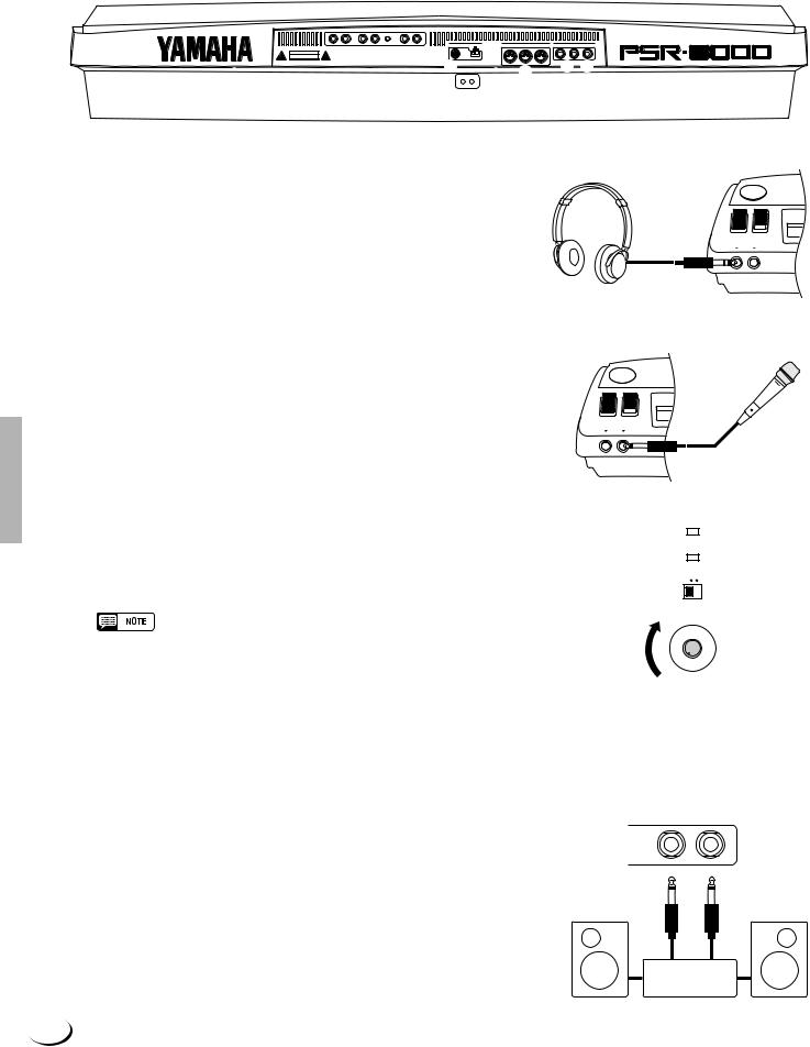
■ The PHONES Jack...............................................................................
A standard pair of stereo headphones can be plugged in here for private practice or late-night playing. The internal stereo speaker system is automatically shut off when a pair of headphones is plugged into the PHONES jack.
■ The MIC/LINE IN Jack ......................................................................
The PSR-8000 includes a microphone/line input jack into which just about any standard microphone or line-level source with a 1/4" phone plug can be plugged (a dynamic microphone with an impedance of 250 ohms is recommended). The microphone or line input can be used with the PSR-8000’s vocal harmony and sampling functions (pages 83 and 88, respectively). The panel MIC/LINE switch should be set according to the type of source used, and the INPUT VOLUME control can be used to adjust the level of the microphone or line input signal. The SIGNAL and OVER indicators on the panel aid in setting the ideal input level: the green SIGNAL indicator should light when an input signal is present, but if the red OVER indicator lights the level should be reduced by using the INPUT VOLUME control, and if this is not sufficient, by reducing the level of the source signal itself.
PHONES MIC/LINE IN
PHONES MIC/LINE IN
OVER
SIGNAL
MIC/LINE
INPUT VOLUME
• The Yamaha MZ106s microphone is recommended for use with the PSR8000.
• The level of the microphone sound may vary considerably according to the type of microphone used.
• Turn the INPUT VOLUME control all the way down when connecting or disconnecting a microphone.
• Placing a microphone which is connected to the PSR-8000 too close to the PSR-8000 speakers (or those of an external sound system connected to the PSR-8000) can cause feedback. Adjust the microphone position, and the MIXING CONSOLE MIC volume level or MASTER VOLUME control level if necessary, so that feedback does not occur.
1 The AUX OUT L/L+R and R Jacks ......................................
The rear-panel AUX OUT L/L+R and R jacks deliver the output of the PSR-8000 for connection to a keyboard amplifier, stereo sound system, a mixing console, or tape recorder. If you will be connecting the PSR-8000 to a monaural sound system, use only the L/L+R jack. When a plug is inserted into the L/L+R jack only, the leftand rightchannel signals are combined and delivered via the L/L+R jack so you don’t lose any of the PSR-8000 sound.
MIN MAX
AUX OUT
R L / L + R
Stereo System
12
,,,,,,,,,,,,,,,,,QQQQQQQQQQQQQQQQQ¢¢¢¢¢¢¢¢¢¢¢¢¢¢¢¢¢
,,,,,,,,,,,,,,,,,QQQQQQQQQQQQQQQQQ¢¢¢¢¢¢¢¢¢¢¢¢¢¢¢¢¢Connections & Music Stand
2The AUX IN L/L+R and R (LOOP RETURN)
Jacks with TRIM Control ..................................................
The rear-panel AUX IN L/L+R and R jacks accept input from an external instrument or audio source, or the processed signal returned from an external effect unit fed by the PSR-8000 LOOP SEND jacks, below. The signal received at the AUX IN/ LOOP RETURN jacks is mixed with PSR-8000 sound and delivered via the speaker system. Use the L/L+R jack only for monaural input.
The TRIM control allows the input sensitivity of the AUX IN L/L+R and R (LOOP RETURN) jacks to be adjusted for optimum level matching with the connected equipment.
AUX IN/LOOP RETURN
R L / L + R MIN MAX
TRIM
• Never return the output from the AUX OUT jacks to the AUX IN jacks. Also never return the output from an external device fed by the AUX OUT jacks to the AUX IN jacks. Doing so can result in a feedback loop which damage the PSR-8000 and connected equipment.
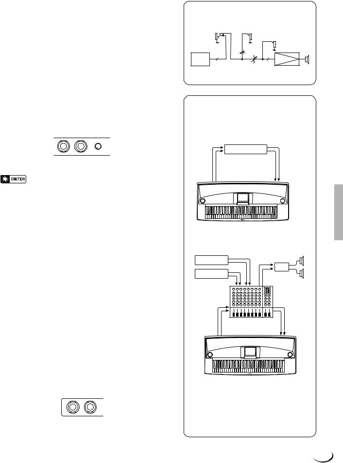
3 LOOP SEND L/L+R and R Jacks .............................
These jacks deliver the output of the PSR-8000 for connection to external signal processing devices such as reverb or equalizer units. The output from the signal processor can be returned to the AUX IN/LOOP RETURN jacks, described above. When feeding a monaural device connect only the L/ L+R jack. When a plug is inserted into the L/L+R jack only, the leftand right-channel signals are combined and delivered via the L/L+R jack.
When a plug is inserted into the LOOP SEND L/L+ R jack the internal signal flow is interrupted and only the signal returned to the AUX IN (LOOP RETURN) jacks — see above
— will appear at the PSR-8000 speakers, headphones, and AUX OUT jacks. No sound will be produced if the return signal is not fed to the AUX IN (LOOP RETURN) jacks.
LOOP SEND
R L / L + R
Loop Signal Flow Diagram
LOOP SEND |
|
AUX IN / LOOP RETURN |
|
|
|
AUX OUT |
|
L / R |
TRIM |
L / R |
|
MASTER EQ |
|
POWER AMP |
|
|
|
MASTER VOLUME |
SP |
|
|
|
LOOP SEND/LOOP RETURN
Connection Examples
1. Stereo Effect Processor
|
Effector |
LOOP SEND |
LOOP RETURN |
L/L+R R |
L/L+R R |
2. Mixer and Additional Sources
Sound Source
|
PA |
|
Sound Source |
|
|
IN PUT |
STEREO OUT |
|
IN PUT |
MONITOR |
|
OUT |
||
|
||
|
Mixer |
|
LOOP SEND |
LOOP RETURN |
|
L/L+R R |
L/L+R R |
In this setup the sound of the PSR-8000 itself as well as the external sources will be reproduced via the PSR-8000 amplifier and speakers, allowing the PSR-8000 to function as a convenient stage monitor system.
13
,,,,,,,,,,,,,,,,,QQQQQQQQQQQQQQQQQ¢¢¢¢¢¢¢¢¢¢¢¢¢¢¢¢¢
,,,,,,,,,,,,,,,,,QQQQQQQQQQQQQQQQQ¢¢¢¢¢¢¢¢¢¢¢¢¢¢¢¢¢Connections & Music Stand
4 FOOT PEDAL SWITCH 1 and 2 Jacks ...................................................................................................................
One or two optionalYamaha FC5 footswitches connected to these jacks can be used to control sustain and a range of other important functions. Refer to the “FOOT SWITCH 1” and “FOOT SWITCH 2” functions described on page 124.
FOOT PEDAL
SWITCH 1 SWITCH 2 VOLUME
5 FOOT PEDAL VOLUME Jack ...........................................................................................................................................
An optional Yamaha FC7 Foot Controller can be connected to this jack to allow foot volume (expression) control. The foot controller can be assigned to control overall volume or the volume of individual accompaniment and/or voices via the “FOOT VOLUME” function — page 124.
FOOT PEDAL
SWITCH 1 SWITCH 2 VOLUME
6 MIDI IN, THRU and OUT Connectors ......................................................................................................................
The MIDI IN connector receives MIDI data from an external MIDI device (such as a MIDI sequencer) which can be used to control the PSR-8000. The MIDI THRU connector retransmits any data received at the MIDI IN connector, allowing “chaining” of several MIDI instruments or other devices. The MIDI OUT connector transmits MIDI data generated by the PSR-8000 (e.g. note and velocity data produced by playing the keyboard). More details on MIDI are provided on pages 132, 177. The PSR-8000 can also be connected directly to a personal computer via the TO HOST connector, described below, without the need for a MIDI interface.
•Be sure to set the HOST SELECT switch to MIDI when using the MIDI connectors. The MIDI connectors do not function when the HOST SELECT switch is in any other position.
•No MIDI transmission or reception occurs in the SAMPLING mode.
MIDI
IN OUT THRU
Tone Generator
Music
Computer
14
,,,,,,,,,,,,,,,,,QQQQQQQQQQQQQQQQQ¢¢¢¢¢¢¢¢¢¢¢¢¢¢¢¢¢
,,,,,,,,,,,,,,,,,QQQQQQQQQQQQQQQQQ¢¢¢¢¢¢¢¢¢¢¢¢¢¢¢¢¢Connections & Music Stand
7 TO HOST Connector & HOST SELECT Switch ...........................................................................................
Although the PSR-8000 can be connected to a personal computer via the MIDI IN/OUT connectors and a MIDI interface, the TO HOST connector and HOST SELECT switch allow direct connection to Apple Macintosh or IBM PC/AT personal computers for sequencing and other music applications without the need for a separate MIDI interface.
•When using the [TO HOST] terminal of the PSR-8000, first turn the power off on both the PSR-8000 and the computer before connecting the cable. After connecting the cable, turn the power of the computer on first, then the PSR-8000.
•When not using the [TO HOST] terminal of the PSR-8000, make sure the cable is disconnected from the [TO HOST] terminal. If the cable is left connected, the PSR-8000 may not function properly.
•When the HOST SELECT switch is set to “Mac”, “PC-1”, or “PC-2, no data transfer occurs via the MIDI connectors. To use the MIDI connectors for connection via a standard MIDI interface, set the HOST SELECT switch to “MIDI”.
•No MIDI or TO HOST transmission or reception occurs in the SAMPLING mode.
● Connecting to an Apple Macintosh Series Computer ..................................................................
Connect the TO HOST connector of the PSR-8000 to the modem or printer port on your Macintosh, depending on which port your MIDI software is using for MIDI data communication, using a standard Macintosh 8-pin system peripheral cable. Set the HOST SELECT switch to the “Mac” position.
You may also have to make other MIDI interface settings on the computer side, depending on the type of software you use (refer to your software owner’s manual). In any case the clock speed should be set to 1 MHz.
TO HOST |
“Mac” Cable Connections |
|
|
|
||
PC-1 PC-2 |
|
|
|
|||
Mac MIDI |
|
|
|
|
|
|
Set to the “Mac” |
MINI DIN |
1 |
2 |
(HSK i) |
MINI DIN |
|
2 |
1 |
(HSK 0) |
||||
8-PIN |
8-PIN |
|||||
position. |
|
3 |
5 |
(RxD-) |
|
|
|
4 |
4 GND |
|
|||
|
|
|
||||
|
|
5 |
3 |
(TxD-) |
|
|
|
|
6 |
8 |
(RxD+) |
|
|
Apple Macintosh |
|
7 |
7 |
(GP i) |
|
|
|
8 |
6 |
(TxD+) |
|
||
Series Computer |
|
|
|
|
|
|
•8-pin system peripheral cable.
•Data transfer rate: 31,250 bps.
●Connecting to an IBM-PC/AT Series Computer ...................................................................................
Connect the TO HOST connector of the PSR-8000 to the RS-232C port on your IBM computer, using a standard 8-pin MINI DIN → 9-pin D-SUB cross cable. Set the HOST SELECT switch to the “PC-2” position.
Refer to your software owner’s manual for information on any settings you might have to make on the computer side.
TO HOST |
“PC-2” Cable Connections |
|
|
|
||
|
|
|
|
|
|
|
PC-1 PC-2 |
|
|
|
|
|
|
Mac MIDI |
|
|
|
|
|
|
|
|
MINI DIN |
|
|
|
|
Set to the “PC-2” |
|
8-PIN |
1 |
8 |
(CTS) |
D-SUB |
|
|
2 |
7 |
(RST) |
||
position. |
|
|
3 |
2 |
(RxD) |
9-PIN |
|
|
|
||||
|
|
4 |
5 |
(GND) |
|
|
|
|
|
|
|||
|
|
|
8 |
|
|
|
|
|
|
5 |
3 |
(TxD) |
|
IBM-PC/AT |
|
8-pin mini DIN → 9-pin D-SUB cable. |
|
|
|
|
Series Computer |
• |
|
|
|
||
• Data transfer rate: 38,400 bps.
15
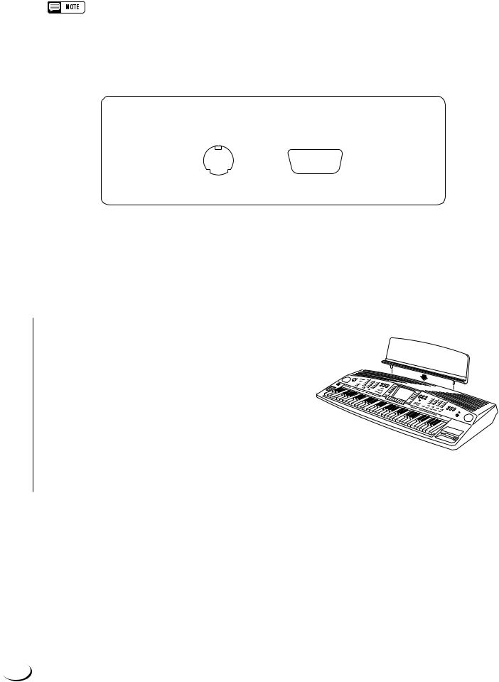
,,,,,,,,,,,,,,,,,QQQQQQQQQQQQQQQQQ¢¢¢¢¢¢¢¢¢¢¢¢¢¢¢¢¢
,,,,,,,,,,,,,,,,,QQQQQQQQQQQQQQQQQ¢¢¢¢¢¢¢¢¢¢¢¢¢¢¢¢¢Connections & Music Stand
•If your system doesn’t work properly with the connections and settings listed above, your software may require different settings. Check your software operation manual and if it requires a 31,250 bps. data transfer rate, set the HOST SELECT switch to “PC-1”.
•When using the TO HOST terminal to connect to a personal computer using Windows, a Yamaha MIDI driver must be installed in the personal computer. The Yamaha MIDI driver can be obtained at Yamaha’s home page on the World Wide Web, <http:// www.yamaha.co.jp/english/xg/>.
Connector Pin Numbers
MINI DIN 8-PIN |
D-SUB 9-PIN |
|||||
6 |
7 8 |
5 |
4 |
3 |
2 |
1 |
3 4 |
5 |
9 |
8 |
7 |
|
6 |
1 |
2 |
|
||||
|
|
|
|
|
||
■ The Music Stand ..........................................................................................................................................................................
The PSR-8000 is supplied with a music stand that can be attached to the instrument by inserting it into the holes at the rear of the speaker panel.
16
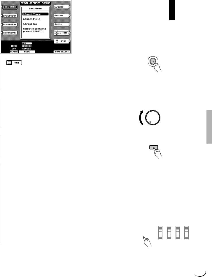
¢¢¢¢¢¢¢¢¢¢¢¢¢¢¢¢¢QQQQQQQQQQQQQQQQQ,,,,,,,,,,,,,,,,,
¢¢¢¢¢¢¢¢¢¢¢¢¢¢¢¢¢QQQQQQQQQQQQQQQQQ,,,,,,,,,,,,,,,,,
The Demonstration
¢¢¢¢¢¢¢¢¢¢¢¢¢¢¢¢¢QQQQQQQQQQQQQQQQQ,,,,,,,,,,,,,,,,,
To give you an idea of the PSR-8000’s sophisticated capabilities, it is programmed with a number of demonstration sequences which can be played in a number of ways.
ZSwitch ON ............................................................................................................................................................................................
Plug the AC power cord into the AC INLET on the rear panel of the PSR-8000, and a convenient AC outlet, then press the [STANDBY] button to turn the PSR-8000 ON.
 STAND BY
 ON
ON
• Pressing the [STANDBY] button a second time turns the power off.
•Even when the power is “off”, the PSR-8000 consumes a minute amount of power in order to maintain some internal memory contents. Be sure to unplug the AC power cord from the AC outlet if you will not be using the PSR-8000 for a long time.
XSet an Initial Volume Level ................................................................................................................................................
Set the [MASTER VOLUME] control to a position about a quarter of the way toward the highest setting. You can re-adjust the [MASTER VOLUME] control for the most comfortable overall volume level after playback begins.
MASTER VOLUME
MIN MAX
CPress the [DEMO/HELP] Button ..................................................................................................................................
Press the [DEMO/HELP] button and the PSR-8000 demo |
DEMO/HELP |
display will appear. |
|
VSelect a Play Mode .................................................................................................................................................................... |
|
Use either of the LCD dials under MODE on the display to select one of the available play modes.
ALL |
All demo songs are played back in sequence. |
|
|
|
|
|
|
|
|
|
|
|
|
|
|
|
|
|
|
RANDOM |
All demo songs are played back in random order. |
|
|
|
|
|
|
|
|
|
|
|
|
|
|
|
|
|
|
SINGLE |
Only the selected song is played. |
|
|
|
|
|
|
|
|
|
|
|
|
|
|
|
|
|
|
|
|
|
|
|
|
|
|
|
|
|
|
|
|
|
|
|
|
|
|
|
|
|
|
|
|
|
|
|
|
|
|
|
|
|
|
|
|
|
|
17
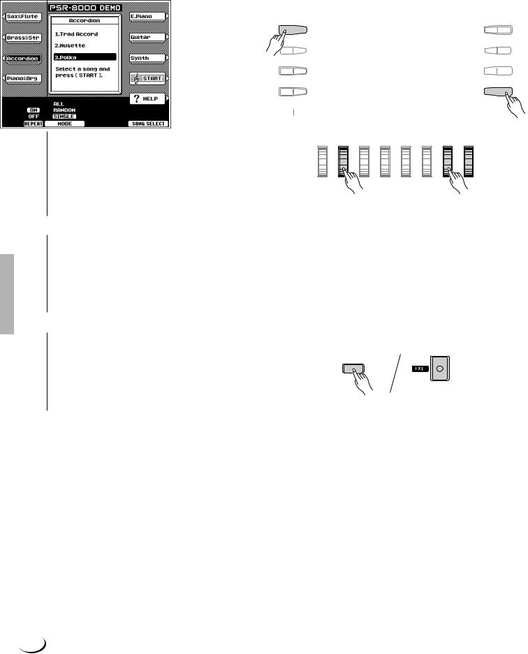
,,,,,,,,,,,,,,,,,QQQQQQQQQQQQQQQQQ¢¢¢¢¢¢¢¢¢¢¢¢¢¢¢¢¢
,,,,,,,,,,,,,,,,,QQQQQQQQQQQQQQQQQ¢¢¢¢¢¢¢¢¢¢¢¢¢¢¢¢¢The Demonstration
BSelect a Song ..................................................................................................................................................................................
Press the LCD button corresponding to the category containing of demo song you want to play, then use the same LCD button to select a demo song in that group. You can also use either of the LCD dials under SONG SELECT on the display to select any of the demo songs.
NTurn the Repeat Mode ON or OFF
Use the REPEAT LCD dial to turn repeat playback ON or OFF as required (when ON, the selected song or sequence of songs will be repeated until the STOP LCD button is pressed)
MStart & Stop Playback as Re-
quired .........................................................................
A 
 F
F
B
 G
G
C  H
H
D  I E
I E 
 MJ
MJ
NB
Press the START LCD button to start playback of the selected demo song(s). Press the STOP LCD button when you want to stop playback.
<Exit When Done .............................................................................................................................................................................
Press either the [DEMO/HELP] button or the
[EXIT] button to exit from the demo mode and
DEMO/HELP
return to the normal play-mode display when you’ve finished playing the demo songs.
18
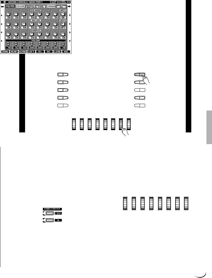
¢¢¢¢¢¢¢¢¢¢¢¢¢¢¢¢¢QQQQQQQQQQQQQQQQQ,,,,,,,,,,,,,,,,,
¢¢¢¢¢¢¢¢¢¢¢¢¢¢¢¢¢QQQQQQQQQQQQQQQQQ,,,,,,,,,,,,,,,,,
The PSR-8000 Display & Display-based Controls
¢¢¢¢¢¢¢¢¢¢¢¢¢¢¢¢¢QQQQQQQQQQQQQQQQQ,,,,,,,,,,,,,,,,,
The PSR-8000 makes general operation and programming easier than ever with a large backlit LCD display panel and multi-function controls. The 10 LCD (A—J) buttons — five on either side of the display panel — and 8 LCD dials below the display perform the function indicated by the adjacent section of the display.
In the example display shown here, for example, the LCD dial immediately below LEAD on the display can be used to adjust the volume of the LEAD voice. Rotate the dial upward to increase the volume, or rotate the dial downward to decrease the volume.
In the same way, the LCD button immediately to the right of LEAD voice window on the display is used to set the normal octave for the lead voice (“0”), shift it one octave up (“+1”), or one octave down (“–1”).
A F
B G
C  H
H
D I
E 
 J
J
■ The MIXING CONSOLE Buttons ..............................
The lower section of the normal play mode display, shown to the right, provides individual volume controls for the PSR8000’s song, accompaniment, multi pad, left, right 1, right 2, lead, and microphone sound. Pressing the [FADER] button alternately switches between this display and the individual auto-accompaniment part volume controls: rhythm 1, rhythm 2, bass, chord 1, chord 2, pad, phrase 1, and phrase 2. This is essentially a “mixer” that you will use to achieve the best overall balance for your musical needs.
PART
PART
A full-screen mixing console which provides access to a wide range of controls for each part can be selected by pressing the [FULL] button. Full details are provided in the “The Mixing Console” section on page 39.
19
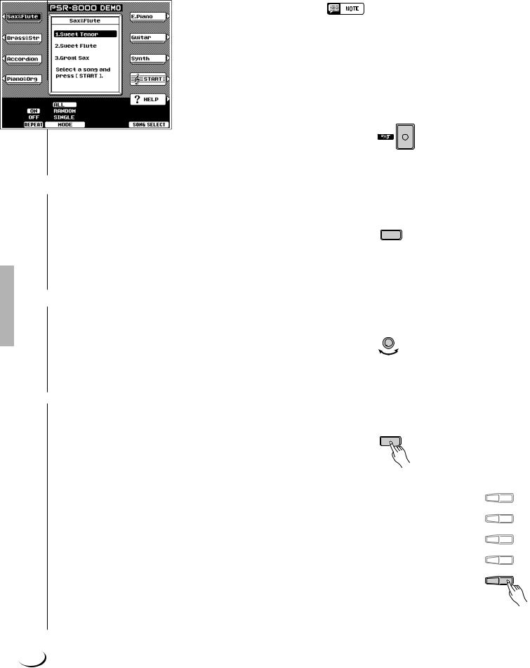
,,,,,,,,,,,,,,,,,QQQQQQQQQQQQQQQQQ¢¢¢¢¢¢¢¢¢¢¢¢¢¢¢¢¢
,,,,,,,,,,,,,,,,,QQQQQQQQQQQQQQQQQ¢¢¢¢¢¢¢¢¢¢¢¢¢¢¢¢¢The PSR-8000 Display & Display-based Controls
The mixing console controls will disappear when functions which have different displays are selected, but can be instantly recalled without exiting from the current display mode by pressing the [FADER] or [FULL] button. Pressing the [EXIT] button causes the mixer controls to disappear.
•In the DEMO mode the mixer SONG parameters become DEMO parameters.
■ The [EXIT] Button .......................................................................................................................................................................
No matter where you are in the PSR-8000 display hierarchy, the [EXIT] button will return you to the next highest level, or to the normal play mode display.
■ The [DIRECT ACCESS] Button .....................................................................................................................................
Pressing a function button while holding the [DIRECT ACCESS] button will take you directly to a parameter display related to that function. See page 170 for a list of the applicable panel buttons and parameter displays accessed.
DIRECT ACCESS
■ The [LCD CONTRAST] Control ....................................................................................................................................
The PSR-8000 display panel is a liquid-crystal type which features a [LCD CONTRAST] control. Use the [LCD CONTRAST] control to set the display for optimum legibility.
LCD CONTRAST
■ The 5-language Help Function .....................................................................................................................................
The PSR-8000 provides “on-line help” for its main |
DEMO/HELP |
features and functions. |
|
Press the [DEMO/HELP] button and then the HELP |
|
LCD button to go to the main help display. Either select |
|
an item from the HELP MENU by using one of the |
|
corresponding LCD dials and then press the “ ENTER” |
|
LCD button, or simply press a panel button to see |
|
corresponding help text. If more than one page of help |
|
text is available for the selected topic, use the LCD |
|
buttons to the right of the display to switch pages as |
|
necessary. Press the RETURN TO HELP MENU LCD |
|
button for more help, or the [EXIT] or [DEMO/HELP] |
|
button when you’re ready to exit from the help mode. |
|
F
G
H
I
J
20
,,,,,,,,,,,,,,,,,QQQQQQQQQQQQQQQQQ¢¢¢¢¢¢¢¢¢¢¢¢¢¢¢¢¢
,,,,,,,,,,,,,,,,,QQQQQQQQQQQQQQQQQ¢¢¢¢¢¢¢¢¢¢¢¢¢¢¢¢¢The PSR-8000 Display & Display-based Controls
Help text and screen messages are available in five languages: English, German, French, Spanish, and Italian. Use the LANGUAGE LCD dials in the help display to select the desired language.
F
G
H
I
J
■ Display Messages.......................................................................................................................................................................
The large PSR-8000 display panel facilitates operation by making it possible to display comprehensive message and prompts that will guide you through certain operations. When such messages appear, simply follow the instructions as shown.
■ Name Entry ........................................................................................................................................................................................
A number of PSR-8000 functions allow you to enter a name for, for example, a file you will be saving to disk, a custom voice or style, etc. The name entry procedure is essentially the same in all cases (only the maximum number of characters which can be entered will vary). An example display which includes NAME entry parameters is shown below (the display shown below can be accessed by pressing one of the REGISTRATION MEMORY buttons — [1] … [8] — while holding the
[DIRECT ACCESS] button):
Use the < > LCD dial to move the name cursor to the various character positions, then use the A~Z, a~z, or 0~9… LCD dial to select the required character for each position. The A~Z LCD dial selects capital letters, the a~z LCD dial selects lower-case letters, and the 0~9… LCD dial selects numbers and special characters.
21

¢¢¢¢¢¢¢¢¢¢¢¢¢¢¢¢¢QQQQQQQQQQQQQQQQQ,,,,,,,,,,,,,,,,,
¢Q,,¢¢¢¢¢¢¢¢¢¢¢¢¢¢¢¢QQQQQQQQQQQQQQQQ,,,,,,,,,,,,,,,,
Playing the PSR-8000
¢¢¢¢¢¢¢¢¢¢¢¢¢¢¢¢¢¢QQQQQQQQQQQQQQQQQQ,,,,,,,,,,,,,,,,,,
Before You Begin
Before playing your PSR-8000 for the first time, it might be a good idea to re-initialize it to the original factory settings just in case these have been changed at some point before you receive the instrument. To do this, turn the [STANDBY] switch ON while holding the rightmost key on the keyboard (C6).
• When the above initialization procedure is carried out, all internal data (e.g. REGISTRATION, CUSTOM OTS (One Touch Setting), CUSTOM STYLE, GROOVE STYLE, CUSTOM VOICE, MULTI PAD) will also be initialized and therefore lost!
The PSR-8000 Parts & Voices
The PSR-8000 allows you to individually select and play up to four “parts” at the same time in a number of ways. A range of voices can be assigned to each part.
RIGHT 1, The RIGHT 1, RIGHT 2, and LEAD voices can be played over the entire keyboard or to the right of a RIGHT 2, specified split point (see “NOTE”, below). These voices can be played individually or in any combination. & LEAD The RIGHT 1, RIGHT 2, and LEAD voices can be selected from a range of voices organized in 15 groups.
LEFT The LEFT can be played to the left of a specified split point while the RIGHT 1, RIGHT 2, and/or LEAD voices are played to the right of the split point. The LEFT voice can be selected from the same range of voices as the RIGHT and LEAD parts.
•The split point can be set via the SPLIT POINT/FINGERING FUNCTION display described on page 123.
•The SPLIT POINT/FINGERING FUNCTION display can be accessed directly by pressing the [AUTO ACCOMPANIMENT] button while holding the [DIRECT ACCESS] button.
■Part Poly/Mono Modes & Mono Note Priority ...............................................................................................
Each of the PSR-8000 voice “parts” can be switched to the polyphonic or monophonic mode as required via the PART SWITCH display accessed by pressing the PART LCD button in the normal play mode while the FADER mixer MAIN PART display is selected (page 19).
Use the LEFT, RIGHT 1, RIGHT 2, and LEAD LCD dials to set the corresponding parts to POLY (polyphonic) or any of the three MONO (monophonic) note priority modes:
22
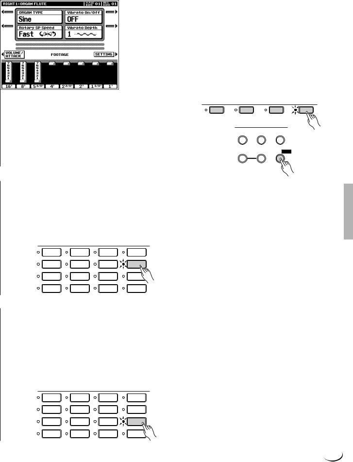
,,,,,,,,,,,,,,,,,QQQQQQQQQQQQQQQQQ¢¢¢¢¢¢¢¢¢¢¢¢¢¢¢¢¢
,,,,,,,,,,,,,,,,,QQQQQQQQQQQQQQQQQ¢¢¢¢¢¢¢¢¢¢¢¢¢¢¢¢¢Playing the PSR-8000
AUTO |
When all other parts as set to MONO, last-note |
|
priority is automatically selectd. When at least one |
|
other part is set to POLY, high-note priority is |
|
automatically selected. |
|
|
HIGH |
High-note priority. I.e. the highest note played on |
|
the keyboard sounds. |
|
|
LAST |
Last-note priority. I.e. the last note played sounds. |
|
|
Poly/mono switching for each individual part can also be carried out via the panel VOICE EFFECT [POLY/MONO] button. Use the PART SELECT buttons to select the part you want to switch, then use the [POLY/MONO] button to switch selected part to the POLY (button indicator out) or MONO (button indicator lit) mode. When the MONO mode is selected via the [POLY/MONO] button, the last selected MONO note priority mode will be selected.
PART SELECT
LEFT |
RIGHT 1 |
RIGHT 2 |
VOICE EFFECT
HARMONY/
REVERB(1) CHORUS(2) ECHO
DSP
DSP(4-6) VARIATION POLY/

■ The XG Voices .................................................................................................................................................................................
Yamaha’s XG format is a major new enhancement to the GM (General MIDI) System Level 1 format. It provides a larger number of voices as well as greater expressive control and a wide range of effects. XG also ensures continued compatibility with future instruments and software.
|
VOICE |
|
|
|
PIANO |
GUITAR |
SAXOPHONE |
PERCUSSION |
|
E.PIANO |
STRINGS |
FLUTE |
XG |
|
ORGAN |
TRUMPET |
CHOIR&PAD |
ORGAN |
|
FLUTE |
||||
|
|
|
||
ACCORDION |
BRASS |
SYNTHESIZER |
CUSTOM |
|
VOICE |
||||
|
|
|
||
■ The Organ Flute Voice ............................................................................................................................................................ |
|
|
||
The PSR-8000 has an ORGAN FLUTE voice which can be assigned to the RIGHT, LEAD and LEFT voices in the same way as the other voices. The main difference between the ORGAN FLUTE voice and others is that the ORGAN FLUTE voice can be directly edited via the display accessed by pressing the [ORGAN FLUTE] VOICE button. Details on editing the ORGAN FLUTE voice are provided on page 48.
VOICE
PIANO |
GUITAR |
SAXOPHONE |
PERCUSSION |
|
E.PIANO |
STRINGS |
FLUTE |
XG |
|
ORGAN |
TRUMPET |
CHOIR&PAD |
ORGAN |
|
FLUTE |
||||
|
|
|
||
ACCORDION |
BRASS |
SYNTHESIZER |
CUSTOM |
|
VOICE |
||||
|
|
|
23
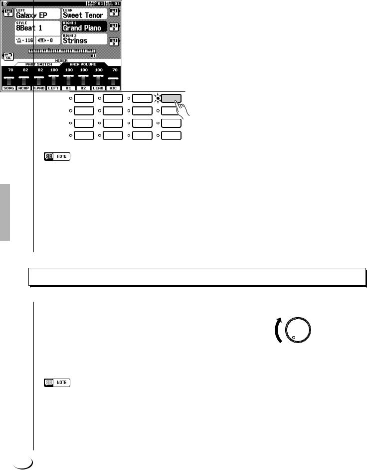
,,,,,,,,,,,,,,,,,QQQQQQQQQQQQQQQQQ¢¢¢¢¢¢¢¢¢¢¢¢¢¢¢¢¢
,,,,,,,,,,,,,,,,,QQQQQQQQQQQQQQQQQ¢¢¢¢¢¢¢¢¢¢¢¢¢¢¢¢¢Playing the PSR-8000
■ Keyboard Percussion and Special Effects ......................................................................................................
When one of the Drum Kit or SFX Kit voices in the [PERCUSSION] group is selected, you can play 61 different drums and percussion instruments or SFX (special effects) sounds on the keyboard. The drum and percussion instruments played by the various keys are marked by symbols above the keys. Some of the instruments in the different drum kit voices sound different even though they have the same name, while others are essentially the same.
VOICE
PIANO |
GUITAR |
SAXOPHONE |
PERCUSSION |
|
E.PIANO |
STRINGS |
FLUTE |
XG |
|
ORGAN |
TRUMPET |
CHOIR&PAD |
ORGAN |
|
FLUTE |
||||
|
|
|
||
ACCORDION |
BRASS |
SYNTHESIZER |
CUSTOM |
|
VOICE |
||||
|
|
|
•The instrument symbols above the keyboard correspond to the actual instrument sounds only when the default MIXER and normal play mode OCTAVE settings apply. If the OCTAVE settings are altered the instruments will shift position accordingly.
•See page 166 for a complete listing of the Drum Kit and SFX Kit assignments.
•The Transpose, Tune, Sustain, Harmony, Left Hold, and Modulation functions do not affect the Drum Kit or SFX Kit voices.
•The pitch bend wheel can be used to bend the pitch of the keyboard percussion and SFX voices to create unique musical effects, but it has little effect on some percussion sounds.
Procedure: Part Selection and Voice Assignment
ZSet Initial Volume Levels .....................................................................................................................................................
Set the [MASTER VOLUME] control to an appropriate level, and make sure that the LEFT, R1, R2, and LEAD volume levels in the MIXING CONSOLE MAIN VOLUME display are set to their maximum “127” levels (use the corresponding LCD dials to set these volume levels if necessary). You can set the [MASTER VOLUME] control for the most comfortable overall volume level after beginning to play.
•No sound will be produced if all volume levels other than the [MASTER VOLUME] control are set to their minimum values.
MASTER VOLUME
MIN MAX
24
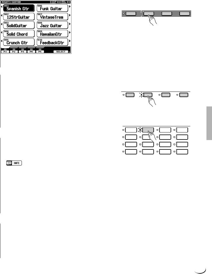
,,,,,,,,,,,,,,,,,QQQQQQQQQQQQQQQQQ¢¢¢¢¢¢¢¢¢¢¢¢¢¢¢¢¢
,,,,,,,,,,,,,,,,,QQQQQQQQQQQQQQQQQ¢¢¢¢¢¢¢¢¢¢¢¢¢¢¢¢¢Playing the PSR-8000
XSelect the Parts You Want To Play .............................................................................................................................
Press the [RIGHT 1], [RIGHT 2], [LEAD], and/or [LEFT] PART ON/OFF button(s), turning on the indicators corresponding to the parts you want to play. When a part is turned on the corresponding voice in the main play mode display will be highlighted (i.e. inverted — white characters against a dark background).
•The more parts you play simultaneously, the fewer the total number of notes that can be played on the keyboard at the same time.
•When the LEFT part is on, the left voice will automatically be transposed up one octave.
PART ON/OFF
LEFT  RIGHT 1
  RIGHT 2
  LEAD
LEAD
CSelect the Part You Want to Assign a Voice To.............................................................................................
The PART SELECT buttons above the PART ON/OFF buttons determine which part is selected for voice assignments. If you want to change the voice assigned to the RIGHT 1 part, for example, the [RIGHT 1] PART SELECT indicator must be lit. Each time you turn a part on using the PART ON/OFF buttons, the corresponding PART SELECT button indicator will light automatically. You can also directly press any of the PART SELECT buttons. Only one PART SELECT button can be active at a time.
VSelect a Voice ..............................................................................
Use the VOICE group buttons to select the group from which you want to select a voice. The corresponding voice display will appear.
PART SELECT
LEFT |
RIGHT 1 |
RIGHT 2 |
LEAD |
VOICE
PIANO |
GUITAR |
SAXOPHONE |
PERCUSSION |
|
E.PIANO |
STRINGS |
FLUTE |
XG |
|
ORGAN |
TRUMPET |
CHOIR&PAD |
ORGAN |
|
FLUTE |
||||
|
|
|
||
ACCORDION |
BRASS |
SYNTHESIZER |
CUSTOM |
|
VOICE |
||||
|
|
|
•Custom voices which can be selected via the [CUSTOM VOICE] button can be created via the CUSTOM VOICE CREATOR mode described on page 51, or loaded from disk.
Use the page-number LCD dials to select the page containing the voice you want if more than one page is available, then press the LCD button corresponding to the desired voice. You can also use either of the SELECT LCD dials to select any of the voices within the selected group.
BPlay & Adjust Volume .............................................................................................................................................................
You can now play the selected voice or voices on the keyboard. Use the [MASTER VOLUME] control to adjust the overall volume level, and the MIXING CONSOLE MAIN VOLUME LCD dials to set the desired balance between the parts.
25
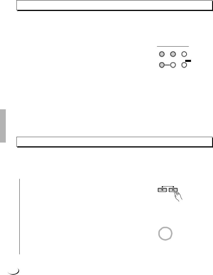
,,,,,,,,,,,,,,,,,QQQQQQQQQQQQQQQQQ¢¢¢¢¢¢¢¢¢¢¢¢¢¢¢¢¢
,,,,,,,,,,,,,,,,,QQQQQQQQQQQQQQQQQ¢¢¢¢¢¢¢¢¢¢¢¢¢¢¢¢¢Playing the PSR-8000
Voice Effects
The PSR-8000 features a sophisticated multi-processor effect system which can add extraordinary depth and expression to your sound. 7 independent digital signal processing (DSP) blocks are provided for effects, plus the Vocal Harmony processor and 5-band Master EQ. Each DSP block applies to a specific part or portion of the PSR8000 sound. Some DSP block numbers appear next to the panel VOICE EFFECT buttons:
REVERB(1) |
Overall reverb |
|
|
CHORUS(2) |
Overall chorus. |
|
|
DSP(4-6) |
Independent effects for the RIGHT 1, RIGHT 2, |
|
and LEAD parts. |
|
|
VOICE EFFECT
HARMONY/ REVERB(1) CHORUS(2) ECHO
DSP
DSP(4-6) VARIATION POLY/

There’s also a DSP VARIATION effect which can be applied to DSP(4-6) when the DSP(4-6) effect is on. The VOICE EFFECT buttons turn the corresponding effects on (indicator lit) or off (indicator out) for the part currently selected via the PART SELECT buttons. Independent VOICE EFFECT settings can be made for each part. You can use the default effects, or reprogram them as required via the FULL MIXING CONSOLE, EFFECT DEPTH and EFFECT TYPE displays (pages 41, 42).
The HARMONY/ECHO effect is described on page 37, and the operation of the POLY/MONO button is described on page 22.
Other Play Mode Functions
The Master Transpose and Octave Change functions described here allow you to change the overall pitch of the PSR8000, or the octave of individual parts as required. The Left Hold function can be used to provide extra LEFT part sustain.
■ Master Transpose ........................................................................................................................................................................
This functions allow the overall pitch of the PSR-8000 to be transposed up or down over a range of ±2 octaves in semitone steps.
Use the MASTER TRANSPOSE [<] and [>] buttons to set the transposition value as required. The current amount of transposition appears in the transpose section of the normal play mode display: from “ –24” through “ 0” to “ +24”.
Normal pitch (transpose value “0”) can be recalled at any time by pressing both the MASTER TRANSPOSE [<] and [>] buttons simultaneously.
RESET
MASTER
TRANSPOSE
26
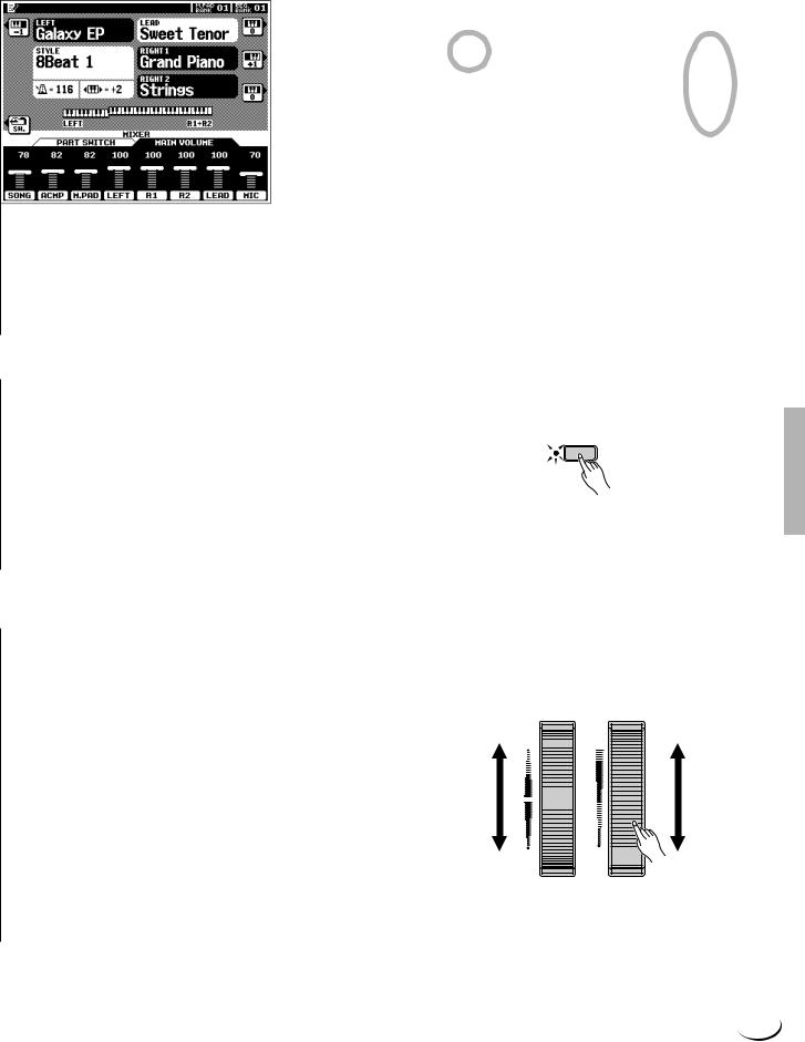
,,,,,,,,,,,,,,,,,QQQQQQQQQQQQQQQQQ¢¢¢¢¢¢¢¢¢¢¢¢¢¢¢¢¢
,,,,,,,,,,,,,,,,,QQQQQQQQQQQQQQQQQ¢¢¢¢¢¢¢¢¢¢¢¢¢¢¢¢¢Playing the PSR-8000
■ Octave Change ..............................................................................................................................................................................
This function allows the LEFT, RIGHT 1, RIGHT2, and LEAD parts to be independently transposed up or down by one octave.
The LEFT, RIGHT1, RIGHT2, LEAD LCD buttons (with the small keyboard icons) directly set the octave of the corresponding part to “ +1”, “ –1”, and then “ 0”, in sequence.
•These parameters are separate from the OCTAVE parameters accessed via the FULL mixing console display (page 44). The values of these octave parameters are added to those of the mixer’s OCTAVE parameters.
•Some voices may suddenly shift octaves when played at the extreme ends of the keyboard if they are set to a lower or higher octave and/or transpose value than normal. This can also occur when the PITCH BEND wheel is used on extremely low or high notes.
•If you change the transpose or octave change settings while playing one or more notes on the keyboard, the new settings will take effect from the next notes played.
■Left Hold ...............................................................................................................................................................................................
This function causes the LEFT part voice to be held even when the keys are released. Non-decaying voices such as strings are held continuously, while decay-type voices such as piano decay more slowly (as if the sustain pedal has been pressed). Press the [LEFT HOLD] button so that its indicator lights to engage the LEFT HOLD function. Press the [LEFT HOLD] button a second time so that the indicator goes out to turn LEFT HOLD off.
 LEFT HOLD
■ Pitch Bend & Modulation Wheels ..............................................................................................................................
The PITCH BEND and MODULATION wheels to the left of the PSR-8000 keyboard can be used to add expressive variation to your sound.
The range of the PITCH BEND wheel can be indpendently set for the LEFT, RIGHT 1, RIGHT 2, and LEAD parts via the
FULL MIXING CONSOLE TUNING display (page 44). The type of modulation applied by the MODULATION
wheel is preset for each of the PSR-8000’s preset voices. You can assign your own modulation effects when creating CUSTOM VOICE (page 51). The MODULATION wheel can be independently turned on or off for the LEFT, RIGHT 1, RIGHT 2, and LEAD parts via the F3: CONTROLLER, PANEL CONTROLLER display (page 126).
PITCH BEND MODULATION
UP  MAX
MAX
DOWN |
MIN |
27
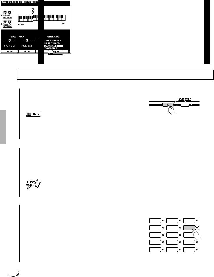
¢¢¢¢¢¢¢¢¢¢¢¢¢¢¢¢¢QQQQQQQQQQQQQQQQQ,,,,,,,,,,,,,,,,,
¢Q,,¢¢¢¢¢¢¢¢¢¢¢¢¢¢¢¢QQQQQQQQQQQQQQQQ,,,,,,,,,,,,,,,,
Using the Accompaniment Section
¢¢¢¢¢¢¢¢¢¢¢¢¢¢¢¢¢¢QQQQQQQQQQQQQQQQQQ,,,,,,,,,,,,,,,,,,
The PSR-8000 has 214 different preset accompaniment “styles” that can be used to provide fully-orchestrated or rhythm-only accompaniment. You can also create your own “custom” and “groove” styles, as described on pages 62 and 76, respectively. Up to 16 custom styles and 20 groove styles can be retained in the PSR8000 memory — more can be saved to disk for later loading and use.
The PSR-8000’s sophisticated auto-accompaniment system can provide automated bass and chord backing that is perfectly matched to the selected accompaniment style.
•The supplied floppy disk includes additional style files which can be used after being loaded into the PSR8000 (see page 140 for loading instructions).
Procedure: Auto Accompaniment
ZTurn AUTO ACCOMPANIMENT ON ...........................................................................................................................
Press the [AUTO ACCOMPANIMENT] button so that its indicator lights, thereby turning the AUTO ACCOMPANIMENT mode on.
AUTO
ACCOMPANIMENT
•Rhythm-only accompaniment will be produced if you don’t turn the [AUTO ACCOMPANIMENT] button on.
•The maximum number of notes that can be played simultaneously on the PSR-8000 keyboard is reduced when the AUTO ACCOMPANIMENT feature is used.
XSelect the Desired Fingering Mode .....................
Select the desired auto accompaniment fingering mode via the SPLIT POINT/FINGERING FUNCTION display described on page 123. The operation of each mode is described in “Auto Accompaniment Fingering Modes”, page 30.
• Press the [AUTO ACCOMPANIMENT] button while holding the [DIRECT ACCESS] button to jump directly to the SPLIT POINT/FINGERING display (page 123).
CSelect a Style ...................................................................................................................................................................................
The PSR-8000 has 214 preset styles organized in 13 groups (see the “Style List” on page 168).
Use the STYLE group buttons to select the group from which you want to select a style. The corresponding style display will appear.
Use the page-number LCD dials to select the page containing the style you want if more than one page is available, then press the LCD button corresponding to the desired style. You can also use either of the SELECT LCD dials to select any of the styles within the selected group.
STYLE
8BEAT 1 |
DANCEFLOOR |
LATIN |
|
8BEAT 2 |
DISCO |
BALLROOM |
|
16BEAT |
SWING & |
MARCH & |
|
JAZZ |
WALTZ |
||
|
|||
BALLAD |
R & B |
GROOVE |
|
STYLE |
|||
|
|
||
ROCK |
COUNTRY |
CUSTOM |
|
STYLE |
|||
|
|
28
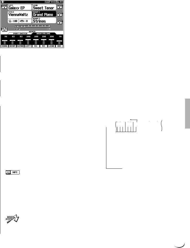
,,,,,,,,,,,,,,,,,QQQQQQQQQQQQQQQQQ¢¢¢¢¢¢¢¢¢¢¢¢¢¢¢¢¢
,,,,,,,,,,,,,,,,,QQQQQQQQQQQQQQQQQ¢¢¢¢¢¢¢¢¢¢¢¢¢¢¢¢¢Using the Accompaniment Section
The PSR-8000 automatically determines the voices to be used for the accompaniment bass and chords according to the accompaniment style you select.
•Custom and groove styles which can be selected via the [CUSTOM STYLE] and [GROOVE STYLE] buttons can be created as described on pages 62 and 76, respectively, or loaded from disk.
•Styles loaded from the floppy disk provided with the PSR-8000 or optional SFF (Style File Format) disks can also be used as CUSTOM STYLES.
VSet the Tempo .................................................................................................................................................................................
If necessary, set the playback tempo as required (see “Tempo
Control, page 35).
BStart the Accompaniment ..................................................................................................................................................
Use one of the start modes described in “Auto Accompaniment Start Modes”, below, to start the accompaniment.
NPlay On the AUTO ACCOMPANIMENT Section Of the Keyboard ............................................
As soon as you play any chord that the PSR-8000 can “recognize” on the AUTO ACCOMPANIMENT section of the keyboard (to the left of the auto accompaniment split point — F#2 by default), the PSR-8000 will automatically begin to play the chord along with the rhythm and an appropriate bass line. The accompaniment will continue playing even if you release the left-hand keys. See “AutoAccompaniment Fingering Modes”, below, for information on the individual fingering modes.
If the MANUAL BASS mode is selected only the rhythm accompaniment will play automatically, and the bass voice set for the style can be played on the AUTO ACCOMPANIMENT section of the keyboard.
•The AUTO ACCOMPANIMENT section split point can be changed via the SPLIT POINT/FINGERING FUNCTION display, described on page 123.
•The appropriate chord and bass note will sound if you play in the AUTO ACCOMPANIMENT section of the keyboard while the AUTO ACCOMPANIMENT function is on but the accompaniment is stopped (but not in the FULL KEYBOARD and MANUAL BASS modes).
•The four LED dots of the TEMPO display provide a visual indication of the selected tempo.
• The SPLIT POINT/FINGERING display can be accessed directly by pressing the [AUTO ACCOMPANIMENT] button while holding the [DIRECT ACCESS] button.
Auto Accompani- |
|
Split Point |
|
|
|
|
|
|
||||||||||||||
|
|
▼ |
|
|
|
|
|
|
||||||||||||||
ment Section |
|
|
|
|
|
|
|
|
||||||||||||||
|
|
|
|
|
|
|
|
|
|
|
|
|||||||||||
|
|
|
|
|
|
|
|
|
|
|
|
|
|
|
|
|
|
|
|
|
|
|
|
|
|
|
|
|
|
|
|
|
|
|
|
|
|
|
C3 |
|
|
|
|
|
|
|
|
|
|
|
|
|
|
|
|
|
|
|
|
|
|
|
|
|
|
|
|
|
 Melody Section
29
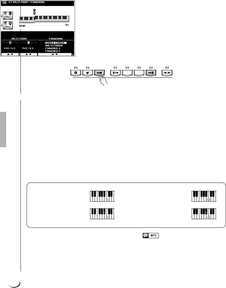
,,,,,,,,,,,,,,,,,QQQQQQQQQQQQQQQQQ¢¢¢¢¢¢¢¢¢¢¢¢¢¢¢¢¢
,,,,,,,,,,,,,,,,,QQQQQQQQQQQQQQQQQ¢¢¢¢¢¢¢¢¢¢¢¢¢¢¢¢¢Using the Accompaniment Section
MSelect the MAIN A and B Sections as Required ........................................................................................
Select the MAIN A and MAIN B sections as required. Appropriate fill-ins will be generated automatically (see “The MAIN A and MAIN B Sections and Fill-ins”, page 34).
<Stop the Accompaniment ..................................................................................................................................................
The accompaniment can be stopped at any time by pressing the [START/STOP] button. Press the [ENDING A/ B /rit.] button if you want to go to the ending section and then stop. A different ending will play depending on whether you go to the ending from the MAIN A or MAIN B section. Press the [ENDING A/B /rit.] button while the ending section is playing to produce a “ritardando” ending — i.e. the tempo gradually slows down during the ending.
SYNC |
SYNC |
START/ |
INTRO A/B |
MAIN/AUTO FILL |
ENDING A/B |
FADE |
|||||
STOP |
START |
STOP |
/rit. |
IN/OUT |
|||||||
|
|
|
|
||||||||
|
|
|
|
|
|
|
|
|
|
|
|
|
|
|
|
|
|
|
|
|
|
|
|
|
|
|
|
|
|
|
|
|
|
|
|
A B
ACCOMPANIMENT CONTROL
■ Auto Accompaniment Fingering Modes ............................................................................................................
The PSR-8000 AUTO ACCOMPANIMENT feature has six different fingering modes which can be selected via the SPLIT POINT/FINGERING FUNCTION display described on page 123. Operation of each mode is described below.
● SINGLE FINGER
Single-finger accompaniment makes it simple to produce beautifully orchestrated accompaniment using major, seventh, minor and minor-seventh chords by pressing a minimum number of keys on the AUTO ACCOMPANIMENT section of the keyboard. The abbreviated chord fingerings described below are used:
C
● For a major chord, press the root key only.
Cm
● For a minor chord, simulta-
neously press the root key and a black key to its left.
C7
●For a seventh chord, simultaneously press the root key and a white key to its left.
Cm7
● For a minor-seventh chord, simulta-
neously press the root key and both a white and black key to its left.
● MULTI FINGER
The MULTI-FINGER mode automatically detects SINGLE FINGER or FINGERED 1 chord fingerings, so you can use either type of fingering without having to switch fingering modes.
•To use SINGLE FINGER minor, minor-seventh, or seventh fingerings in the MULTI FINGER mode, be sure to play the closest white/black key(s) to the root of the chord.
30
 Loading...