


http://servis-manual.com/

http://servis-manual.com/
SECTION 4
TEST MODE
[LED All Lit, Key Check Mode]
Procedure:
1.Press the ?/1 button to turn the power ON.
2.Press three buttons of s (DECK B), A (DISC 1), and [DISC 5] simultaneously.
3.LEDs are all turned on.
Press the G (CD) button, and the key check mode is activated. LEDs are all OFF.
4.When a button is pressed, the LED near the pressed button blinks or lights up.
Also, if all buttons are pressed, all LEDs light up (not blink).
5.To release from this mode, press three buttons in the same manner as step 2, or remove the power cord.
[CD Delivery Mode]
• This mode moves the optical pick-up to the position durable to vibration. Use this mode when returning the set to the customer after repair.
Procedure:
1.Press the ?/1 button to turn the power ON.
2.Press the s (DECK B) and [DISC 1] buttons simultaneously.
3.A message “LOCK” is displayed on the liquid crystal display of the STR-NX1/NX3, and the CD delivery mode is set.
[Tape Deck Test Mode]
(In case of connected to the STR-NX1/NX3)
• If connected to the STR-NX1/NX3, the mode also acts as the STR-NX1/NX3 amplifer test mode.
Procedure:
1.Press the ?/1 button to turn the power ON.
2.Press three buttons of s (DECK B), A (DISC 1), and S (CD) simultaneously.
3.On liquid crystal display of the STR-NX1/NX3, the disc calendar blinks, and “ALC OFF” is displayed, then the function which was set before the test mode became active is displayed.
4.The automatic level control of the tape deck is in OFF status, but while the s (CD) and [REC PAUSE/START] buttons are pressed during recording, automatic level control goes in ON status.
[Tape Deck Test Mode]
(In case of connected to the power feed jig)
Procedure:
1.Turn on the Power switch on the power feed jig.
2.Press three buttons of s (DECK B), A (DISC 1), and s (CD) simultaneously.
3.The G (CD) and S (CD) LEDs blink, and then pressing G (CD), G / g (DECK A), or G / g (DECK B) button can make each play possible.
4.Also, the other functions are enabled by pressing two buttons simultaneously.
A combination of respective functions and buttons is as follows.
function |
button |
CD AMS – |
s (DECK A), S (CD) |
AMS + |
s (DECK A), s (CD) |
|
|
FR |
s (DECK B), S (CD) |
|
|
FF |
s (DECK B), s (CD) |
|
|
Deck-A REW/AMS – |
s (CD), g (DECK A) |
|
|
FF/AMS + |
s (CD), G (DECK A) |
|
|
Deck-B REW/AMS – |
s (CD), g (DECK B) |
|
|
FF/AMS + |
s (CD), G (DECK B) |
|
|
Note: Check that CD/TC signal change switch of relay connector jig is set to the TC position.
13
SECTION 5
MECHANICAL ADJUSTMENTS
Precaution
1.Clean the following parts with a denatured alcohol-moistened swab:
record/playback heads |
pinch rollers |
erase head |
rubber belts |
capstan |
idlers |
2.Demagnetize the record/playback head with a head demagnetizer.
3.Do not use a magnetized screwdriver for the adjustments.
4.After the adjustments, apply suitable locking compound to the parts adjusted.
5.The adjustments should be performed with the rated power supply voltage unless otherwise noted.
Torque Measurement
Mode |
Torque meter |
Meter reading |
||
|
|
|
|
|
FWD |
CQ-102C |
31 to 71 g • cm |
||
(0.43 – 0.98 oz • inch) |
||||
|
|
|||
FWD |
CQ-102C |
2 to 6 g • cm |
||
back tension |
(0.03 – 0.08 oz • inch) |
|||
|
||||
REV |
CQ-102RC |
31 to 71 g • cm |
||
(0.43 – 0.98 oz • inch) |
||||
|
|
|||
REV |
CQ-102RC |
2 to 6 g • cm |
||
back tension |
(0.03 – 0.08 oz • inch) |
|||
|
||||
FF/REW |
CQ-201B |
71 to 143 g • cm |
||
(0.99 – 1.99 oz • inch) |
||||
|
|
|||
FWD tension |
CQ-403A |
100 g or more |
|
|
(3.53 oz or more) |
||||
|
|
|||
REV tension |
CQ-403R |
100 g or more |
||
(3.53 oz or more) |
||||
|
|
|||
SECTION 6
ELECTRICAL ADJUSTMENTS
TAPE DECK SECTION 
 0 dB=0.775 V
1.Demagnetize the record/playback head with a head demagnetizer.
2.Do not use a magnetized screwdriver for the adjustments.
3.After the adjustments, apply suitable locking compound to the parts adjust.
4.The adjustments should be performed with the rated power supply voltage unless otherwise noted.
5.The adjustments should be performed in the order given in this service manual. (As a general rule, playback circuit adjustment should be completed before performing recording circuit adjustment.)
6.The adjustments should be performed for both L-CH and R- CH.
7.Switches and controls should be set as follows unless otherwise specified.
8.Set to the DOLBY NR OFF.
9.Set to the test mode. (See page 13)
• Test Tape
Tape |
Signal |
Used for |
P-4-A100 |
10 kHz, –10 dB |
Azimuth Adjustment |
WS-48B |
3 kHz, 0 dB |
Tape Speed Adjustment |
|
|
|
P-4-L300 |
315 Hz, 0 dB |
Level Adjustment |
|
|
|
Record/Playback Head Azimuth Adjustment
DECK A 
 DECK B
Note: Perform this adjustments for both decks
Procedure:
1. Mode: Playback
test tape P-4-A100
(10 kHz, –10 dB)
|
|
level meter |
|
|
PFJ-1 |
|
|
set |
or |
+ |
|
STR-NX1/ |
|||
|
|||
|
NX3 |
– |
|
|
AUDIO OUT jack |
||
14
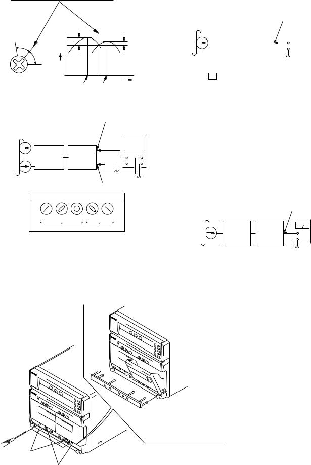
2.Turn the adjustment screw and check output peaks. If the peaks do not match for L-CH and R-CH, turn the adjustment screw so that outputs match within 1dB of peak.
L-CH |
within |
|
|
1dB |
|
|
|
peak |
|
|
within |
Output |
|
|
|
|
|
1dB |
|
level |
|
|
|
R-CH |
|
|
|
peak |
|
|
Screw |
Screw |
|
|
|
position |
L-CH |
R-CH |
position |
|
peak |
peak |
|
3. Mode: Playback
test tape |
AUDIO OUT (L) jack |
|||
P-4-A100 |
|
oscilloscope |
||
(10 kHz, –10 dB) |
|
|||
L-CH |
|
|
|
|
|
L-CH |
|
|
|
|
PFJ-1 |
V |
H |
|
set |
or |
|||
|
|
|||
STR-NX1/ |
|
|
||
|
|
|
||
|
NX3 |
|
|
|
R-CH |
R-CH |
|
|
|
|
|
|
||
|
AUDIO OUT (R) jack |
|||
waveform of oscilloscope |
|
|
||
in phase 45° |
90° 135° 180° |
|
|
|
good |
wrong |
|
|
|
4.Repeat step 1 to 3 in playback (REV) mode.
5.After the adjustments, apply suitable locking compound to the pats adjusted.
Adjustment Location: Playback Head (Deck A).
Record/Playback/Earth Head (Deck B).
Tape Speed Adjustment |
|
DECK B |
|
|
|
|
|
|
|
|
||||
• Execute only if connected to the STR-NX1/NX3 |
||||||||||||||
Mode: Playback |
|
|
|
|
|
|
|
|
|
|
|
|||
test tape |
|
|
AUDIO OUT jack |
|||||||||||
WS-48B |
|
|
||||||||||||
|
|
|
|
|
|
|
|
|
|
|
||||
(3 kHz, 0 dB) |
|
|
|
|
|
frequency counter |
||||||||
|
|
|
|
|
|
|
|
|
|
|
|
|
|
|
|
|
set |
|
STR-NX1/ |
|
|
|
|
|
|
|
|
|
|
|
|
|
|
|
|
|
|
|
|
|
|
|||
|
|
|
|
|
+ |
|
|
|||||||
|
|
|||||||||||||
|
|
|
|
|
|
|
|
|||||||
|
|
|
|
|
NX3 |
|
|
|
|
– |
|
|||
|
|
|
|
|
|
|
|
|
|
|
||||
|
|
|
|
|
|
|
|
|
|
|
|
|
|
|
|
|
|
|
|
|
|
|
|
|
|
|
|
|
|
|
|
|
|
|
|
|
|
|
|
|
|
|
|
|
1.Insert the WS-48B into the deck B.
2.Press the G (DECK B) button.
3.Press the [HI-DUB] button in playback mode. Then at HIGH speed mode.
4.Adjust RV1001 on the LEAF SW board do that frequency counter reads 6,000 ± 180 Hz.
5.Press the [HI-DUB] button.
Then back to NORMAL speed mode.
6.Adjust RV1002 on the LEAF SW board so that frequency counter reads 3,000 ± 90 Hz.
Adjustment Location: LEAF SW board
Sample value of Wow and Flutter: 0.3% or less W.RMS (JIS) (WS-48B)
Playback level Adjustment |
DECK A |
|
DECK B |
Procedure: |
|
|
|
Mode: Playback |
|
|
|
test tape |
AUDIO OUT jack |
||
P-4-L300 |
|||
(315 Hz, 0 dB) |
|
level meter |
|
|
PFJ-1 |
|
|
set |
or |
+ |
|
STR-NX1/ |
|||
|
– |
||
|
NX3 |
||
|
|
Deck A is RV311 (L-CH) and RV411 (R-CH), Deck B is RV301 (L-CH) and RV401 (R-CH) so that adjustment within specified value as follows.
Specified Value:
AUDIO OUT jack PB level: 301.5 to 338.3 mV (–8.2 to –7.2 dB) level
difference between the channels: within ± 0.5 dB
Adjustment Location: AUDIO board
Open the cassette holder and unhock six claws of the sub panel (TC2)
with tweezers or something,
then remove the sub panel (TC2).
forward
reverse
15
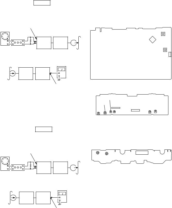
REC Bias Adjustment DECK B
Procedure:
1. Mode: Record
AUDIO IN jack
1) 315 Hz ü |
|
|
ý 50 mV (–23.8 dB) |
|
|
AF OSC 2) 10 kHz þ |
|
blank tape |
|
|
|
600 Ω |
|
CN-123 |
attenuator |
PFJ-1 |
|
|
or |
set |
|
STR-NX1/ |
|
|
|
|
|
NX3 |
|
2. |
Mode: Playback |
|
|
|
recorded |
|
level meter |
|
portion |
|
|
|
|
|
|
|
|
PFJ-1 |
|
|
set |
or |
+ |
|
STR-NX1/ |
||
|
|
– |
|
|
|
NX3 |
|
|
|
|
|
|
|
|
AUDIO OUT jack |
3.Confirm playback the signal recorded in step 1 become specified value as follows.
If these values are out of specified value, adjust the RV341 (L- CH) and RV441 (R-CH) on the AUDIO board to repeat steps 1and 2.
Specified value: Playback output of 315 Hz to playback output of 10 kHz: ± 0.5 dB
Adjustment Location: AUDIO board
REC Level Adjustment DECK B
Procedure:
1. Mode: Record
AUDIO IN jack |
|
|
315 Hz, 50 mV (–23.8 dB) |
|
|
AF OSC |
|
blank tape |
|
|
|
600 Ω |
|
CN-123 |
attenuator |
PFJ-1 |
|
|
or |
set |
|
STR-NX1/ |
|
|
|
|
|
NX3 |
|
2. |
Mode: Playback |
|
|
|
recorded |
|
level meter |
|
portion |
|
|
|
|
|
|
|
|
PFJ-1 |
|
|
set |
or |
+ |
|
STR-NX1/ |
||
|
|
– |
|
|
|
NX3 |
|
|
|
|
|
|
|
|
AUDIO OUT jack |
3.Confirm playback the signal recorded in step 1 become specified value as follows.
If these values are out of specified value, adjust the RV301 (L- CH) and RV351 (R-CH) on the MAIN board to repeat steps 1 and 2.
Specified value:
AUDIO OUT jack PB level: 47.2 to 53.0 mV (–24.3 to –23.3 dB)
Adjustment Location: MAIN board
– MAIN BOARD(Conductor Side) –
|
ü |
RV351 |
|
|
ï |
(R-CH) |
|
|
ï |
|
|
|
|
|
|
|
ï |
|
|
REC |
ý |
IC301 |
|
LEVEL ï |
|
|
|
|
ï |
RV301 |
|
|
ï |
|
|
|
þ |
(L-CH) |
1 |
|
|
|
|
|
|
CN301 |
|
|
|
|
3 |
– AUDIO BOARD(Component Side) –
|
RV441 |
|
|
|
|
RV401 |
IC602 |
|
|
|
|
|
|
CN601 |
|
RV411 |
|
RV301 |
|
RV311 |
|||
RV341 |
|
||||
|
|
|
|
|
|
L |
R |
R L |
|
L |
R |
ü ý þ |
ü ý þ |
|
ü ý þ |
||
PB LEVEL |
REC BIAS |
|
PB LEVEL |
||
– DECK B – |
|
– DECK A – |
|||
– LEAF SW BOARD(Component Side) – |
|
||||
TAPE SPEED |
|
|
|
||
þ ï ï ï ï ý ï ï ï ü |
|
|
|
||
(NORMAL) (HIGH) |
|
|
|
||
RV1002 |
RV1001 |
CN1001 |
|
||
16

CD SECTION
Note:
1.CD Block is basically designed to operate without adjustment. Therefore, check each item in order given.
2.Use YEDS-18 disc (3-702-101-01) unless otherwise indicated.
3.Use an oscilloscope with more than 10 MΩ impedance.
4.Clean the object lens by an applicator with neutral detergent when the signal level is low than specified value with the following checks.
5.Use the following extension cables and relay connector.
•Extension cable (19P) (Part No. J-2501-011-B)
Relay connector (Part No. J-2501-167-A) (BD board CN101 to MAIN board CN111)
• Extension cable (17P) (with connector) (Part No. J-2501-167-A) (CONNECTOR board CN701 to MAIN board CN301)
1. S-CURVE CHECK
oscilloscope
BD board
TP (FEO)  +
+
TP (VC) 
 –
–
Procedure:
1.Connect oscilloscope to TP (FEO).
2.Connect between TP (FEO) and TP (VC) by lead wire.
3.Connect between TP (AGCCON) and TP (GND) by lead wire.
4.Turn the power ON.
5.Load a disc (YEDS-18) and turn the power ON again and actuate the focus search. (Actuate the focus search when disc tray is moving in and out)
6.Check the oscilloscope waveform (S-curve) is symmetrical between A and B. And confirm peak to peak level within 2.4±0.7 Vp-p.
S-curve waveform
symmetry
A
within 2.4 ± 0.7 Vp-p
B
7. After check, remove the lead wire connected in step 2.
Note: • Try to measure several times to make sure than the ratio of A : B or B : A is more than 10 : 7.
• Take sweep time as long as possible and light up the brightness to obtain best waveform.
2.RF LEVEL CHECK
oscilloscope
BD board
TP (RF)  +
+
TP (VC) 
 –
–
Procedure:
1.Connect oscilloscope to TP (RF).
As TP (RF) and TP (VC) are located at the edge of board, clip them together with the board using alligator clips.
2.Turn the power ON.
3.Load a disc (YEDS-18) and playback.
4.Confirm that oscilloscope waveform is clear and check RF sig-
nal level is correct or not.
Note: Clear RF signal waveform means that the shape “  ” can be clearly distinguished at the center of the waveform.
RF signal waveform
VOLT/DIV: 200 mV
TIME/DIV: 500 ns
level:
1.2 ± 0.2 Vp-p
17
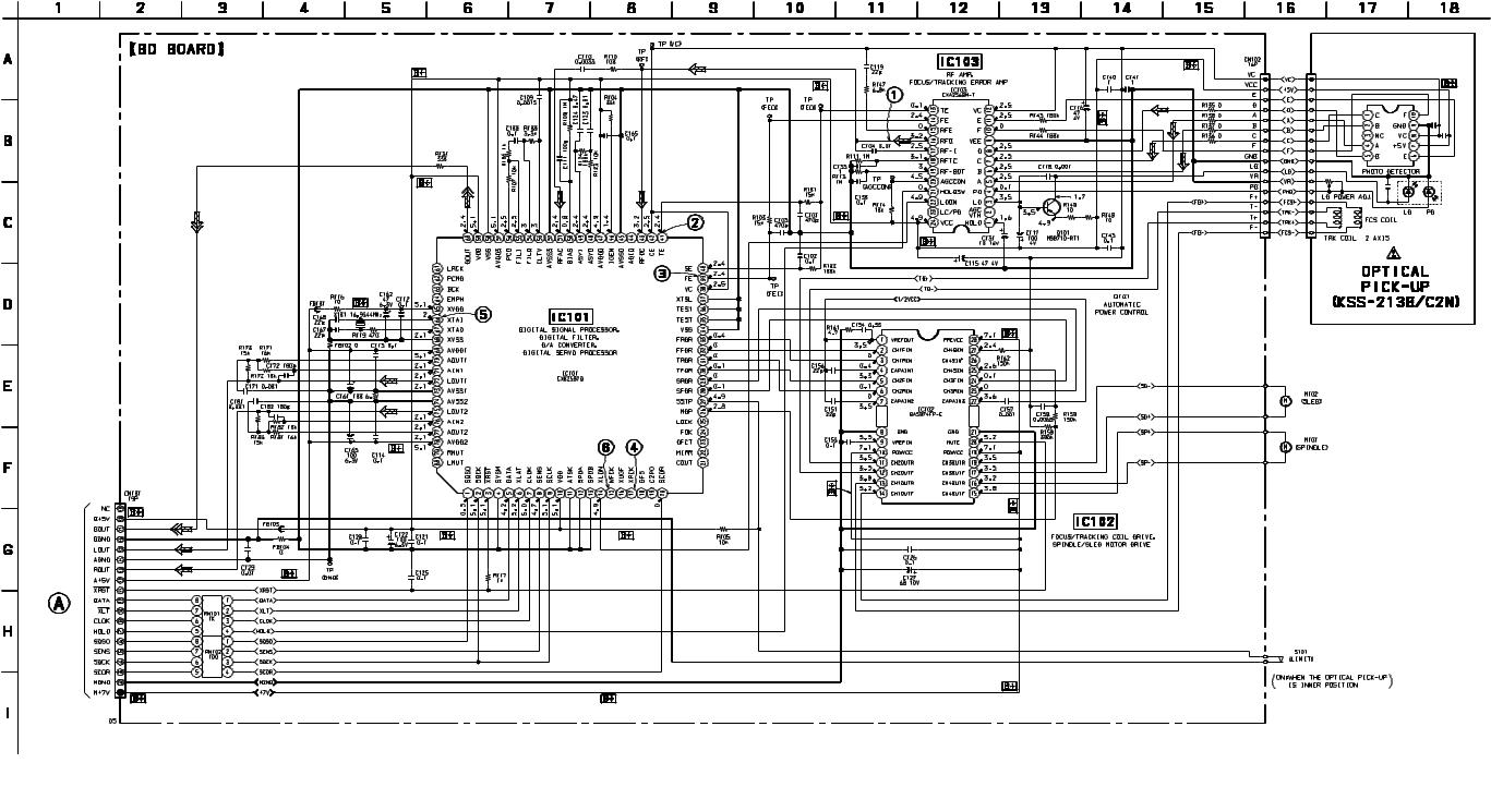
HTC-NX1
7-3. SCHEMATIC DIAGRAM – BD Board – See• page 32 for Waveforms. •See page 32 for IC Block Diagrams.
(Page 29)
• Voltages and waveforms are dc with respect to ground under no-signal conditions.
no mark : CD PLAY
The components identified by mark 0 or dotted |
Les composants identifiés par une marque 0 sont |
line with mark 0 are critical for safety. |
critiques pour la sécurité. Ne les remplacer que |
Replace only with part number specified. |
par une pièce portant le numéro spécifié. |
|
|
21 21
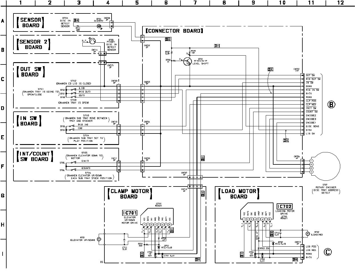
7-5. SCHEMATIC DIAGRAM – CD MOTOR/SENSOR Section – See• page 33 for IC Block Diagram.
HTC-NX1
•Voltages are dc with respect to ground under no-signal conditions.
no mark : CD PLAY
(Page 29)
(Page 29)
23 23
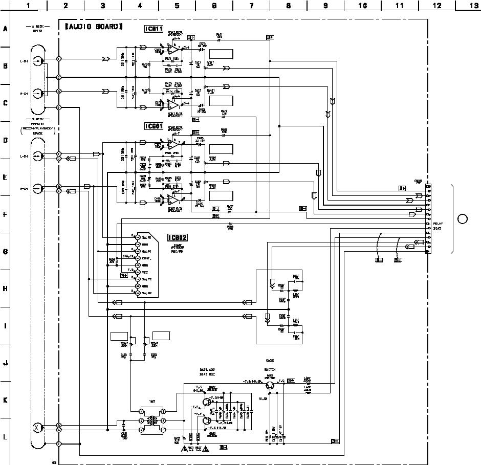
7-7. SCHEMATIC DIAGRAM – AUDIO Board – See• page 33 for IC Block Diagram.
(PLAYBACK) |
PB EQ AMP |
|
(DECK A) |
PB LEVEL (L)
(DECK A)
PB LEVEL (R)
(DECK A)
PB EQ AMP (DECK B)
PB LEVEL (L)
(DECK B)
PB LEVEL (R)
(DECK B)
SWITCHING
REC BIAS (R) |
REC BIAS (L) |
(DECK B) |
(DECK B) |
REC BIAS
-6.8
BIAS OSC
HTC-NX1
NC
A +7.5V
APB–LCH
APB–RCH
AGND
BPB–LCH
BPB–RCH
A –7.5V |
D (Page 28) |
|
|
–VBIAS (–7.5V) |
|
+VBIAS (+7.5V) |
|
B–REC–RCH |
|
B–REC–LCH |
|
TC–HEAD–GND |
|
•Voltages are dc with respect to ground under no-signal conditions.
no mark : TAPE PLAYBACK |
|
|
( |
) : RECORD |
|
|
|
|
The components identified by mark 0 or dotted |
Les composants identifiés par une marque 0 sont |
|
line with mark 0 are critical for safety. |
critiques pour la sécurité. Ne les remplacer que |
|
Replace only with part number specified. |
par une pièce portant le numéro spécifié. |
|
|
|
|
25 25
HTC-NX1
7-8. PRINTED WIRING BOARD – LEAF SW Board – See• page 19 for Circuit Boards Location.
|
|
DECK A |
( |
) |
DECK B |
|
|
PLUNGER |
|||
|
|
PLUNGER |
|
|
|
|
|
|
|
|
|
4 |
3 |
|
|
4 |
3 |
|
|
|
|
(DECK B PLAY) |
|
1 |
2 |
|
|
1 |
2 |
(DECK A PLAY) |
|
|
|
|
(DECK B 120/70) |
|
|
|
(DECK B HALF) |
|
|
|
|
|
|
|
|
05 |
(DECK A HALF) |
(DECK A 120/70) |
|
(DECK A REC) |
|
|
|
|
|
L (Page 27)
(DECK B REC)
21
21
7-9. SCHEMATIC DIAGRAM – LEAF SW Board –
CONTROL SWITCH
(CAPSTAN)
DECK B |
DECK A |
PLUNGER |
PLUNGER |
ROTATION DETECT SENSOR
(DECK A)
CAPM–
(DECK A 120/70) |
CAPM+ |
|
|
ROTATION DETECT |
CAPM–H/L |
|
SENSOR (DECK B) |
A–TRGM |
|
|
|
(DECK A HALF) |
|
TRGM–GND |
|
B–TRGM |
|
|
|
|
|
|
A–SHUT |
|
|
DGND |
(DECK A REC) |
|
A–HALF |
|
|
|
|
|
+5V |
(DECK B HALF) |
|
A–120/70 |
|
B–SHUT |
|
|
|
|
|
|
A PLAY |
(DECK B REC) |
|
B–HALF / REC–A / REC–B |
|
B–120/70 |
|
|
|
|
|
|
B PALY |
(DECK B 120/70) |
|
NC |
|
|
|
(DECK A PLAY) |
(DECK B PLAY) |
|
E (Page 28)
•Voltages are dc with respect to ground under no-signal conditions.
no mark : TAPE PLAYBACK ( ) : RECORD
: Impossible to measure
26 26
HTC-NX1
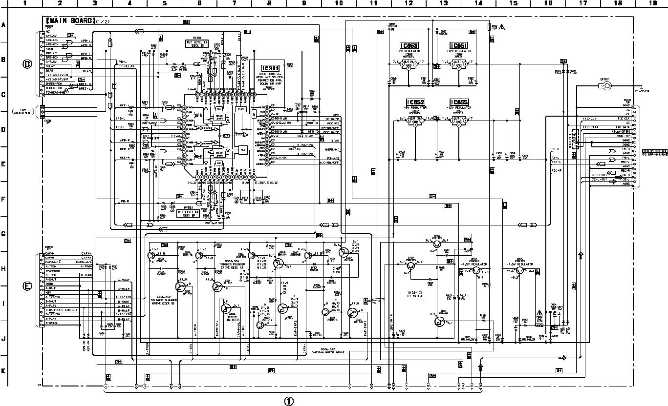
7-11. SCHEMATIC DIAGRAM – MAIN Board (1/2) –
(Page 25)
(Page 26)
• Voltages are dc with respect to ground under no-signal conditions.
no mark : CD PLAY
( |
) : TAPE PLAYBACK (DECK A) |
[ |
] : TAPE PLAYBACK (DECK B) |
ááññ : RECORD
(Page 29)
The components identified by mark 0 or dotted |
Les composants identifiés par une marque 0 sont |
line with mark 0 are critical for safety. |
critiques pour la sécurité. Ne les remplacer que |
Replace only with part number specified. |
par une pièce portant le numéro spécifié. |
|
|
28 28

HTC-NX1
7-12. SCHEMATIC DIAGRAM – MAIN Board (2/2) – See• page 32 for Waveform.
(Page 28)
(Page 23) |
(Page 31) |
|
(Page 23)
(Page 31)
(Page 31)
(Page 21)
|
|
|
|
|
• Voltages and waveforms are dc with respect to ground |
[ |
] : TAPE PLAYBACK (DECK B) |
||
under no-signal conditions. |
áá |
ññ : RECORD |
||
no mark : CD PLAY |
|
: Impossible to measure |
||
( |
) : TAPE PLAYBACK (DECK A) |
|
|
|
29 29
HTC-NX1
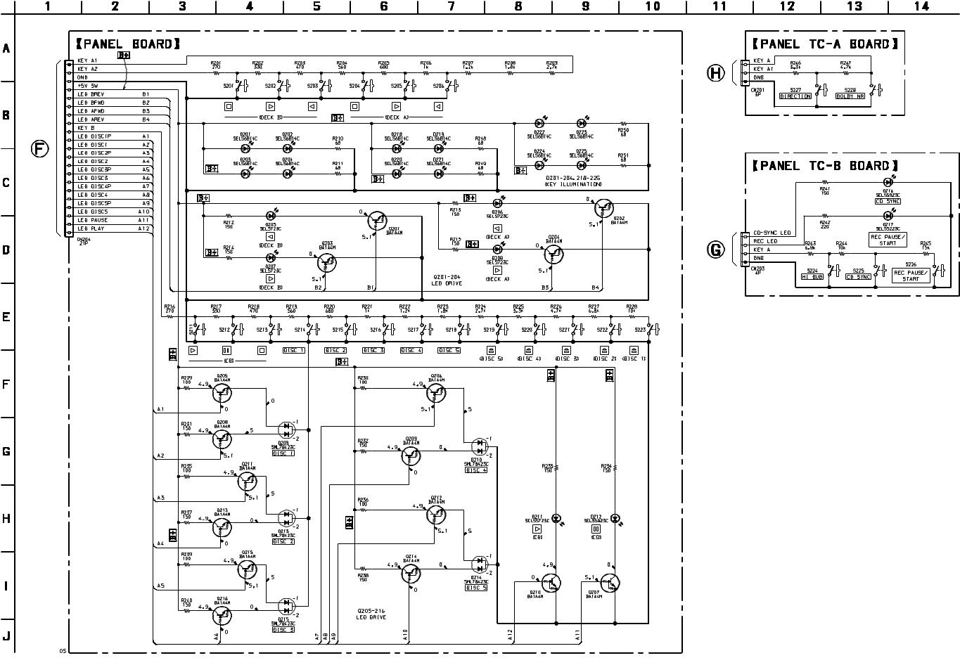
7-14. SCHEMATIC DIAGRAM – PANEL Section –
(Page 29)
(Page 29)
(Page 29)
• Voltages are dc with respect to ground under no-signal conditions.
no mark : CD PLAY
31 31
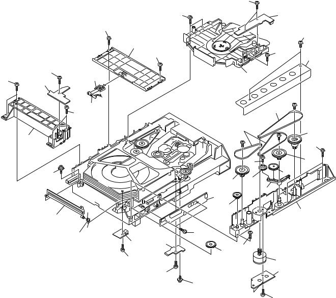
(3)CD MECHANISM DECK SECTION-1 (CDM53D-K1BD33)
|
|
|
|
|
151 |
|
|
|
|
|
151 |
|
164 |
|
|
|
151 |
|
|
151 |
|
|
|
|
|
|
|
|
|
|
177 |
|
|
|
|
|
|
|
151 |
|
151 |
|
|
|
|
|
|
166 |
|
151 |
162 |
|
|
165 |
|
151 |
160 |
|
|
|
||
|
|
|
|
|
|
|
|
|
161 |
|
|
|
#3 |
|
|
|
|
|
167 |
|
|
|
151 |
|
|
|
|
|
|
|
|
|
|
|
|
|
|
|
|
168 |
169 |
|
159 |
|
|
|
#3 |
|
|
|
|
|
#3 |
||
|
|
|
|
|
||
|
|
|
|
|
|
151 |
|
|
|
|
|
151 |
170 |
|
|
|
|
|
|
|
|
158 |
|
|
|
|
171 |
|
|
|
170 |
173 |
|
|
|
|
|
|
172 |
||
|
|
|
|
174 |
|
|
|
|
|
|
|
|
|
|
|
|
|
171 |
|
176 |
|
157 |
|
|
|
|
|
|
|
|
|
|
|
|
|
|
156 |
|
151 |
|
|
|
|
|
154 |
|
|
|
|
|
|
155 |
151 |
|
|
|
|
|
153 |
|
||
|
|
|
151 |
|
||
|
|
|
|
|
M702 |
|
|
|
|
|
|
|
|
|
|
|
|
151 |
|
152 |
|
|
|
|
|
|
|
|
|
|
|
175 |
|
|
|
|
|
|
|
|
151 |
Ref. No. |
Part No. |
Description |
Remark |
Ref. No. |
Part No. |
Description |
Remark |
|
|
151 |
4-218-253-01 |
SCREW (M2.6), +BVTP |
|
166 |
4-214-129-01 COVER |
|
|
* |
152 |
1-671-508-21 |
LOAD MOTOR BOARD |
|
167 |
4-211-235-01 |
BELT (COMMUNICATION) |
|
|
153 |
4-220-261-01 |
GEAR (EJECT) |
|
168 |
4-211-236-01 |
BELT (LOADING) |
|
* |
154 |
1-671-502-21 |
INT/COUNT SW BOARD |
|
169 |
4-220-278-01 |
PULLEY (MODE) |
|
* |
155 |
1-671-504-21 |
SENSOR BOARD |
|
170 |
4-220-276-01 |
PULLEY (LD) |
|
|
156 |
4-212-676-03 |
SPRING (LID), TORSION |
|
171 |
4-220-267-01 |
GEAR (LD DECELERATION) |
|
|
157 |
4-220-285-01 |
LID (DISC) |
|
172 |
4-220-272-01 |
LEVER (GOOSENECK) |
|
|
158 |
4-985-672-01 |
SCREW (+PTPWH M2.6), FLOATING |
|
173 |
4-220-271-01 |
GEAR (TRAY) |
|
|
159 |
A-4672-622-F |
BASE (GUIDE) ASSY, FITTING |
|
* 174 |
1-671-506-21 |
CONNECTOR BOARD |
|
* |
160 |
1-671-503-21 |
OUT SW BOARD |
|
175 |
3-341-549-21 SCREW (2.6X12) (DIA. 7.5), +PTP WH |
|
|
* |
161 |
1-671-789-21 |
SENSOR 2 BOARD |
|
176 |
4-213-488-04 |
CHASSIS (MOLD B) |
|
|
162 |
4-220-274-01 |
HOLDER (SENSOR) |
|
177 |
4-213-579-01 |
BRACKET (CHASSIS) |
|
* |
164 |
1-671-505-21 |
IN SW BOARD |
|
M702 |
X-4950-342-1 |
MOTOR (LOADING) ASSY |
|
|
165 |
A-4680-437-A |
MAGNET ASSY |
|
|
|
|
|
39
 Loading...