


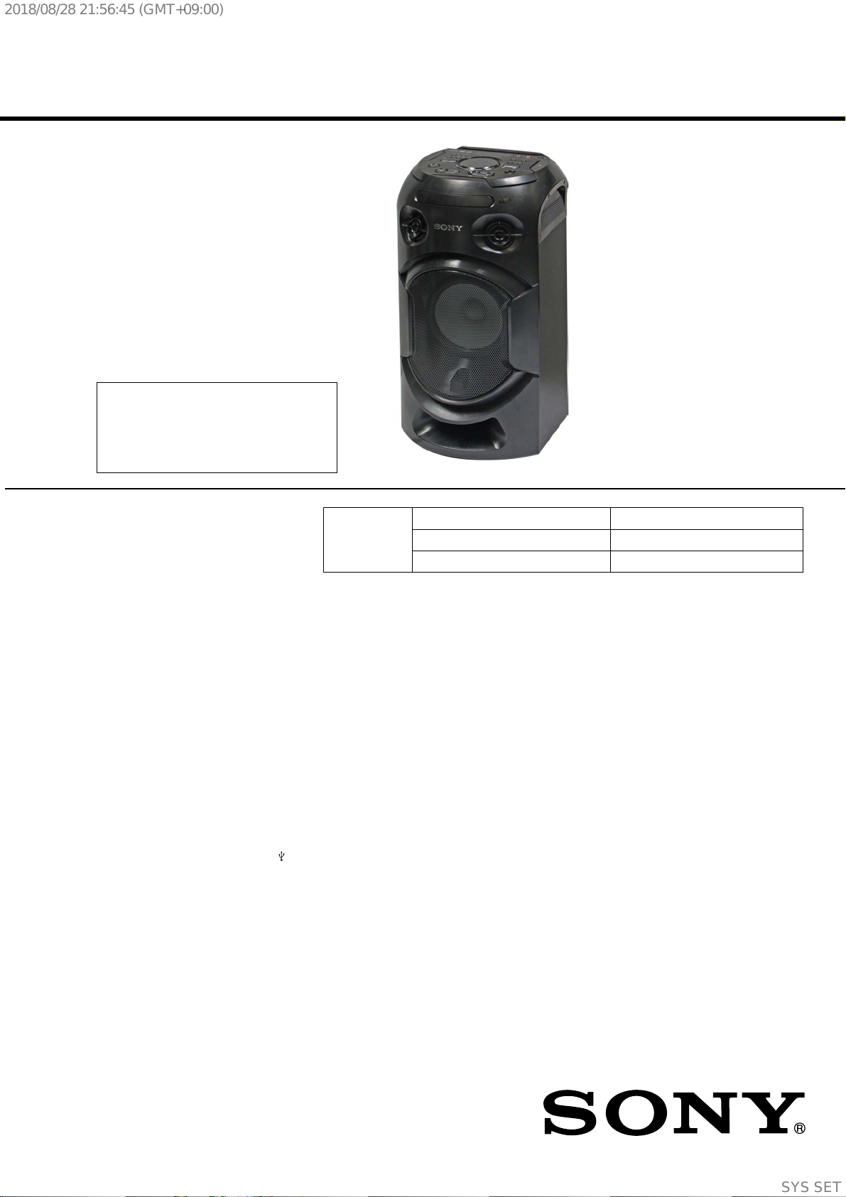
MHC-V21
SERVICE MANUAL
Sony Corporation
Published by Sony EMCS (Malaysia) PG Tec
US Model
Canadian Model
MHC-V21
AEP Model
UK Model
E Model
Australian Model
MHC-V21D
MHC-V21/V21D
HOME AUDIO SYSTEM
9-890-697-02
2018H80-1
©
2018.08
Ver. 1.1 2018.08
SPECIFICATIONS
CD/DVD Section
Model Name Using Similar Mechanism MHC-V71D
CD/DVD Mechanism Type CDM90-DVBU204//M
Optical Pick-up Name CMS-S76RFS7G1 or CMS-S76RFS7GP
Note:
Be sure to keep your PC used for service and
checking of this unit always updated with the
latest version of your anti-virus software.
In case a virus aff ected unit was found during
service, contact your Service Headquarters.
– Continued on next page –
AUDIO POWER SPECIFICATIONS
POWER OUTPUT AND TOTAL HARMONIC
DISTORTION:
(US models only)
With 3 ohm loads, both channels driven, from
800 Hz – 20,000 Hz; rated 30 watts per channel
minimum RMS power at stereo mode, with no
more than 0.7% total harmonic distortion from
250 milliwatts to rated output.
Speaker section
Speaker system:
2-way, Bass Reflex
Speaker unit:
Tweeter L/R: 66 mm (2 5/8 in),
cone type
Woofer: 200 mm (8 in), cone type
Inputs
AUDIO/PARTY CHAIN IN L/R (V21):
Voltage 2 V, impedance
47 kilohms
AUDIO/PARTY CHAIN IN (TV) L/R (V21D):
Voltage 2 V, impedance
47 kilohms
TV (ARC) (V21D):
Supported audio signal:
2-channel Linear PCM
MIC1:
Sensitivity 1 mV, impedance
10 kilohms
MIC2/GUITAR:
Sensitivity 1 mV, impedance
10 kilohms (When guitar mode is
turned off .)
Sensitivity 200 mV, impedance
250 kilohms (When guitar mode is
turned on.)
Outputs
AUDIO/PARTY CHAIN OUT L/R:
Voltage 2 V, impedance 1 kilohm
VIDEO OUT (V21D):
Max. output level 1 Vp-p, unbalanced,
Sync. negative load impedance 75 ohms
HDMI OUT (TV) ARC (V21D):
Supported audio signal:
2-channel Linear PCM (up to 48 kHz),
Dolby Digital
HDMI section (V21D)
Connector:
Type A (19 pin)
Disc player section
System:
Compact disc and digital audio and
video system
Laser Diode Properties
Emission Duration: Continuous
Laser Output*: Less than 44.6 μW
* This output is the value measure-
ment at a distance of 200 mm
from the objective lens surface on
the Optical Pick-up Block with
7 mm aperture.
Frequency response:
20 Hz – 20 kHz
Video color system format (V21D):
Latin American model:
NTSC
Other models:
NTSC and PAL
USB section
Supported USB device:
Mass Storage Class
Maximum current:
1 A
(USB) port:
Type A
FM tuner section
FM stereo, FM superheterodyne tuner
Antenna:
FM lead antenna
Tuning range:
87.5 MHz – 108.0 MHz (100 kHz step)
(V21)
87.5 MHz – 108.0 MHz (50 kHz step)
(V21D)
BLUETOOTH section
Communication system:
BLUETOOTH Standard version 4.2
Output:
BLUETOOTH Standard Power
Class 2
Maximum output power (V21D):
< 9.5 dBm
Maximum number of devices to be
registered:
8 devices
Maximum number of simultaneous
connection (Multipoint):
3 devices
Maximum communication range:
Line of sight approx. 10 m (33 ft)
1)
Frequency band:
2.4 GHz band (2.4000 GHz –
2.4835 GHz)
Modulation method:
FHSS (Freq Hopping Spread
Spectrum)
Compatible BLUETOOTH profiles
2)
:
A2DP (Advanced Audio
Distribution Profile)
AVRCP (Audio Video Remote
Control Profile)
SPP (Serial Port Profile)
Supported codecs:
SBC (Subband Codec)
AAC (Advanced Audio Coding)
LDAC
1)
The actual range will vary depending on
factors such as obstacles between devices,
magnetic fields around a microwave oven,
static electricity, reception sensitivity,
antenna’s performance, operating system,
software application, etc.
2)
BLUETOOTH standard profiles indicate
the purpose of BLUETOOTH communica-
tion between devices.
NFC section
Operating frequency:
13.56 MHz
Supported audio formats
Supported bit rate and sampling frequencies:
MP3:
32/44.1/48 kHz, 32 kbps –
320 kbps (VBR)
AAC:
44.1 kHz, 48 kbps – 320 kbps
(CBR/VBR)
WMA:
44.1 kHz, 48 kbps – 192 kbps
(CBR/VBR)
WAV:
44.1/48 kHz (16 bit)
Supported video formats (V21D)
Xvid:
Video codec: Xvid video
Bit rate: 4.854 Mbps (MAX)
Resolution/Frame rate:
720 × 480, 30 fps
720 × 576, 25 fps (except for Latin
American model)
Audio codec: MP3
MPEG4:
File format: MP4 File Format
Video codec: MPEG4 Simple
Profi le (AVC is not compatible.)
Bit rate: 4 Mbps
Resolution/Frame rate:
720 × 480, 30 fps
720 × 576, 25 fps (except for Latin
American model)
Audio codec: AAC-LC (HE-AAC is
not compatible.)
DRM: Not compatible
General
Power requirements:
US, CND models:
AC 120 V, 60 Hz
Except US, CND models:
AC 120 V – 240 V, 50/60 Hz
Power consumption:
70 W
Power consumption (at the Power Saving
mode) (V21D):
0.5 W (When “BT STBY” is set to
“OFF” and [CONTROL FOR
HDMI] is set to [OFF].)
2 W* (When “BT STBY” is set to
“ON” and [CONTROL FOR HDMI]
is set to [ON].)
Dimensions (W/H/D) (Approx.):
324 mm × 600 mm × 286 mm
(12 7/8 in × 23 3/4 in × 11 3/8 in)
Mass (Approx.):
8.4 kg (18 lb)
Operating temperature:
5 °C to 35 °C (41 °F to 95 °F)
Photo: MHC-V21D
SYSSET
2018/08/2821:56:45(GMT+09:00)

MHC-V21/V21D
2
SAFETY-RELATED COMPONENT WARNING!
COMPONENTS IDENTIFIED BY MARK 0 OR DOTTED LINE
WITH MARK 0 ON THE SCHEMATIC DIAGRAMS AND IN
THE PARTS LIST ARE CRITICAL TO SAFE OPERATION.
REPLACE THESE COMPONENTS WITH SONY PARTS
WHOSE PART NUMBERS APPEAR AS SHOWN IN THIS
MANUAL OR IN SUPPLEMENTS PUBLISHED BY SONY.
ATTENTION AU COMPOSANT AYANT RAPPORT
À LA SÉCURITÉ!
LES COMPOSANTS IDENTIFIÉS PAR UNE MARQUE 0 SUR
LES DIAGRAMMES SCHÉMATIQUES ET LA LISTE DES
PIÈCES SONT CRITIQUES POUR LA SÉCURITÉ DE FONC-
TIONNEMENT. NE REMPLACER CES COMPOSANTS QUE
PAR DES PIÈCES SONY DONT LES NUMÉROS SONT DON-
NÉS DANS CE MANUEL OU DANS LES SUPPLÉMENTS
PUBLIÉS PAR SONY.
1.5 kΩ0.15 μF
AC
voltmeter
(0.75 V)
To Exposed Metal
Parts on Set
Earth Ground
Fig. A. Using an AC voltmeter to check AC leakage.
NOTES ON CHIP COMPONENT REPLACEMENT
• Never reuse a disconnected chip component.
• Notice that the minus side of a tantalum capacitor may be
damaged by heat.
FLEXIBLE CIRCUIT BOARD REPAIRING
• Keep the temperature of the soldering iron around 270 °C
during repairing.
• Do not touch the soldering iron on the same conductor of the
circuit board (within 3 times).
• Be careful not to apply force on the conductor when soldering
or unsoldering.
SAFETY CHECK-OUT
After correcting the original service problem, perform the following
safety check before releasing the set to the customer:
Check the antenna terminals, metal trim, “metallized” knobs,
screws, and all other exposed metal parts for AC leakage. Check
leakage as described below.
LEAKAGE TEST
The AC leakage from any exposed metal part to earth ground and
from all exposed metal parts to any exposed metal part having a
return to chassis, must not exceed 0.5 mA (500 microamperes).
Leakage current can be measured by any one of three methods.
1. A commercial leakage tester, such as the Simpson 229 or RCA
WT-540A. Follow the manufacturers’ instructions to use these
instruments.
2. A battery-operated AC milliammeter. The Data Precision 245
digital multimeter is suitable for this job.
3. Measuring the voltage drop across a resistor by means of a
VOM or battery-operated AC voltmeter. The “limit” indication
is 0.75 V, so analog meters must have an accurate low-voltage
scale. The Simpson 250 and Sanwa SH-63Trd are examples
of a passive VOM that is suitable. Nearly all battery operated
digital multimeters that have a 2V AC range are suitable. (See
Fig. A)
Ver. 1.1
* The power consumption of the system will be less than 0.5 W when
there is no HDMI connection and “BT STBY” is set to “OFF”.
Design and specifications are subject to change without notice.
Unpacking
• This unit (MHC-V21/V21D) (1)
• Remote control (1)
• R03 (size AAA) batteries (2)
• FM lead antenna (1)
• AC power cord (mains lead) (1)
• AC plug adaptor* (1) (supplied only for certain areas) (V21D)
* This plug adaptor is not for the use in Chile, Paraguay and
Uruguay. Use this plug adaptor in the countries where it is
necessary.
License and Trademark Notice
• “CD” logo is trademark.
•
is a trademark of DVD Format/Logo Licensing Corporation.
• “DVD+RW”, “DVD-RW”, “DVD+R”, “DVD-R”, “DVD VIDEO”,
and the “CD” logos are trademarks.
• WALKMAN
®
and WALKMAN
®
logo are registered trademarks
of Sony Corporation.
• MPEG Layer-3 audio coding technology and patents licensed from
Fraunhofer IIS and Thomson.
• Windows Media is either a registered trademark or trademark
of Microsoft Corporation in the United States and/or other
countries.
• This product is protected by certain intellectual property rights
of Microsoft Corporation. Use or distribution of such technology
outside of this product is prohibited without a license from
Microsoft or an authorized Microsoft subsidiary.
• This system incorporates Dolby* Digital.
* Manufactured under license from Dolby Laboratories. Dolby,
Dolby Audio, and the double-D symbol are trademarks of Dolby
Laboratories.
• This system incorporates High-Definition Multimedia Interface
(HDMI™) technology. The terms HDMI and HDMI High-
Definition Multimedia Interface, and the HDMI Logo are
trademarks or registered trademarks of HDMI Licensing
Administrator, Inc. in the United States and other countries.
• “BRAVIA” is a trademark of Sony Corporation.
• LDAC™ and LDAC logo are trademarks of Sony Corporation.
• The BLUETOOTH
®
word mark and logos are registered trade-
marks owned by the Bluetooth SIG, Inc. and any use of such
marks by Sony Corporation is under license. Other trademarks
and trade names are those of their respective owners.
• The N-Mark is a trademark or registered trademark of NFC
Forum, Inc. in the United States and in other countries.
• Android is a trademark of Google LLC.
• Google Play and the Google Play logo are trademarks of Google
LLC.
• Apple, iPhone, and iPod touch are trademarks of Apple Inc.,
registered in the U.S. and other countries. App Store is a service
mark of Apple Inc., registered in the U.S. and other countries.
• Use of the Made for Apple badge means that an accessory has
been designed to connect specifically to the Apple product(s)
identified in the badge, and has been certified by the developer
to meet Apple performance standards. Apple is not responsible
for the operation of this device or its compliance with safety and
regulatory standards.
• THIS PRODUCT IS LICENSED UNDER THE MPEG-4 VISUAL
PATENT PORTFOLIO LICENSE FOR THE PERSONAL AND
NON-COMMERCIAL USE OF A CONSUMER FOR
(i) ENCODING VIDEO IN COMPLIANCE WITH THE MPEG-4
VISUAL STANDARD (“MPEG-4 VIDEO”)
AND/OR
(ii) DECODING MPEG-4 VIDEO THAT WAS ENCODED BY
A CONSUMER ENGAGED IN A PERSONAL AND NON-
COMMERCIAL ACTIVITY AND/OR WAS OBTAINED FROM
A VIDEO PROVIDER LICENSED TO PROVIDE MPEG-4
VIDEO.
NO LICENSE IS GRANTED OR SHALL BE IMPLIED FOR ANY
OTHER USE. ADDITIONAL INFORMATION INCLUDING THAT
RELATING TO PROMOTIONAL, INTERNAL AND COMMER-
CIAL USES AND LICENSING MAY BE OBTAINED FROM MPEG
LA, L.L.C.
HTTP://WWW.MPEGLA.COM
• All other trademarks are trademarks of their respective owners.
• In this manual, ™ and
®
marks are not specified.
SYSSET
2018/08/2821:56:45(GMT+09:00)
MHC-V21/V21D
3
1. SERVICING NOTES ............................................. 4
2. DISASSEMBLY
2-1. Disassembly Flow ........................................................... 10
2-2. Side Panel L, R ............................................................... 11
2-3. Top Panel Section ........................................................... 12
2-4. Loading Panel Assy ........................................................ 13
2-5. CDM Section .................................................................. 14
2-6. CDM90-DVBU204//M ................................................... 15
2-7. Service, Optical Device (7G), Flexible Flat Cable ......... 16
2-8. Back Panel ...................................................................... 17
2-9. MOTHERBOARD Board ............................................... 18
2-10. SMPS Board, Chassis Section ........................................ 19
2-11. Front Panel Section ......................................................... 20
2-12. Loudspeaker (20CM) (Woofer) (SP3) ............................ 21
3. TEST MODE ............................................................ 22
4. ELECTRICAL CHECK ......................................... 23
5. TROUBLESHOOTING .......................................... 24
6. DIAGRAMS
6-1. Block Diagram
- RS SERVO, USB, HDMI Section - .............................. 31
6-2. Block Diagram - MAIN Section - ................................... 32
6-3. Block Diagram - AMP Section - ..................................... 33
6-4. Block Diagram
- PANEL, POWER SUPPLY Section - ........................... 34
6-5. Block Diagram - SMPS Section - ................................... 35
6-6. Printed Wiring Board - MOTHERBOARD Board
(Component Side) - ......................................................... 37
6-7. Printed Wiring Board - MOTHERBOARD Board
(Conductor Side) - .......................................................... 38
6-8. Printed Wiring Board - PANEL Board - ......................... 39
6-9. Schematic Diagram - PANEL Board - ............................ 40
6-10. Printed Wiring Board - SMPS Board - ........................... 41
6-11. Printed Wiring Board - MIC USB Board - ..................... 42
6-12. Schematic Diagram - MIC USB Board - ........................ 43
6-13. Printed Wiring Board - IR Board - .................................. 44
6-14. Schematic Diagram - IR Board - .................................... 44
6-15. Printed Wiring Board - SPK LED Board - ..................... 44
6-16. Schematic Diagram - SPK LED Board - ........................ 44
6-17. Printed Wiring Board - NFC Board - .............................. 45
TABLE OF CONTENTS
7. EXPLODED VIEWS
7-1. Side Panel Section .......................................................... 46
7-2. Panel Loading Section .................................................... 47
7-3. MOTHERBOARD Board Section .................................. 48
7-4. Chassis Section ............................................................... 49
7-5. Front Panel Section ......................................................... 50
7-6. Speaker Cabinet Section ................................................. 51
7-7. Top Panel Section ........................................................... 52
7-8. CDM Section .................................................................. 53
7-9. DVD Mechanism Section
(CDM90-DVBU204//M) ................................................ 54
8. ELECTRICAL PARTS LIST .............................. 55
Accessories are listed in the last part of the electrical parts list.
Ver. 1.1
SYSSET
2018/08/2821:56:45(GMT+09:00)

MHC-V21/V21D
4
SECTION 1
SERVICING NOTES
UNLEADED SOLDER
Boards requiring use of unleaded solder are printed with the
leadfree mark (LF) indicating the solder contains no lead.
(Caution: Some printed circuit boards may not come printed with
the lead free mark due to their particular size)
: LEAD FREE MARK
Unleaded solder has the following characteristics.
• Unleaded solder melts at a temperature about 40 °C higher
than ordinary solder.
Ordinary soldering irons can be used but the iron tip has to be
applied to the solder joint for a slightly longer time.
Soldering irons using a temperature regulator should be set to
about 350 °C.
Caution: The printed pattern (copper foil) may peel away if
the heated tip is applied for too long, so be careful!
• Strong viscosity
Unleaded solder is more viscous (sticky, less prone to fl ow)
than ordinary solder so use caution not to let solder bridges
occur such as on IC pins, etc.
• Usable with ordinary solder
It is best to use only unleaded solder but unleaded solder may
also be added to ordinary solder.
CAUTION
Use of controls or adjustments or performance of procedures
other than those specifi ed herein may result in hazardous radiation
exposure.
NOTES ON HANDLING THE OPTICAL PICK-UP BLOCK
OR BASE UNIT
The laser diode in the optical pick-up block may suff er electrostatic
break-down because of the potential diff erence generated by the
charged electrostatic load, etc. on clothing and the human body.
During repair, pay attention to electrostatic break-down and also
use the procedure in the printed matter which is included in the
repair parts.
The fl exible board is easily damaged and should be handled with
care.
NOTES ON LASER DIODE EMISSION CHECK
The laser beam on this model is concentrated so as to be focused
on the disc refl ective surface by the objective lens in the optical
pickup block. Therefore, when checking the laser diode emission,
observe from more than 30 cm away from the objective lens.
For customers in AEP, UK
This appliance is classifi ed as a
CLASS 1 LASER product under
IEC 60825-1:2007. This marking
is located on the rear exterior.
For customers in EA
This appliance is classifi ed as a
CLASS 1 LASER product under
IEC 60825-1:2007. This marking
is located on the rear exterior.
MODEL IDENTIFICATION
– Rear View –
R
MODEL NUMBER LABEL
AEP, UK, RU, AR, AUS, E12, EA, E4, LA9, MY
MODEL NO. / MODELO :
MHC-V21D
R
US, CND, TH, BR
MODEL NO. :
MHC-V21D
Destination Code
PAR T N o .
Destination Code
PART No.
Ver. 1.1
SYSSET
2018/08/2821:56:45(GMT+09:00)
MHC-V21/V21D
5
Model Part No.
V21D : LA9
4-734-059-0[]
V21D : AR
4-734-059-1[]
V21D : E4
4-734-059-2[]
V21D : EA
4-734-059-3[]
V21D : E12
4-734-059-4[]
V21D : MY
4-734-059-5[]
V21D : AUS
4-734-059-6[]
V21D : TH
4-734-059-7[]
V21D : AEP, UK
4-734-059-8[]
V21D : RU
4-734-059-9[]
V21 : US, CND
4-734-060-0[]
V21D : BR
4-734-060-1[]
DESTINATION ABBREVIATIONS
The following abbreviations for model destinations are used in this
service manual.
• Abbreviation
AR : Argentina model
AUS : Australian model
BR : Brazilian model
CND : Canadian model
E4 : African model
E12 : 220-240 V AC area in E model
EA3 : Saudi Arabia model
LA9 : Latin-American model
MY : Malaysia model
RU : Russian model
TH : Thai model
DESTINATION SETTING METHOD
The destination information isn’t written in the MOTHERBOARD
board for the service.
Therefore, when the MOTHERBOARD board is replaced, be sure
to perform the destination setting (Important work).
Note 1: The initial setting destination of the MOTHERBOARD board for
the service is temporary set as “LATIN”. The message “LATIN
(T)” is displayed on the screen display panel.
Note 2: When distinguishing the destination of the product, refer to the
“MODEL IDENTIFICATION” on page 4.
Note 3: If destination setting isn’t performed, it is possibility to occur the
defect to each operation of this unit.
Note 4: Destination would be locked if it has been changed for 5 times.
Procedure:
1. Press two buttons of the [VOICE CHANGER] and
[TUNING + >] simultaneously for 10 seconds during the
demo mode.
2. It enters the destination setting mode, the message
“D XXXXX” is displayed on the screen display panel.
Note 5: If the message “DESTLOCK” is displayed on the screen display
panel, press the [N] button to release from this mode. Because
the destination is locked, and it cannot change the destination.
3. Press [ +] / [ ―] button to select the destination based on the
set’s country.
Screen
display
Destination
code
Country
“D ASIA
” SP6, TH1 Southeast Asia countries
“D INDIA
” E12 India
“D ME AFC” E3, E93, E4,
SA2, EA3
Middle East & Africa countries
“D OCEANI” AU1 Australia & New Zealand
“D JAPAN” J1 Japan
“D BRAZIL
” BR1 Brazil
“D N AME” UC2, CA2 America & Canada
“D LATIN
” LA9, AR2 Central & South America
countries (except Brazil)
“D RUSSIA
” RU1 Russia & CIS countries
“D EUROPE” CEL, CEK Europe countries
(except CIS country)
4. Press [
N] button to confi rm the selection.
5. “RESET” appears on the screen display panel. After that,
“SONY” appears on the screen display panel. The system
automatically turn on and off once. Please be sure that the
system stay at demo mode fi nally before switch off the power
supply.
6. Mode in “MODEL, DESTINATION AND VERSION
DISPLAY MODE” on page 21 again to confi rm on the model
& destination.
PLAYABLE DISCS
• DVD VIDEO
• DVD-R/DVD-RW in DVD VIDEO format or video mode
• DVD+R/DVD+RW in DVD VIDEO format
• VIDEO CD (Ver. 1.0, 1.1, and 2.0 discs)
• Super VCD
• CD-R/CD-RW/CD-ROM in VIDEO CD format or super VCD
format
• AUDIO CD
• CD-R/CD-RW in AUDIO CD format
PLAYABLE FILES ON DISCS
• Music: MP3 fi les
(.mp3)
1)2)
• Video: MPEG4 fi les (.mp4/.m4v)
2)3)
, Xvid fi les (.avi)
PLAYABLE FILES ON USB DEVICE
• Music: MP3 fi les
(.mp3)
1)2)
, WMA fi les (.wma)
2)
, AAC fi les
(.m4a/.mp4/.3gp)
2)
, WAV fi les (.wav)
2)
• Video: MPEG4 fi les (.mp4/.m4v)
2)3)
, Xvid fi les (.avi)
1)
MP3 (MPEG 1 Audio Layer 3) is a standard format defi ned by
ISO/MPEG for compressed audio data. MP3 fi les must be in
MPEG 1 Audio Layer 3 format.
2)
Files with copyright protection (Digital Rights Management)
cannot be played back by the system.
3)
MPEG4 fi les must be recorded in MP4 fi le format. Supported
video codec and audio codec are as follows:
– Video codec: MPEG4 Simple Profi le (AVC is not supported.)
– Audio codec: AAC-LC (HE-AAC is not supported.)
Ver. 1.1
SYSSET
2018/08/2821:56:45(GMT+09:00)
MHC-V21/V21D
6
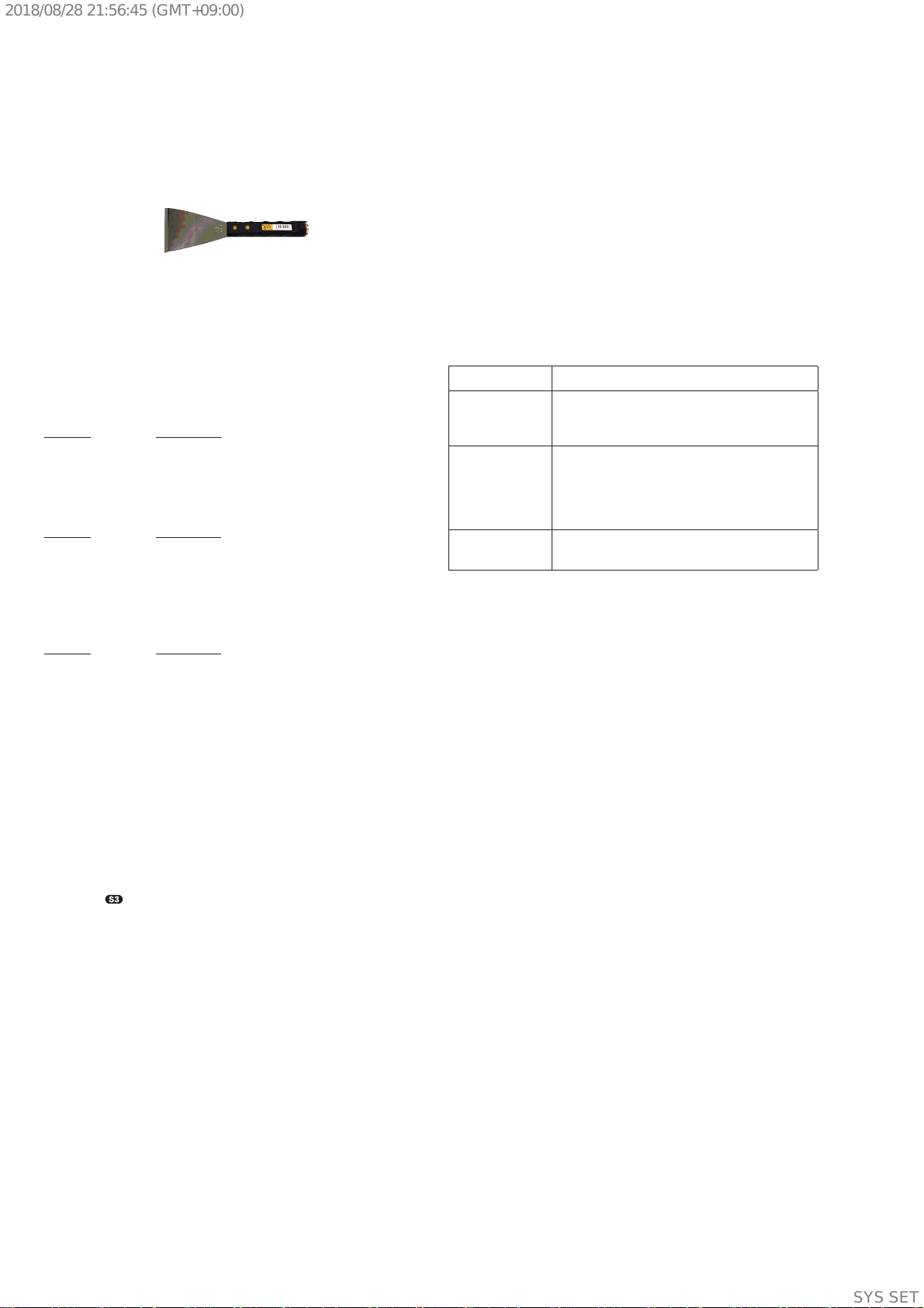
Note
• JIG
When disassembling the set, use the following jig (for front
panel removal).
Part No.: J-2501-238-A JIG FOR SPEAKER REMOVAL
NOTE OF REPLACEMENT OF THE MS-476 BOARD
When the MS-476 board is defective, exchange the entire
LOADING COMPLETE ASSY (T).
TEST DISCS
Use following TEST DISC when this unit confi rms the operation
and checks it.
• For CD
Part No. Description
3-702-101-01 DISC (YEDS-18), TEST
4-225-203-01 DISC (PATD-012), TEST
J-2501-307-A DISC (HLX-A1), TEST
• For DVD SL (Single Layer)
Part No. Description
J-6090-069-A DISC (HLX-503), TEST (NTSC)
J-6090-088-A DISC (HLX-504), TEST (NTSC)
J-2501-305-A DISC (HLX-513), TEST (NTSC)
J-6090-077-A DISC (HLX-506), TEST (PAL)
• For DVD DL (Double Layer)
Part No. Description
J-6090-071-A DISC (HLX-501), TEST (NTSC)
J-6090-089-A DISC (HLX-505), TEST (NTSC)
J-2501-306-A DISC (HLX-514), TEST (NTSC)
J-6090-078-A DISC (HLX-507), TEST (PAL)
RELEASING THE DISC TRAY LOCK
The disc tray lock function for the antitheft of an demonstration
disc in the store is equipped.
It can release the lock function in the following procedure.
Releasing Procedure:
1. Press [
1] button to turn the power on.
2. Press [FUNCTION] button until the message “DVD/CD” is
displayed.
3. Press [ TUNING - .]
and [B] buttons simultaneously
and hold down for around 3 seconds.
4. The message “UNLOCKED” is displayed and the disc tray is
unlocked.
Note: When “LOCKED” is displayed, the disc tray lock is not released by
turning power on/off with the [1] button.
If “PROTECTX” (X is a number)
and “CHECK MANUAL” fl ashes
on the display
Immediately unplug the AC
power cord (mains lead), and
check if anything is blocking the
ventilation openings of the unit.
After you have checked and
found no problems, reconnect
the AC power cord (mains lead),
and turn on the system. If the
issue persists, contact your
nearest Sony dealer.
Protect Type Description:
X (Error Code) Description
2 Defect of thermistor IC or charging circuit
used
by SPM (Sound Pressure Management)
system.
3 There is possibility of over current happen at
speaker output.
or
Unusual heat up of AMP IC by improper as-
sembly of heat sink.
4
DC appears in SP terminal by defect of AMP
IC.
Ver. 1.1
SYSSET
2018/08/2821:56:45(GMT+09:00)
MHC-V21/V21D
7
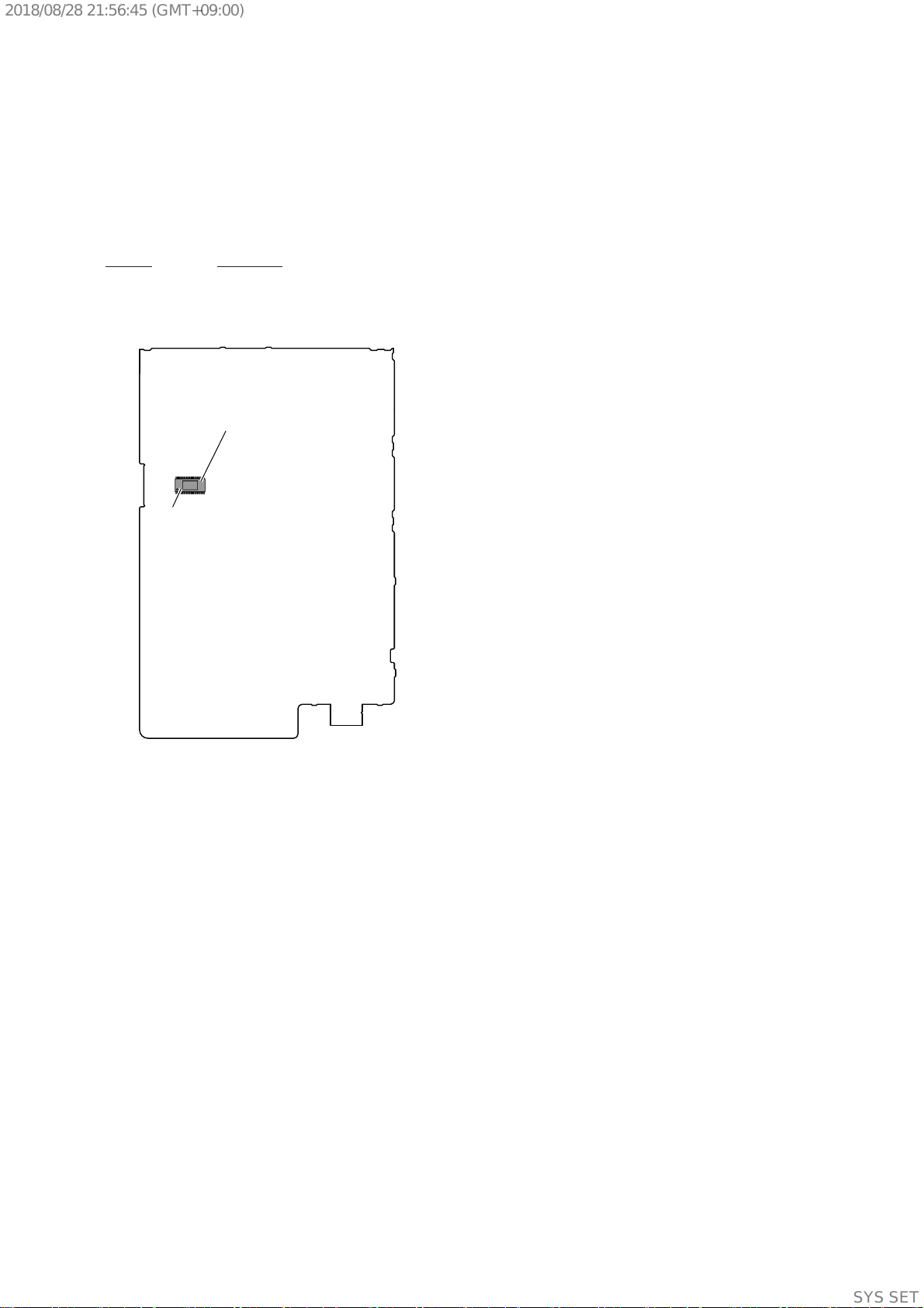
NOTE OF REPLACING THE IC2002 ON THE MOTH-
ERBOARD BOARD AND THE COMPLETE MOTHER-
BOARD BOARD
When IC2002 on the MOTHERBOARD board and the complete
MOTHERBOARD board are replaced, it is necessary to spread the
compound between parts and heat sink. After that, execute “3. IC
and MOTHERBOARD board after repair checking guide” (page
29).
Part No. Description
7-300-009-67 THERMAL COMPOUND (TIG2000)
Spread the compound referring to the fi gure below.
IC2002
thermal compound (TIG2000)
– MOTHERBOARD Board (Component Side) –
Ver. 1.1
SYSSET
2018/08/2821:56:45(GMT+09:00)
MHC-V21/V21D
8
800 :/5 W
R
800 :/5 W
R
C6301
C6322
C6505
C6506
R
800 :/5 W
R
800 :/5 W
CAPACITOR DISCHARGE FOR ELECTRIC SHOCK PREVENTION
SMPS Board (Conductor side view)
In checking the SMPS board, make 4 capacitors discharge of C6301, C6322, C6505 and C6506 for eletrical shock prevention.
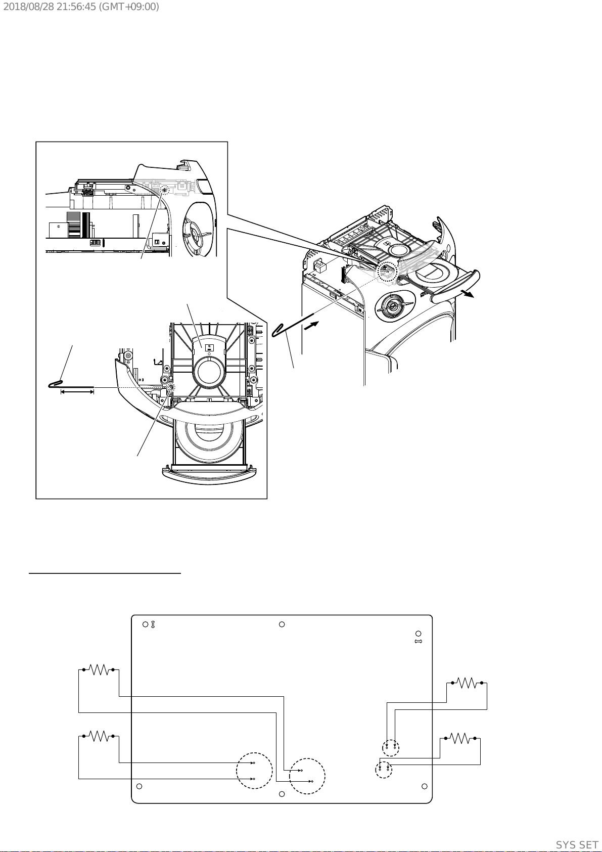
HOW TO OPEN THE TRAY WHEN POWER SWITCH TURN OFF
Note 1: After the side panel and top panel are removed, this work is done.
Note 2: Please prepare the thin wire (clip etc. processed to the length of 8 cm or more).
2 Insert the clip etc.
– Top view –
DVD mechanism
deck
tray
8 cm or more
Insert the clip etc. processed to the
length of 8 cm or more in the hole
on the side of the CDM and push.
Note:
Push after it inserts it
in this hole well.
– Left view –
hole
1 Remove the side panel L, R, top panel section.
(Illustration of disassembly is omitted.)
3
Ver. 1.1
SYSSET
2018/08/2821:56:45(GMT+09:00)
MHC-V21/V21D
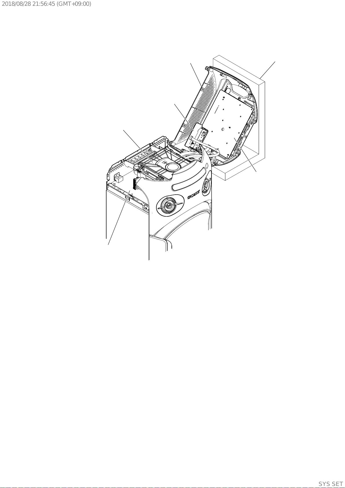
9
SERVICE POSITION
CDM90-DVBU204//M
stand
MIC USB board
PANEL board
top panel section
SMPS board
Ver. 1.1
SYSSET
2018/08/2821:56:45(GMT+09:00)
MHC-V21/V21D
10
Ver. 1.1
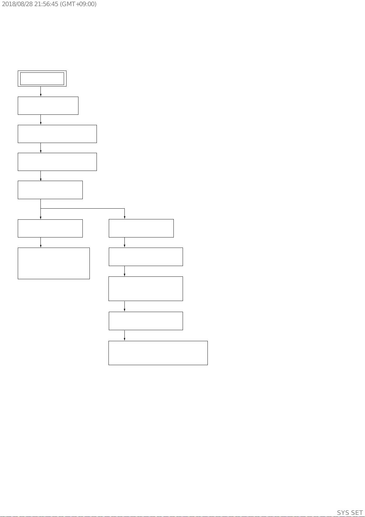
Note: Disassemble the unit in the order as shown below.
2-1. DISASSEMBLY FLOW
SECTION 2
DISASSEMBLY
2-3. TOP PANEL SECTION
(Page 12)
2-2. SIDE PANEL L, R
(Page 11)
2-5. CDM SECTION
(Page 14)
2-4. LOADING PANEL ASSY
(Page 13)
2-6. CDM90-DVBU204//M
(Page 15)
2-9. MOTHERBOARD BOARD
(Page 18)
2-11. FRONT PANEL SECTION
(Page 20)
2-7. SERVICE, OPTICAL
DEVICE (7G),
FLEXIBLE FLAT CABLE
(Page 16)
SET
2-8. BACK PANEL
(Page 17)
2-10. SMPS BOARD,
CHASSIS SECTION
(Page 19)
2-12. LOUDSPEAKER (20CM) (WOOFER)
(SP3)
(Page 21)
SYSSET
2018/08/2821:56:45(GMT+09:00)
MHC-V21/V21D
11
Ver. 1.1
Note: Follow the disassembly procedure in the numerical order given.
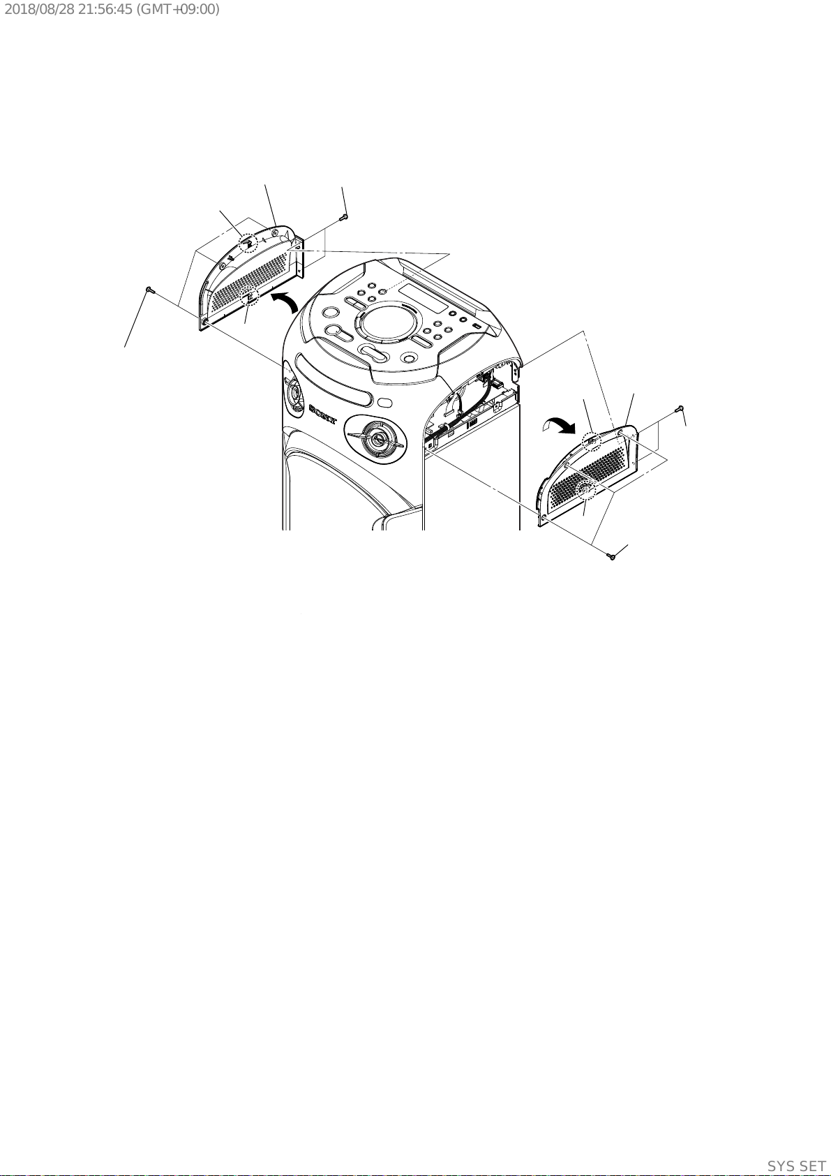
2-2. SIDE PANEL L, R
3
3
1 three
tapping screws
1 three
tapping screws
2 two screws
(+BVTP 3 u 8)
2 two screws
(+BVTP 3 u 8)
5 panel, side L
5 panel, side R
4 claw
4 claw
4 claw
4 claw
SYSSET
2018/08/2821:56:45(GMT+09:00)
MHC-V21/V21D
12
Ver. 1.1
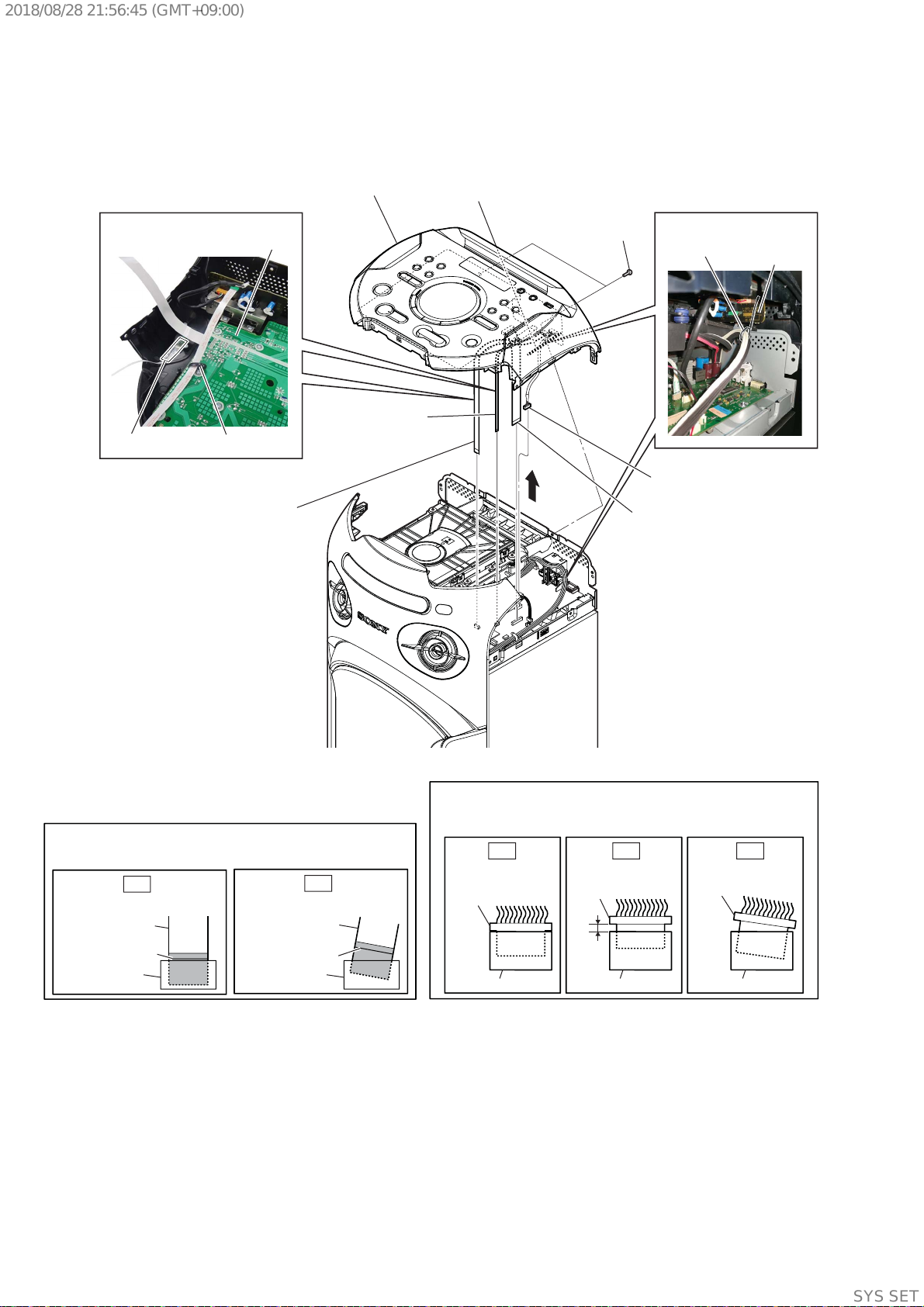
2-3. TOP PANEL SECTION
1 two screws
(+BVTP 3 u 8)
filament tape
clamp (N)
PANEL board
MIC USB
board
pin, lead
:LUHVHWWLQJ
:LUHVHWWLQJ
5 flexible flat cable
(7 core) (CN601)
4 flexible flat cable
(6 core) (CN105)
3 flexible flat cable
(15 core) (CN102)
6 Remove the wire
from pin, lead.
2 CN451 (5P)
7
8 panel, top section
Note 2:
When you install the connector, please install them correctly.
There is a possibility that this machine damages when not
correctly installing it.
Insert is shallow
Insert is straight
to the interior.
connector
Insert is incline
connector
connector
connector
connector connector
Note 1:
When installing the flexible flat cable, ensure that
the colored line is not slanted after insertion.
colored line
colored line
Insert is straight to the interior. Insert is incline
flexible flat cable flexible flat cable
connectorconnector
OK
NG
OK NG NG
SYSSET
2018/08/2821:56:45(GMT+09:00)
MHC-V21/V21D
13
Ver. 1.1
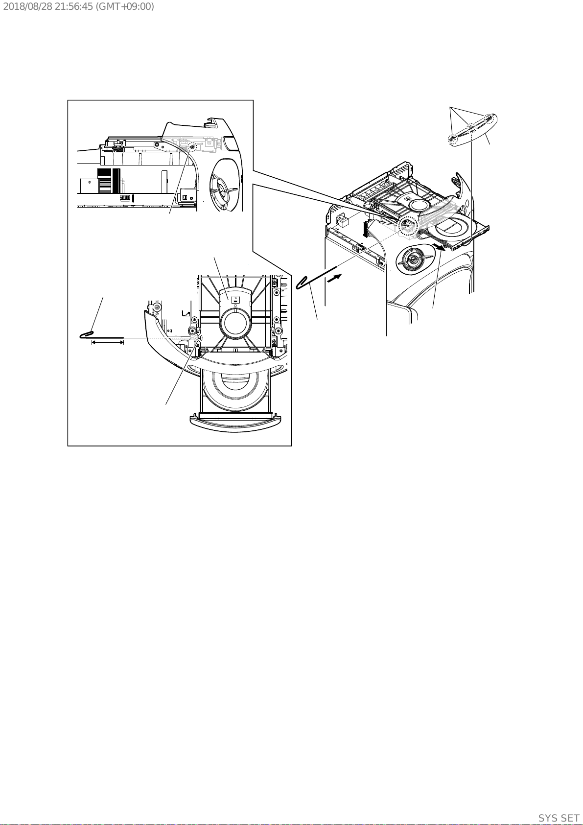
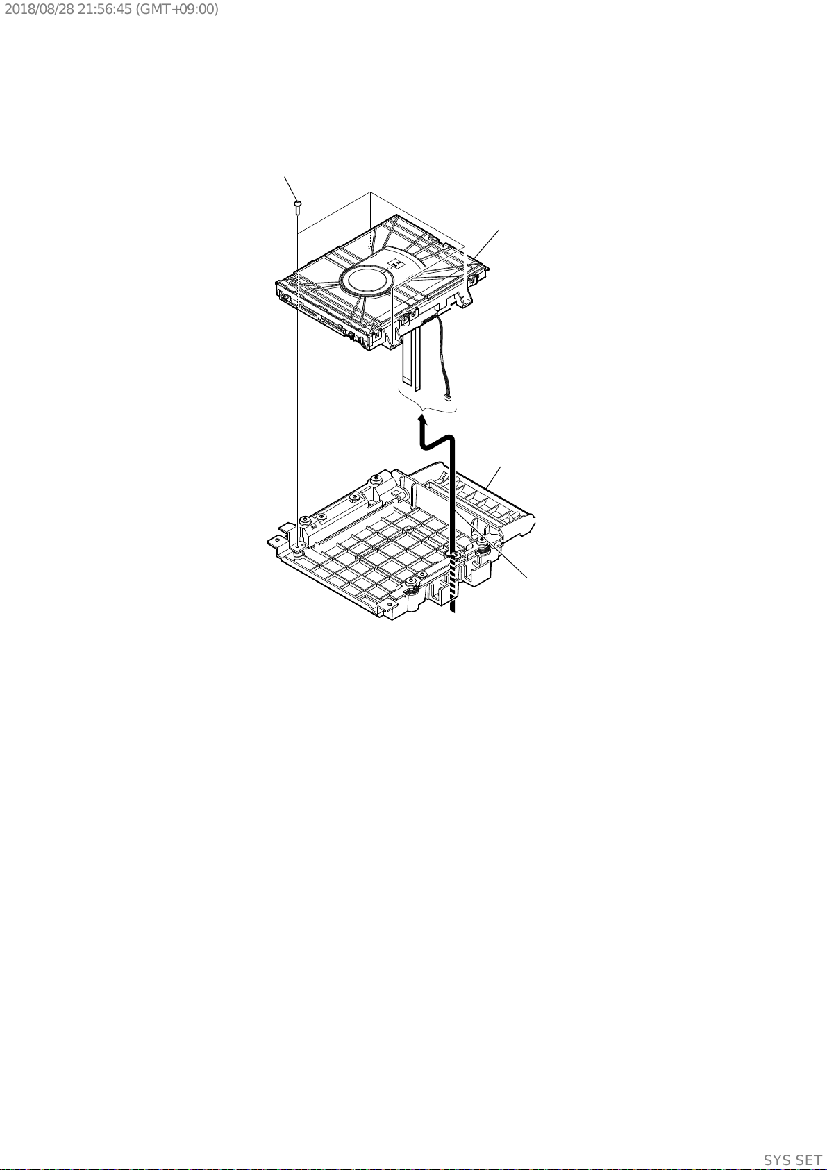
2-4. LOADING PANEL ASSY
3 three claws
4 panel, loading
assy
1 Insert the clip etc.
2 Draw out the tray.
– Top view –
DVD mechanism
deck
tray
8 cm or more
Insert the clip etc. processed to the
length of 8 cm or more in the hole
on the side of the CDM and push.
Note:
Push after it inserts it
in this hole well.
– Left view –
hole
SYSSET
2018/08/2821:56:45(GMT+09:00)
MHC-V21/V21D
14
Ver. 1.1
2-5. CDM SECTION
1 CN127 (3P)
3 CN402
(4P)
4 flexible flat cable
(5 core) (CN303)
5 flexible flat cable
(24 core) (CN302)
8 Remove the
CDM section in the
direction of the arrow.
9 CDM section
hole
hook
6 two screws
(+BVTP 3 u 8)
7 two screws
(+BVTP 3 u 8)
Note 3:
When you install the connector, please install them correctly.
There is a possibility that this machine damages when not
correctly installing it.
Note 1:
When installing the back panel
section, align two hooks and two
holes.
Insert is shallow
Insert is straight
to the interior.
connector
Insert is incline
connector
connector
connector
connector connector
Note 2:
When installing the flexible flat cable, ensure that
the colored line is not slanted after insertion.
colored line
colored line
Insert is straight to the interior. Insert is incline
flexible flat cable flexible flat cable
connectorconnector
OK
NG
OK NG NG
– Front view –
CDM section
:LUHVHWWLQJ
2 Remove the wires
from the hook.
hook
IR board
MOTHERBOARD
board
SYSSET
2018/08/2821:56:45(GMT+09:00)
MHC-V21/V21D
15
Ver. 1.1
1 four screws
(+BVTP 3 u 8)
3 CDM90-DVBU204//M
2 Draw three wires out of
the hole in bracket,CDM
section.
4 bracket, CDM section
2-6. CDM90-DVBU204//M
SYSSET
2018/08/2821:56:45(GMT+09:00)
MHC-V21/V21D
16
Ver. 1.1
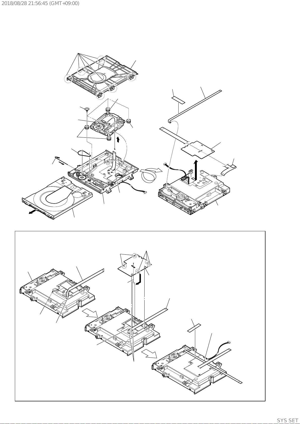
2-7. SERVICE, OPTICAL DEVICE (7G), FLEXIBLE FLAT CABLE
Under the guide
Under the guide
(Fold area)
,QVWDOODWLRQRIIOH[LEOHIODWFDEOHFRUHDQGIOH[LEOHIODWFDEOHFRUH
Note:
This illustration sees the loading assy (T) from bottom side.
1 flexible flat cable
(24 core)
2 Through the hole
3 Through the hole
4
terminal face
loading assy (T)
7 flexible flat cable
(24 core)
6 holder, FFC
5 three claws
5 two claws
9 flexible flat cable
(5 core)
8 filament tape
7 four insulator screws
9 connector
qa insulator
6 belt
3 Insert the thin
wire (clip etc.).
5 tray
qs service, optical
device (7G)
qa insulator
qa insulator
1 six claws
4
0
8
2 chuck holder assy (T)
qd base, lo assy
qh
qk flexible flat cable
(24P)
qg flexible flat cable
(5P)
qf filament tape
– Bottom view –
loading assy (T)
qj holder, FFC
SYSSET
2018/08/2821:56:45(GMT+09:00)

MHC-V21/V21D
17
Ver. 1.1
2-8. BACK PANEL
2 one screw
(+BVTP 3 u 8)
1 two screws
(+BVTP 3 u 8)
3 one screw
(+BVTP 3 u 8)
4 one screw
(+BVTP 3 u 8)
5 one screw
(+B 3 u 6)
6 panel, back
(V21D)
SYSSET
2018/08/2821:56:45(GMT+09:00)
MHC-V21/V21D
18
Ver. 1.1
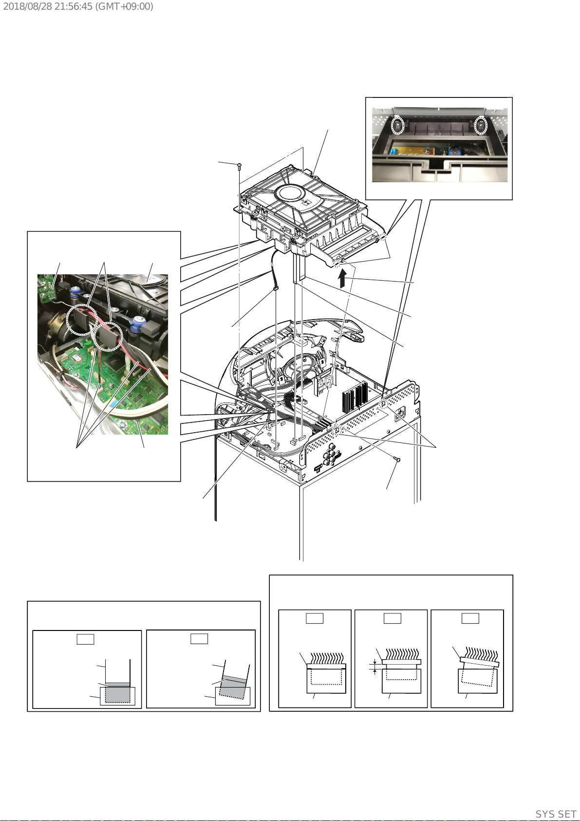
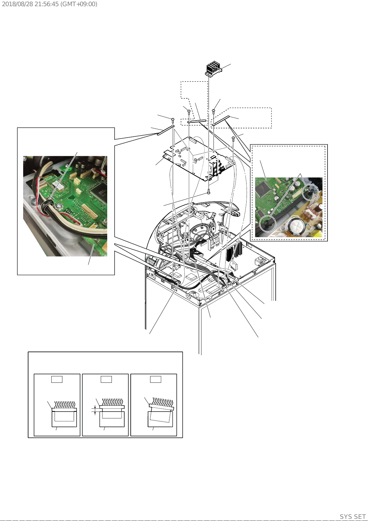
2-9. MOTHERBOARD BOARD
8 one screw
(+BVTP 3 u 8)
8 one screw
(+BVTP 3 u 8)
8 one screw
(+BVTP 3 u 8)
8 three screws
(+BVTP 3 u 8)
0 two screws
(+BVTP 3 u 8)
qa heatsink (AMP)
qs MOTHERBOARD
board
2 CN107 (2P)
5 CN001(10P)
3 CN2023
(4P)
7 CN2007
(8P)
9 clamp, (N)
9 clamp,
(N)
9 clamp, (N)
4 CN2024
(2P)
Note :
When you install the connector, please install them correctly.
There is a possibility that this machine damages when not
correctly installing it.
Insert is shallow
Insert is straight
to the interior.
connector
Insert is incline
connector
connector
connector
connector connector
OK NG NG
:LUHVHWWLQJ
:LUHVHWWLQJ
1 Remove the wires
from clamp (N).
6 Remove the wires
from clamp (N).
MOTHERBOARD board
MOTHERBOARD board
(V21)
(V21)
(V21)
SYSSET
2018/08/2821:56:45(GMT+09:00)
MHC-V21/V21D
19
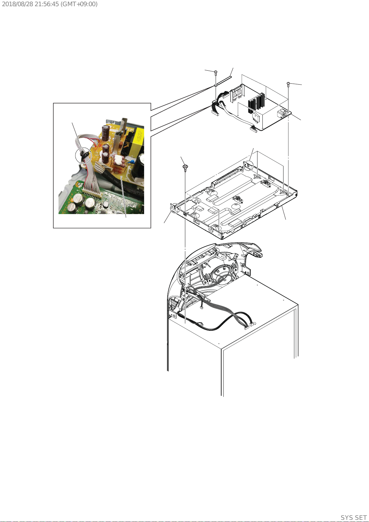
Ver. 1.1
4 four step screws
M4
2 clamp (N)
3 SMPS board
6 chassis section
5 claw
5 claw
:LUHVHWWLQJ
clamp (N)
SMPS board
1 one screw
(+BVTP 3 u 8)
1 five screws
(+BVTP 3 u 8)
2-10. SMPS BOARD, CHASSIS SECTION
SYSSET
2018/08/2821:56:45(GMT+09:00)
 Loading...