


3-866-222-11(1)
Mini Hi-Fi
Component
System
Operating Instructions
Owner’s Record
The model and serial numbers are located on the rear panel. Record the serial number in the space provided below. Refer to them whenever you call upon your Sony dealer regarding this product.
Model No. |
|
Serial No. |
f
MHC-RXD6AV
MHC-GRX40AV
©1999 by Sony Corporation |
1 |
|
WARNING
To prevent fire or shock hazard, do not expose the unit to rain or moisture.
To avoid electrical shock, do not open the cabinet. Refer servicing to qualified personnel only.
Do not install the appliance in a confined space, such as a bookcase or built-in cabinet.
This appliance is classified as a CLASS 1 LASER product. The CLASS 1 LASER PRODUCT MARKING is located on the rear exterior.
NOTICE FOR THE CUSTOMERS IN THE U.S.A.
This symbol is intended to alert the user to the presence of uninsulated “dangerous voltage” within the product’s enclosure that may be of sufficient magnitude to constitute a risk of electric shock to persons.
This symbol is intended to alert the user to the presence of important operating and maintenance (servicing) instructions in the literature accompanying the appliance.
CAUTION
The use of optical instruments with this product will increase eye hazard.
INFORMATION
This equipment has been tested and found to comply with the limits for a Class B digital device, pursuant to Part 15 of the FCC Rules. These limits are designed to provide reasonable protection against harmful interference in a residential installation. This equipment generates, uses, and can radiate radio frequency energy and, if not installed and used in accordance with the instructions, may cause harmful interference to radio communications. However, there is no guarantee that interference will not occur in a particular installation. If this equipment does cause harmful interference to radio or television reception, which can be determined by turning the equipment off and on, the user is encouraged to try to correct the interference by one or more of the following measures:
–Reorient or relocate the receiving antenna.
–Increase the separation between the equipment and receiver.
–Connect the equipment into an outlet on a circuit different from that to which the receiver is connected.
–Consult the dealer or an experienced radio/TV technician for help.
CAUTION
You are cautioned that any changes or modifications not expressly approved in this manual could void your authority to operate this equipment.
Note to CATV system installer:
This reminder is provided to call the CATV system installer’s attention to Article 820–40 of the NEC that provides guidelines for proper grounding and, in particular, specifies that the cable ground shall be connected to the grounding system of the building, as close to the point of cable entry as practical.
NOTICE FOR THE CUSTOMERS IN CANADA
CAUTION:
TO PREVENT ELECTRIC SHOCK, DO NOT USE THIS POLARIZED AC PLUG WITH AN EXTENSION CORD, RECEPTACLE OR OTHER OUTLET UNLESS THE BLADES CAN BE FULLY INSERTED TO PREVENT BLADE EXPOSURE.
This stereo system is equipped with the Dolby Pro Logic Surround decoder*.
* Manufactured under license from Dolby Laboratories Licensing Corporation. DOLBY, the double-D symbol aand “PRO
LOGIC” are trademarks of Dolby Laboratories Licensing Corporation.
2

Table of Contents |
|
Getting Started |
|
Step 1: Hooking up the main unit |
....... 4 |
Step 2: Setting up your speakers ......... |
5 |
Step 3: Setting the time ......................... |
9 |
Step 4: Presetting radio stations ........ |
10 |
Connecting optional AV |
|
components .................................... |
12 |
Connecting outdoor antennas ............ |
13 |
Basic Operations |
|
Playing a CD ......................................... |
14 |
Recording a CD .................................... |
16 |
Listening to the radio ........................... |
17 |
Recording from the radio .................... |
19 |
Playing a tape ........................................ |
20 |
The CD Player |
|
Using the CD display ........................... |
22 |
Playing the CD tracks repeatedly ...... |
23 |
Playing the CD tracks in random |
|
order ................................................ |
24 |
Programming the CD tracks ............... |
25 |
The Tape Deck |
|
|
Recording on a tape manually ........... |
26 |
|
Recording CDs by specifying track |
|
|
order ................................................ |
|
27 |
Sound Adjustment |
|
|
Adjusting the sound ............................ |
|
29 |
Selecting the audio emphasis |
............. |
30 |
Selecting surround effects ................... |
|
31 |
Enjoying Dolby Pro Logic Surround |
|
|
sound ............................................... |
|
32 |
Other Features |
|
|
Falling asleep to music ........................ |
|
33 |
Waking up to music ............................. |
|
33 |
Timer-recording radio programs ....... |
35 |
|
Additional Information |
|
|
Precautions ............................................ |
|
36 |
Troubleshooting ................................... |
|
38 |
Specifications ........................................ |
|
40 |
Index ........................................ |
back cover |
|
3
Getting Started
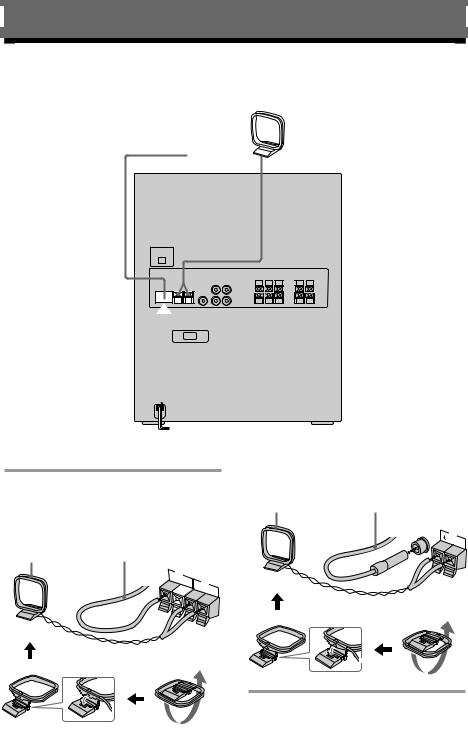
Step 1: Hooking up the main unit
AM loop antenna
FM antenna
/
/Connect the FM/AM antennas. |
Jack type B |
|
||
|
Extend the FM lead |
|||
Set up the AM loop antenna, then |
|
|||
AM loop antenna |
antenna horizontally. |
|||
connect it. |
|
|||
|
|
FM |
||
Jack type A |
|
|
||
|
|
75Ω |
||
|
|
AM |
||
|
Extend the FM lead |
|
|
|
AM loop antenna |
antenna horizontally. |
|
|
|
75Ω
FM

 AM
AM
4
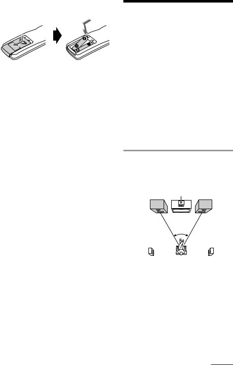
Inserting two R03 (size AAA) batteries into the remote
Tip
With normal use, the batteries should last for about six months. When the remote no longer operates the system, replace both batteries with new ones.
Note
If you do not use the remote for a long period of time, remove the batteries to avoid possible damage from battery leakage.
Step 2: Setting up your speakers
Connecting the supplied rear and center surround speakers enables you to fully enjoy Dolby Pro Logic Surround sound. Dolby Pro Logic Surround is a decoding system standardized in TV programs and movies. Dolby Pro Logic Surround improves the sound image by using four separate channels. These channels manipulate the sound to be heard and enhance the action as it happens on the screen.
Positioning the speakers
Before you connect them, determine the best location for your speakers.
1 Place the front speakers at an angle of 45 degrees from your listening position.
|
Center |
|
Front |
surround |
Front |
speaker (L) |
speaker |
speaker (R) |
|
45° |
|
Rear surround |
|
Rear surround |
speaker (L) |
|
speaker (R) |
continued
5
Step 2: Setting up your speakers (continued)
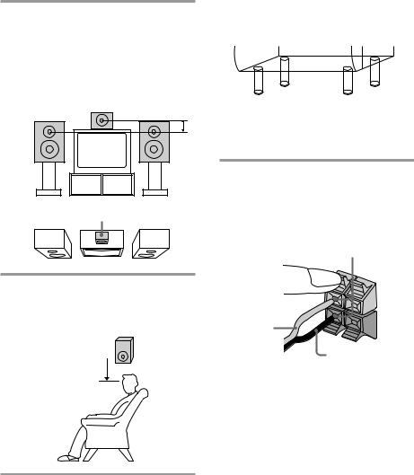
2 Place the center speaker so it is placed about the same height as the front speakers (A). Align the center surround speaker with the front speakers or place it slightly back from the position of the front speakers (B).
A
B
Center surround speaker
3 Place the rear surround speakers facing each other at about 60 to 90 cm (2 to 3 feet) above your listening position.
Rear surround
60 to 90 cm  speaker (2 to 3 feet)
To attach the speaker pads
Attach the supplied speaker pads to the bottom of the center surround speaker to stabilize the speaker and prevent it from slipping.
Connecting the speakers
(Refer to illustration at right.)
1Connect the front speakers.
Connect the speaker cords to the FRONT SPEAKER jacks of the same color.
Keep the speaker cords away from the antennas to prevent noise.
Insert only the stripped portion.
L
|
+ |
Red (‘) |
– |
|
|
|
Black (’) |
Note
The type of speakers supplied vary according to the model you purchased (see “Specifications” on page 40).
6

Rear surround speaker (Right) |
Rear surround speaker (Left) |
Center surround speaker
Front speaker (Right)
2Connect the rear surround speakers.
Connect the speaker cords from the rear surround speakers to the appropriate REAR SPEAKER jacks. Connect the solid cords to the red jacks and connect the striped cords to the black jacks.
Keep the speaker cords away from the antennas to prevent noise.
Front speaker (Left)
Notes
•Do not place the rear surround speakers on top of a TV. This may cause distortion of the colors in the TV screen.
•Be sure to connect both left and right rear surround speakers. Otherwise, the sound will not be heard.
Insert only the stripped portion.
Solid (‘)
R
L
+ –
Stripe (’)
continued
7

Step 2: Setting up your speakers (continued)
3Connect the center surround speaker.
Connect the speaker cords to the appropriate CENTER SPEAKER jacks. Connect the solid cord to the red jack and connect the striped cord to the black jack.
Keep the speaker cords away from the antennas to prevent noise.
Insert only the stripped portion.
R |
L |
|
|
+ |
Solid (‘) |
– |
|
|
|
Stripe (’) |
4Connect the power cord to a wall outlet.
Demo mode appears in the display.
5Deactivate the demo mode by pressing DEMO when the system is turned off.
The demo mode is also deactivated when you set the time.
Tip
You can reinforce the bass sound by connecting an optional super woofer to the super woofer connector.
Adjusting the speaker volume
To enjoy Dolby Pro Logic Surround sound, turn the Dolby Pro Logic mode on, then adjust the volume of each speaker using the test tone that the system provides.
1/u (Power)
1
(
P p
(= +
(0 )
2
1
3
8
1 Press DOLBY PROLOGIC (or PRO LOGIC ON/OFF on the remote).
“PRO LOGIC ON” appears.
2 Press T.TONE ON/OFF on the remote.
The test tone is heard from the speakers |
||||
in the following order. Adjust the |
||||
volume of the test tone. |
||||
Front (left) nCenter nFront (right) |
||||
n |
Rear |
|
|
|
|
|
|
|
|
|
|
n |
||
|
|
|
|
|
3 From your listening position, press CENTER +/– and REAR +/– on the remote to adjust the volume.
The volume levels from each speaker must become the same.
4 Press T.TONE ON/OFF when you are done adjusting.
The test tone turns off.
Tip
If you turn VOLUME (or press VOL +/– on the remote) all the speaker volumes change.
Note
The test tone feature works only for Dolby Pro Logic Surround sound.
Step 3: Setting the time
You must set the time before using the timer functions.
The clock is on a 24-hour system for the European and Russian models, and a 12-hour system for other models.
The 12-hour system model is used for illustration purposes.
12,4 3,5
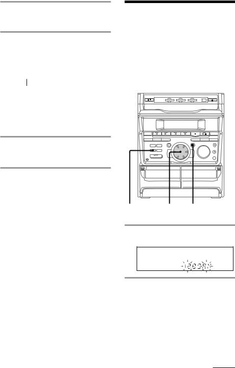
1Press CLOCK/TIMER SET.
The hour indication flashes.
2Turn the jog dial to set the hour.
continued
9
Step 3: Setting the time (continued)
3 Press ENTER/NEXT.
The minute indication flashes.
4 Turn the jog dial to set the minute.
5 Press ENTER/NEXT.
The clock starts working.
Tips
•If you’ve made a mistake, start over from step 1.
•Setting the time deactivates the demo mode. If you want to display the demo mode, press DEMO when the system is off.
Note
The previous explanation shows you how to set the time while the system is off. To change the time while the system is on, do the following:
1 Press CLOCK/TIMER SET.
2 Turn the jog dial to select “SET CLOCK”. 3 Press ENTER/NEXT.
4 Perform steps 2 through 5 above.
Step 4: Presetting radio stations
You can preset up to 30 stations, 20 for FM and 10 for AM.
1/u |
3 |
1 |
(Power) |
24
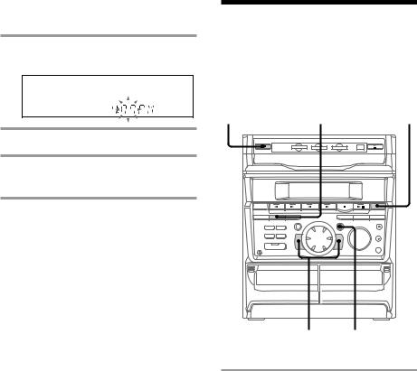
1Press TUNER/BAND repeatedly until the band you want appears in the display.
Every time you press this button, the
band changes as follows: FM ˜AM
10
2 Press and hold + or – until the frequency indication starts to change, then release.
Scanning stops when the system tunes in a station. “TUNED” and “STEREO” (for a stereo program) appear.
MONO TUNED
STEREO
|
|
VOLUME |
ALL DISCS |
kHz |
|
|
MHz |
ß |
3 Press TUNER MEMORY.
A preset number flashes in the display.
Preset number
VOLUME
ALL DISCS
ß
4 Press ENTER/NEXT.
The station is stored.
5 Repeat steps 1 to 4 to store other stations.
To tune in a station with a weak signal
Press + or – repeatedly in step 2 to tune in the station manually.
To set another station to the exist preset number
Start over from step 1. After step 3, press + or
– repeatedly to select the preset number you want to store the station.
To erase a preset number
1Press and hold TUNER MEMORY until the preset number flashes in the display.
2Press + or – repeatedly to select the preset number you want to erase.
If you want to erase all preset numbers, select “ALL ERASE”.
3Press ENTER/NEXT.
When you erase a preset number, the total number of preset stations decreases by one. You can add a new preset number after the last preset number.
Tip
The preset stations are retained for half a day even if you unplug the power cord or if a power failure occurs.
11

Connecting optional AV components
To enhance your system, you can connect optional components. Refer to the instructions of each component.
Connecting audio components
Select one of the following two connections, depending on the equipment to be connected and method of recording.
Connecting an MD deck for digital recording
You can record from CD into the MD deck digitally by connecting an optical cable.
To the DIGITAL IN jack of the MD deck
Connecting an MD deck for analog recording
Make sure to match the color of the plugs and the connectors. To listen to the sound of the connected MD deck, press FUNCTION repeatedly until “MD” appears.
To the audio input |
|
To the audio output |
|||||||||||||||||||||
of the MD deck |
|
of the MD deck |
|||||||||||||||||||||
|
|
|
|
|
|
|
|
|
|
|
|
|
|
|
|
|
|
|
|
|
|
|
|
Note
If you cannot select “MD” by pressing FUNCTION, press 1/uwhile pressing FUNCTION when the system is turned off. “VIDEO” will be switched to “MD”. To return to “VIDEO”, do the same procedure.
12
Connecting a super woofer speaker
You can connect an optional super woofer speaker.
To super woofer
Connecting a VCR
Make sure to match the color of the plugs and the connectors. To listen to the sound of the connected VCR, press FUNCTION repeatedly until “VIDEO” appears.
To the audio output of the VCR
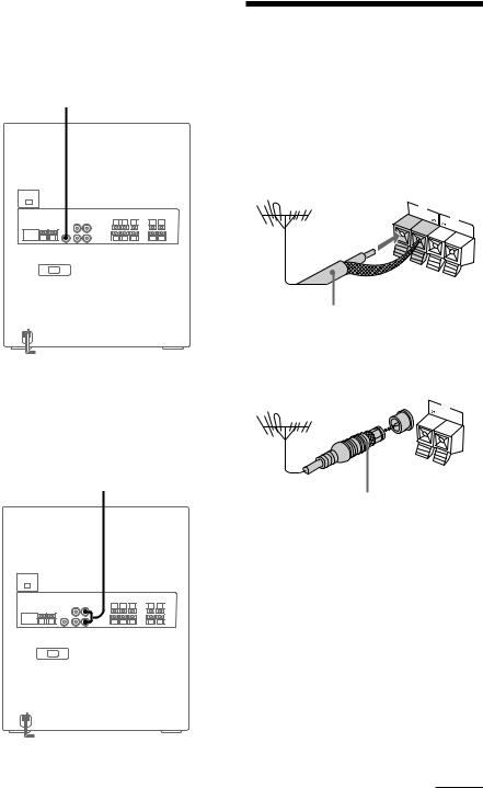
Connecting outdoor antennas
Connect the outdoor antenna to improve the reception.
FM antenna
Connect the optional FM outdoor antenna. You can also use the TV antenna instead.
Jack type A
75Ω |
FM |
|
AM
75-ohm coaxial cable (not supplied)
Jack type B
FM 75Ω
AM
IEC standard socket connector
(not supplied)
continued
13

Connecting outdoor antennas (continued)
AM antenna
Connect a 6- to 15meter (20to 50feet) insulated wire to the AM antenna terminal. Leave the supplied AM loop antenna connected.
Jack type A
Insulated wire (not supplied)
75Ω |
FM |
|
AM
Jack type B
Insulated wire (not supplied)
FM 75Ω
AM
Basic Operations
Playing a CD
— Normal play
You can play up to three CDs in a row.
1/u
(Power) |
p (P 2 |
DISC SKIP/ |
1 |
||||||||||
EX-CHANGE |
|||||||||||||
|
|
|
|
|
|
|
|
|
|
|
|
|
|
|
|
|
|
|
|
|
|
|
|
|
|
|
|
|
|
|
|
|
|
|
|
|
|
|
|
|
|
|
|
|
|
|
|
|
|
|
|
|
|
|
|
|
|
|
|
|
|
|
|
|
|
|
|
|
|
|
|
|
|
|
|
|
|
|
|
|
|
|
|
|
|
|
|
|
|
|
|
|
|
|
|
|
|
|
|
|
|
|
|
|
|
|
|
|
|
|
|
|
|
|
|
|
|
|
|
|
|
|
|
|
|
|
|
|
|
|
|
|
|
|
|
|
|
|
|
|
|
|
|
|
|
|
|
|
|
|
|
|
|
PLAY Jog dial 0/) VOLUME MODE
CD ( |
( |
|
|
P |
|
P |
p |
p |
|
|
|
|||
|
( |
= + |
||
|
=/+ |
|||
|
( |
0 |
) |
|
|
|
|||
VOL +/–
14
 Loading...