


SIMODRIVE 611 Analog System Transistor PWM Inverters for AC Feed Drives and
AC Main Spindle Drives
Installation and Start±up Guide |
04.97 Edition |
Service Documentation
SIMODRIVE 611 Analog System Transistor PWM Inverters for AC Feed Drives and
AC Main Spindle Drives
Start±Up Guide
Service Documentation
Valid for
Equipment series 6SN11±
Foreword
|
|
|
|
General information |
AL |
|
|
|
|
|
|
|
|
||
Supply infeed |
NE |
|
|
|
|
||
|
|
||
Feed modules |
VS |
|
|
|
|
|
|
Feed modules, |
|
|
|
VR |
|
|
|
resolver control |
|
||
|
|
||
|
|
||
Main spindle modules |
HS |
|
|
|
|
||
|
|
||
Induction motor modules |
AM |
|
|
|
|
||
|
|
||
Spare parts |
ES |
|
|
|
|
|
|
Complete index |
|
|
|
|
|
|
|
04.97 Edition
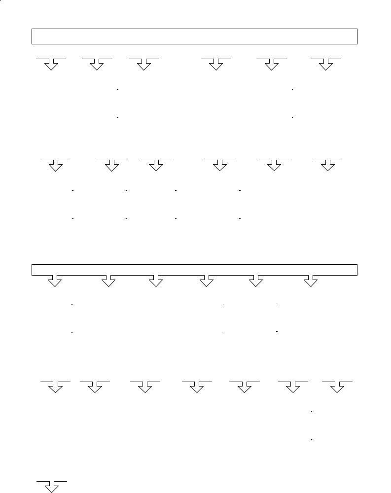
Overview of SINUMERIK 840D/810D/FM±NC Documentation (08.97)
|
General Documentation |
|
|
|
|
|
|
|
User Documentation |
|
|
|
|
|||||||||||||||
|
|
|
|
|
|
|
|
|
|
|
|
|
|
|
|
|
|
|
|
|
|
|
|
|
|
|
|
|
|
|
|
|
|
|
|
|
|
|
|
|
|
|
|
|
|
|
|
|
|
|
|
|
|
|
|
|
|
|
|
|
|
|
|
|
|
|
|
SINUMERIK |
|
|
|
|
|
|
|
|
|
|
|
|
|
|
|
|
||
|
|
|
|
|
|
|
|
|
|
|
SIROTEC |
|
|
|
|
|
|
|
|
|
|
|
|
|
|
|
|
|
|
SINUMERIK |
|
|
|
|
SINUMERIK |
|
|
SIMODRIVE |
|
|
|
|
SINUMERIK |
|
|
SINUMERIK |
|
|
|
SINUMERIK |
|
||||||
|
|
|
|
|
|
|
|
|
|
|
|
|
|
|
|
|
|
|
|
|
|
|
|
|
|
|
|
|
|
840D/810D/ |
|
|
|
|
840D/810D/ |
|
|
|
|
Accessories |
|
|
|
|
|
840D/810D/ |
|
|
|
840D/810D/ |
|
|
|
|
840D/810D/ |
|
|
|
FM±NC |
|
|
|
|
FM±NC/611 |
|
|
|
|
|
|
|
|
|
|
FM±NC |
|
|
|
FM±NC |
|
|
|
|
FM±NC |
|
|
|
|
|
|
|
|
|
|
|
|
|
|
|
|
|
|
|
|
|
|
|
|
|
|
|
|
|
|
|
|
|
|
|
|
|
|
|
|
|
|
|
|
|
|
|
|
|
|
|
|
|
|
|
|
|
|
|
|
|
|
|
|
|
|
|
|
|
|
|
|
|
|
|
|
|
|
|
|
|
|
|
|
|
|
|
||
Brochure |
Catalog |
|
Catalog |
|
AUTOTURN |
|
Operator's Guide |
Diagnostics Guide |
||||||||||||||||||||
|
|
Ordering Info. NC 60.1 |
|
Accessories NC±Z |
|
± Short Guide |
|
± Unit Operator Panel |
|
|
|
|
||||||||||||||||
|
|
Technical Info. NC 60.2 |
|
|
|
|
|
|
± Programming (Part 1) ± HPU |
|
|
|
|
|||||||||||||||
|
|
|
|
|
|
|
|
|
|
|
|
|
|
|
|
± Setup (Part 2) |
|
|
|
|
|
|
|
|
|
|
||
|
User Documentation |
|
|
|
|
|
|
|
Manufacturer / Service Documentation |
|||||||||||||||||||
|
|
|
|
|
|
|
|
|
|
|
|
|
|
|
|
|
|
|
|
|
|
|
|
|
|
|
|
|
|
|
|
|
|
|
|
|
|
|
|
|
|
|
|
|
|
|
|
|
|
|
|
|
|
|
|
|
|
|
SINUMERIK |
|
|
|
SINUMERIK |
|
|
|
SINUMERIK |
|
|
|
SINUMERIK |
|
|
|
SINUMERIK |
|
|
SINUMERIK |
||||||||
|
|
|
|
|
|
|
|
|
|
|
|
|
|
|
|
|
|
|
|
|
|
|
|
|
|
|
|
|
|
|
840D/810D/ |
|
|
|
|
|
840D/810D/ |
|
|
|
|
810D |
|
|
|
|
810D |
|
|
|
|
840D/810D/ |
|
|
|
840D/810D |
|
|
|
FM±NC |
|
|
|
|
|
FM±NC |
|
|
|
|
|
|
|
|
|
|
|
|
|
|
FM±NC |
|
|
|
|
|
|
|
|
|
|
|
|
|
|
|
|
|
|
|
|
|
|
|
|
|
|
|
|
|
|
|
|
|
|
|
|
|
|
|
|
|
|
|
|
|
|
|
|
|
|
|
|
|
|
|
|
|
|
|
|
|
|
|
|
|
|
|
|
|
|
|
|
|
|
|
|
|
|
|
|
|
|
|
|
|
|
|
|
|
|
|
|
Operator's Guide |
Programming Guide |
Operator's Guide |
Description of |
Description of |
Description of |
± Short Guide |
± Short Guide |
± MANUALTURN |
Functions |
Functions |
Functions |
± Operator's Guide |
± Fundamentals |
± SHOPMILL |
± MANUALTURN |
Synchronous |
Computer LInk |
|
± Advanced |
|
± SHOPMILL |
actions |
|
|
± Cycles |
|
|
Wood, Glass, |
|
|
± Measuring Cycles |
|
|
Ceramics |
|
Manufacturer / Service Documentation
|
|
|
|
|
|
|
|
|
|
|
|
|
|
|
|
|
|
|
|
|
|
|
|
|
|
|
|
|
|
SINUMERIK |
|
|
|
SINUMERIK |
|
|
SIMODRIVE |
|
SINUMERIK |
|
|
|
|
SINUMERIK |
|
|
|
SINUMERIK |
|||||||
|
|
|
|
|
|
|
SINUMERIK |
|
|
|
|
|
|
|
|
||||||||||||
|
|
|
|
|
|
|
|
|
|
|
|
|
|||||||||||||||
|
|
|
|
|
|
|
|
|
|
|
|
|
|||||||||||||||
|
|
|
|
|
|
|
|
|
|
|
|
|
|
|
|
|
|
|
|
|
|
|
|
|
|
|
|
|
|
|
|
|
|
|
840D/810D/ |
|
|
|
611D |
|
|
|
840D/810D/ |
|
|
|
|
|
840D/810D/ |
|
|
|
|
840D/810D/ |
|
|
|
|
|
|
|
|
FM±NC |
|
|
|
840D/810D |
|
|
|
FM±NC |
|
|
|
|
|
FM±NC |
|
|
|
|
FM±NC |
|
|
|
|
|
|
|
|
|
|
|
|
|
|
|
|
|
|
|
|
|
|
|
|
|
|
|
|
|
|
|
|
|
|
|
|
|
|
|
|
|
|
|
|
|
|
|
|
|
|
|
|
|
|
|
|
|
|
|
|
|
|
|
|
|
|
|
|
|
|
|
|
|
|
|
|
|
|
|
|
|
|
|
|
|
|
|
|
|
|
|
|
|
|
|
|
|
|
|
|
|
|
|
|
|
|
|
|
|
|
|
|
|
|
Manual |
|
|
Manual |
|
Description of |
|
Description of |
|
Configuring KIt |
Screen Kit |
|
|
|
|||||||||||||||||||
|
Configuring (HW) |
|
Operator |
|
Functions |
|
Functions |
|
MMC100/101 |
|
|
|
MMC100/101 |
|
|||||||||||||||||||
|
± FM±NC |
|
|
Components |
|
Drive Functions |
|
± Basic Machine |
|
± Configuring Syntax |
SW Update and |
|
|||||||||||||||||||||
|
± 810D |
|
|
(HW) |
|
|
|
|
|
± Extended Functions ± Development Kit |
Configuration |
|
|||||||||||||||||||||
|
± 840D |
|
|
|
|
|
|
|
|
|
|
± Special Functions |
|
|
|
|
|
|
|
|
|
|
|
||||||||||
|
|
Manufacturer / Service Documentation |
|
|
|
|
|
|
|
|
|
|
|
|
|
|
|
|
|
|
|
||||||||||||
|
|
|
|
|
|
|
|
|
|
|
|
|
|
|
|
|
|
|
|
|
|
|
|
|
|
|
|
|
|
|
|
|
|
|
|
|
|
|
|
|
|
|
|
|
|
|
|
|
|
|
|
|
|
|
|
|
|
|
|
|
|
|
|
|
|
|
|
|
|
|
|
|
|
|
|
|
|
|
|
|
|
|
|
|
|
|
|
|
|
|
|
|
|
|
|
|
|
|
|
|
|
|
|
|
|
|
|
|
|
|
|
|
|
|
|
|
|
SIMODRIVE |
|
|
|
|
|
SIMODRIVE |
|
|
|
SIMODRIVE |
|
||||||
|
|
|
|
|
|
|
|
|
|
|
|
|
|
|
|
|
|
|
|
|
|
|
|
SINUMERIK |
|
||||||||
|
|
SINUMERIK |
|
|
SINUMERIK |
|
|
SINUMERIK |
|
|
SINUMERIK |
|
|
SINUMERIK |
|
|
|
SINUMERIK |
|
|
|
|
|
|
|||||||||
|
|
|
|
|
|
|
|
|
|
840D/810D |
|
|
|||||||||||||||||||||
|
|
|
|
|
|
|
|
|
|
|
|
|
|
|
|
|
|
|
|
|
|
|
|
|
|
|
|
|
|
|
|
|
|
|
|
840D/810D |
|
|
|
840D/810D/ |
|
|
|
840D/810D |
|
|
|
|
|
|
|
840D |
|
|
|
|
|
|
|
|
|
|
FM±NC |
|
|
||
|
|
|
|
|
|
|
|
|
|
|
|
|
|
|
|
|
|
|
|
|
|
|
|
|
611D |
|
|
||||||
|
|
|
|
|
|
|
|
FM±NC |
|
|
|
|
|
|
|
|
|
|
|
|
|
|
|
|
|
|
|
|
|
|
|
|
|
|
|
|
|
|
|
|
|
|
|
|
|
|
|
|
|
|
|
|
|
|
|
|
|
|
|
|
|
|
|
|
|
|
|
|
|
|
|
|
|
|
|
|
|
|
|
|
|
|
|
|
|
|
|
|
|
|
|
|
|
|
|
|
|
|
|
|
|
|
|
|
|
|
|
|
|
|
|
|
|
|
|
|
|
|
|
|
|
|
|
|
|
|
|
|
|
|
|
|
|
|
|
|
|
|
|
|
|
|
|
|
|
|
|
|
|
|
|
|
|
|
|
|
|
|
|
|
|
|
|
|
|
|
|
|
|
|
|
|
|
|
|
|
|
|
|
|
|
|
|
|
|
|
|
|
|
|
|
|
|
|
|
|
|
|
|
|
|
|
|
|
|
|
|
|
|
|
|
|
|
|
|
|
|
|
|
|
|
|
|
|
|
|
|
|
|
|
|
|
|
|
|
|
|
|
Description of |
|
Description of |
Description of |
Description of |
Description of |
Installation & |
Lists |
|
||||||||||||||||||||||||
|
Functions |
|
Functions |
Functions |
Functions |
Functions |
Start-up Guide |
|
|
|
|||||||||||||||||||||||
|
Tool Manage- |
|
Operator Interface |
Operator Interface |
SINUMERIK |
Digitizing |
± FM±NC |
|
|
|
|
|
|
|
|
||||||||||||||||||
|
ment |
|
OP 030 |
HPU |
Safety Integrated |
|
|
|
|
± 810D |
|
|
|
|
|
|
|
|
|||||||||||||||
|
|
Electronic Documentation |
|
|
|
|
|
|
|
|
|
|
|
|
± 840D/611D |
|
|
|
|||||||||||||||
|
|
|
|
|
|
|
|
|
|
|
|
|
|
|
|
|
|
|
|
|
|
|
|
|
|
|
|
|
|
|
|
|
|
|
|
|
|
|
|
|
|
|
|
|
|
|
|
|
|
|
|
|
|
|
|
|
|
|
|
|
|
|
|
|
|
|
|
|
|
SINUMERIK |
|
|
|
|
|
|
|
|
|
|
|
|
|
|
|
|
|
|
|
|
|
|
|
|
|
|
|
|
|
|
|
|
|
SIMODRIVE |
|
|
|
|
|
|
|
|
|
|
|
|
|
|
|
|
|
|
|
|
|
|
|
|
|
|
|
|
|
||
|
|
|
|
|
|
|
|
|
|
|
|
|
|
|
|
|
|
|
|
|
|
|
|
|
|
|
|
|
|
|
|
|
|
|
|
840D/810D/ |
|
|
|
DOC ON CD |
|
|
|
|
|
|
|
|
|
|
|
|
|
|
|
|
|
|
|
|
|
|
|
||||
|
|
FM±NC |
|
|
|
|
|
|
|
|
|
|
|
|
|
|
|
|
|
|
|
|
|
|
|
|
|
||||||
|
|
611, Motors |
|
|
The SINUMERIK System |
|
|
|
|
|
|
|
|
|
|
|
|
|
|
|
|
|
|
|
|||||||||
|
|
|
|
|
|
|
|
|
|
|
|
|
|
|
|
|
|
|
|
|
|
|
|
|
|
|
|
|
|
|
|
|
|

3ls SIMODRIVE documentation
Edition coding
Brief details of this edition and previous editions are listed below
The status of each edition is shown by the code in the ºRemarksº column.
Status code in the ºRemarksº column:
A . . . . New documentation.
B . . . . Unrevised reprint with new Order No. C . . . . Revised edition with new status
If factual changes have been made on the page since the last edition, this is indicated by a new edition coding in the header on that page.
07.94 |
6SN1197±0AA60±0BP0 |
A |
10.94 |
6SN1197±0AA60±0BP1 |
C |
12.94 |
6SN1197±0AA60±0BP2 |
C |
03.96 |
6SN1197±0AA60±0BP3 |
C |
04.97 |
6SN1197±0AA60±0BP4 |
C |
Dieses Buch ist Bestandteil der Dokumentation auf CD±ROM (DOCONCD)
09.97 |
6FC5 198±6CA00±0AG0 |
(840C Read) |
C |
09.97 |
6FC5 198±6CB00±0AG0 |
(840C Print) |
C |
09.97 |
6FC5 198±6CC00±0AG0 |
(840C Net) |
C |
09.97 |
6FC5 298±4CA00±0AG0 |
(840D Read) |
C |
09.97 |
6FC5 298±4CB00±0AG0 |
(840D Print) |
C |
09.97 |
6FC5 298±4CC00±0AG0 |
(840D Net) |
C |
Functions may be executable in the control but are not described in this documentation. No claims can be made on these functions if included with a new shipment or when involved with service.
This publication was produced on Interleaf V 5.4
The reproduction, transmission or use of this document or its contents is not permitted without express written authority. Offenders will be liable for damages. All rights, including rights created by patent grant or registration of a utility model or design, are reserved.
Siemens AG 1994, 1996, 1997 All Rights reserved.
We have checked the contents of this document to ensure that they coincide with the described hardware and software. The information in this document is regularly checked and necessary corrections are included in reprints. We are thankful for any recommendations for improvement.
Subject to change without prior notice.
Order No. 6SN1197±0AA60±0BP4 |
Siemens±Aktiengesellschaft |
Printed in the Federal Republic of Germany |
|
Siemens AG 1997 All Rights reserved

07.94
Definitions
Qualified personal
For the purpose of these Instructions and product labels, a ºqualified personº is someone who is familiar with the installation, mounting, start±up and operation of the equipment and the hazards involved. He or she must have the following qualifications:
Trained and authorized to energize, de±energize, clear, ground and tag circuits and equipment in accordance with established safety procedures.
Trained in the proper care and use of protective equipment in accordance with established safety procedures.
Trained in rendering first aid.
Danger
!This symbol in the document indicates death, severe personal injury or substantial property damage will result if proper precautions are not taken.
Warning
!This symbol appears in the document, if death, severe personal injury or property damage can result if proper precautions are not taken.
Caution
!This symbol appears in the document indicating that minor personal injury or material damage can result if proper precautions are not taken.
Wichtig
!This symbol appears in the documentation if a particular issue is significant.
Note
For the purposes of these Instructions, ºNoteº indicates information about the product or the respective part of the Instruction Manual which is essential to highlight.
ii |
Siemens AG 1997 All Rights reserved |
SIMODRIVE 611A Installation and Start±Up Guide/IAA/±04.97 Edition |

07.94
Warning
!Operational electrical equipment has parts and components which are at hazardous voltage levels.
Incorrect handling of these units, i. e. not observing the warning information, can therefore lead to death, severe bodily injury or significant material damage.
Only appropriately qualified personal may commission/start±up this equipment.
This personal must have in±depth knowledge regarding all of the warning information and service measures according to this Manual.
Perfect, save and reliable operation of this equipment assumes that it has been professionally transported, stored, mounted and installed as well as careful operator control and service.
Hazardous axis motion can occur when working with the equipment.
Note
When handling cables observe the following
they must not be damaged
they must not be strained and
they must not come into contact with rotating components.
Note
It is not permissible to connect SIMODRIVE equipment to a supply system with ELCBs (this restriction is permitted according to DIN VDE 0160, Section 6.5). When operational, protection against direct contact is provided in a form to allow the unit to be used in enclosed electrical equipment rooms (DIN VDE 0558 Part 1 / 07.87, Section 5.4.3.2.4).
In compliance with DIN VDE 0160 / 05.88, all SIMODRIVE units are subject to a high±voltage test at the time of routine testing. If the electrical equipment of industrial tools is subject to a high±voltage test, all connections must be disconnected so that sensitive electronic components in the SIMODRIVE converter are not damage (permissible according to DIN VDE 0113 / 06.93, Part 1, Section 20.4).
Warning
!Start±up/commissioning is absolutely prohibited until it has been ensured that the machine in which the components described here are to be installed, fulfills the regulations/specifications of the Directive 89/392/EWG.
Siemens AG 1997 All Rights reserved |
iii |
SIMODRIVE 611A Installation and Start±Up Guide/IAA/±04.97 Edition |

07.94
Warning
!The information and instructions in all of the documentation supplied and any other instructions must always be observed to eliminate hazardous situations and damage.
For special versions of the machines and equipment, the information in the associated catalogs and quotations applies.
Further, all of the relevant national, local and plant/system±specific regulations and specifications must be taken into account.
All work should be undertaken with the system in a no±voltage condition!
Warning
!Before commissioning 611D, it should be checked that the encoder cable does not have a ground fault.
If ground faults occur, for loads which exert a force on the drive, uncontrolled movement could occur.
This no longer occurs for 6SN1118±0DV2V±0AA0, Version B.
iv |
Siemens AG 1997 All Rights reserved |
SIMODRIVE 611A Installation and Start±Up Guide/IAA/±04.97 Edition |

07.94
ESD information |
Electro± Static Devices |
Components which can be destroyed by electrostatic discharge are individual components, integrated circuits, or boards, which when handled, tested, or transported, could be destroyed by electrostatic fields or electrostatic discharge. These components are designated as ESDS (ElectroStatic Discharge Sensitive Devices).
Handling ESDS boards:
The human body, working area and packing should be well grounded when handling ESDS components!
Electronic boards should only be touched when absolutely necessary.
Components may only be touched, if
±you are continuously grounded through an ESDS wristlet,
±you are wearing ESDS shoes or ESDS shoe grounding strips in conjunction with an ESDS floor surface.
Boards may only be placed on conductive surfaces
(desk with ESDS surface, conductive ESDS foam rubber, ESDS packing bag, ESDS transport containers).
Boards may not be brought close to data terminals, monitors or television sets (a minimum of 10 cm should be kept between the board and the screen).
Boards may not be brought into contact with materials which can be charged±up and which are highly insulating, e. g. plastic foils, insulating desktops, articles of clothing manufactured from man±made fibers.
Measuring work may only be carried out on the boards if
±the measuring equipment is grounded (e. g. via the protective conductor) or
±for floating measuring equipment, the probe is briefly discharged before making measurements (e. g. a bare control housing is touched).
Only hold the control modules at the front panel
Note
Start±up software is available for starting±up/commissioning the main spindle± and induction motor modules.
Start±up software Order No.: 6SN1153±2AX10±VABV
Documentation Order No.: 6SN1197±0AA30±0VPV
Siemens AG 1997 All Rights reserved |
v |
SIMODRIVE 611A Installation and Start±Up Guide/IAA/±04.97 Edition |

0307..9694
SINUMERIK and SIMODRIVE
Enhanced productivity as a result of fast, reliable commissioning
Handling |
Sophisticated industrial electronics, as are involved here, have to be handled |
|
especially carefully. We regularly evaluate and investigate equipment which is |
|
returned and in so doing we have identified some of the main fault causes, |
|
which in some cases results from incorrect handling during commissioning and |
|
troubleshooting. |
Check list |
The following check list should help you to simply commission the components |
|
we have supplied and guarantee a high availability when used in conjunction |
|
with your product or equipment. |
|
Observe all of the ESD measures when handling components. |
|
Tighten±up all bolts and screws to the specified torque. Pay special atten- |
|
tion to the DC link bolt connections (1.8 Nm tightening torque). |
|
Correctly insert all connectors and lock/screw into place. |
|
Screw the control components into the power module. |
|
Observe the power±on sequence in the Planning Guide. |
|
If the unit is frequently powered±down and up, the DC link charge circuit is |
|
locked±out. The DC link can only be charged again after it has cooled down |
|
for several minutes with the supply off. |
|
Are there line supply/motor contactors connected to the drive converter? |
|
These are only switched in a no±current condition. |
|
Ground all components and connect all of the shields. Connection X131 is |
|
grounded. |
|
Observe the load capability of the central power supply. |
|
Only discharge the unit at the DC link buses through a minimum of 10 Ω. |
|
In operation, units with hard disks may only be stressed with a of max. 1 g |
|
(read/write error; defective). |
|
Use the correct software for the particular unit. |
|
Are OEM components (ISA±/PCMCIA card) used? Their current drain must |
|
lie within the specified values. |
|
CRT monitors may not be subject to magnetic fields (e.g. power supply unit |
|
coils). |
|
When commissioning and fault finding, always proceed in a modular step± |
|
by±step fashion.This means: First commission the central controller and line |
|
supply module, then connect±up and commission the components one after |
|
another. |
vi |
Siemens AG 1997 All Rights reserved |
SIMODRIVE 611A Installation and Start±Up Guide/IAA/±04.97 Edition |

037.964
S The units are designed for the specified mechanical, climatic and electrical ambient conditions. None of the limit values may be exceeded, neither in operation nor during transport. Please pay specific attention to the following:
± line supply conditions
± pollutants
± damaging gases
± climatic ambient conditions
± storage/transport
± shock stressing
± vibration stressing
± ambient temperature
Further |
Further detailed information is provided in the Planning Guides and Installation |
information |
Start±up Guides associated with our products. |
|
J |
Siemens AG 1997 All Rights reserved |
vii |
SIMODRIVE 611A Installation and Start±Up Guide/IAA/±04.97 Edition |
0307..9694
viii |
Siemens AG 1997 All Rights reserved |
SIMODRIVE 611A Installation and Start±Up Guide/IAA/±04.97 Edition |

AL
General information (AL)
1 Permissible combinations of inverter modules
and control cards . . . . . . . . . . . . . . . . . . . . . . . . . . . . . . . . . . . . . . . . . . . . . . . . . . . . AL/1-3
Siemens AG 1997 All Rights reserved |
AL±i |
SIMODRIVE 611A Installation and Start±Up Guide/IAA/±04.97 Edition |

07.94
AL
AL±ii |
Siemens AG 1997 All Rights reserved |
SIMODRIVE 611A Installation and Start±Up Guide/IAA/±04.97 Edition |
|
|
|

074.947 |
1 Permissible combinations of inverter modules and control modules |
|
General (AL) |
AL
Permissible combinations of inverter |
1 |
modules and control cards |
Table 1-1 Selection table to set the current controller referred to the resulting inverter currents
SIMODRIVE 611 components
Parameter board, feed drive, analog user± friendly
6SN1114±0AA01±0AA0
Main spindle option, feed drive, analog, user± friendly
6SN1114±0AA02±0AAV
8A inverter module
6SN112V±1AA0V±0HAV
15A inverter module
6SN112V±1AA0V±0AAV
25A inverter module
6SN112V±1AA0V±0BAV
50A inverter module
6SN112V±1AA0V±0CAV
80A inverter module
6SN112V±1AA0V±0DAV
120A inverter module
6SN112V±1AA0V±0GAV
108A inverter module
6SN112V±1AA0V±0LAV
160A inverter module
6SN112V±1AA0V±0EAV
200A inverter module
6SN112V±1AA0V±0FAV
Feed/main spindle controls with analog setpoint interface
Feed drive control, analog 1±axis, user±friendly interface |
6SN1118±0AA11±0AA0 |
Feed drive control, analog 1±axis, standard interface |
6SN1118±0AD11±0AA0 |
Feed drive control, analog 2±axis, standard interface |
6SN1118±0AE11±0AA0 |
Feed drive resolver contr.,anal 1±axis, standard interface |
6SN1118±0BJ11±0AA0 |
Feed drive resolver contr.,anal 2±axis, standard interface |
6SN1118±0BK11±0AA0 |
Main spindle drive control, ana no direct meas. system |
6SN1121±0BA11±0AA0 |
Main spindle drive control, ana dir. meas. system, TTL signals |
6SN1121±0BA12±0AA0y |
Main spindle drive contr., anal external position output |
6SN1121±0BA13±0AA0 |
Induction motor control, anal. Fixed setpoints, mot. pot. |
6SN1122±0BA11±0AA0 |
Induction motor control, anal± anal. speed, fixed setp., mot.po |
6SN1122±0BA12±0AA |
Main spindle drive control, ana |
6SN1121±0BA11±0AA1 |
Induction motor control, analog |
6SN1122±0BA11±0AA1 |
necessary |
_____ |
|
_____ |
_____ |
|
_____ |
|
_____ |
_____ |
_____ |
_____ |
_____ |
|
_____ |
|
_____ |
|
||||||
possible |
_____ |
|
_____ |
_____ |
|
_____ |
|
_____ |
_____ |
_____ |
_____ |
_____ |
|
_____ |
|
_____ |
|
||||||
FD: |
|
FD: |
|
_____ |
FD±R: |
|
_____ |
|
_____ |
_____ |
_____ |
IM: |
|
IM: |
|
_____ |
|
IM: |
|
||||
4/8A |
|
4/8A |
|
|
|
3/6A |
|
|
|
|
|
|
|
|
|
3/3/3 A |
|
3/3/3 A |
|
|
|
3/3/3 A |
|
FD: |
|
FD: |
|
_____ |
FD±R: |
|
_____ |
|
_____ |
_____ |
_____ |
IM: |
|
IM: |
|
_____ |
|
IM: |
|
||||
7.5/15A |
|
7.5/15A |
|
|
|
5/10A |
|
|
|
|
|
|
|
|
|
5/5/8 A |
|
5/5/8 A |
|
|
|
5/5/8 A |
|
FD: |
|
FD: |
|
_____ |
FD±R: |
|
_____ |
|
_____ |
_____ |
_____ |
IM: |
|
IM: |
|
_____ |
|
IM: |
|
||||
12.5/25A |
|
12.5/25A |
|
|
|
9/18A |
|
|
|
|
|
|
|
|
|
8/10/16A |
8/10/16A |
|
|
8/10/16A |
|||
FD: |
|
FD: |
|
_____ |
FD±R: |
|
_____ |
|
MSD: |
|
MSD: |
|
MSD: |
|
IM: |
|
IM: |
|
MSD: |
|
IM: |
|
|
25/50A |
|
25/50A |
|
|
|
18/36A |
|
|
|
24/32/32A |
24/32/32A |
24/32/32A |
24/32/32A |
24/32/32A |
24/32/32A |
24/32/32A |
|||||||
FD: |
|
FD: |
|
_____ |
FD±R: |
|
_____ |
|
MSD: |
|
MSD: |
|
MSD: |
|
IM: |
|
IM: |
|
MSD: |
|
IM: |
|
|
40/80A |
|
40/80A |
|
|
|
28/56A |
|
|
|
30/40/51A |
30/40/51A |
30/40/51A |
30/40/51A |
30/40/51A |
30/40/51A |
30/40/51A |
|||||||
_____ |
|
_____ |
|
_____ |
_____ |
|
_____ |
|
MSD: |
|
MSD: |
|
MSD: |
|
IM: |
|
IM: |
|
MSD: |
|
IM: |
|
|
|
|
|
|
|
|
|
|
|
|
45/60/76A |
45/60/76A |
45/60/76A |
45/60/76A |
45/60/76A |
45/60/76A |
45/60/76A |
|||||||
_____ |
|
_____ |
|
_____ |
_____ |
|
_____ |
|
MSD: |
|
MSD: |
|
MSD: |
|
IM: |
|
IM: |
|
MSD: |
|
IM: |
|
|
|
|
|
|
|
|
|
|
|
|
45/60/76A |
45/60/76A |
45/60/76A |
45/60/76A |
45/60/76A |
45/60/76A |
45/60/76A |
|||||||
FD: |
|
FD: |
|
_____ |
_____ |
|
_____ |
|
MSD: |
|
MSD: |
|
MSD: |
|
IM: |
|
IM: |
|
MSD: |
|
IM: |
|
|
80/160A |
|
80/160A |
|
|
|
|
|
|
|
60/80/ |
|
60/80/ |
|
60/80/ |
|
60/80/ |
|
60/80/ |
|
60/80/ |
|
60/80/ |
|
|
|
|
|
|
|
|
|
|
|
102A |
|
102A |
|
102A |
|
102A |
|
102A |
|
102A |
|
102A |
|
FD: |
|
FD: |
|
_____ |
_____ |
|
_____ |
|
MSD: |
|
MSD: |
|
MSD: |
|
IM: |
|
IM: |
|
MSD: |
|
IM: |
|
|
100/200A |
100/200A |
|
|
|
|
|
|
85/111/ |
|
85/111/ |
|
85/111/ |
|
85/111/ |
|
85/111/ |
|
85/111/ |
|
85/111/ |
|
||
|
|
|
|
|
|
|
|
|
|
127A |
|
127A |
|
127A |
|
127A |
|
127A |
|
127A |
|
127A |
|
|
|
|
|
|
|
|
|
|
|
|
|
|
|
|
|
|
|
|
|
|
|
|
|
Siemens AG 1997 All Rights reserved |
AL/1-3 |
SIMODRIVE 611A Installation and Start±Up Guide/IAA/±04.97 Edition |

1 Permissible combinations of inverter modules and control modules |
0407..9794 |
General (AL) |
|
AL
Table 1-1 Selection table to set the current controller referred to the resulting inverter currents
SIMODRIVE 611 components
200A inverter module pipe connection
6SN112V±1AA0V±0FAV
300A inverter module
6SN112V±1AA0V±0JAV
400A inverter module
6SN112V±1AA0V±0KA0
2x8A inverter module
6SN112V±1AB0V±0HA0
2x15A inverter module
6SN112V±1AB0V±0AA0
2x25A inverter module
6SN112V±1AB0V±0BAV
2x50A inverter module
6SN112V±1AB0V±0CAV
|
|
|
Vorschub±/Hauptspindelregelungen mit analoger Sollwertschnittstelle |
|
|
|
|
|
Induction motor control, anal± anal. speed, fixed setp., mot.pot. |
|
|
|
|
|
||||||||||
Feed drive control, analog 1±axis, user±friendly interface |
|
|
|
|
Feed drive control, analog 2±axis, standard interface |
|
Feed drive resolver contr.,anal. 1±axis, standard interface |
|
Feed drive resolver contr.,anal. 2±axis, standard interface |
|
Main spindle drive control, anal no direct meas. system |
|
Main spindle drive control, anal dir. meas. system, TTL signals |
6SN1121±0BA12±0AA0y |
Main spindle drive contr., anal. external position output |
|
Induction motor control, anal. Fixed setpoints, mot. pot. |
|
|
Main spindle drive control, anal |
|
Induction motor control, analog |
|
|
6SN1118±0AA11±0AA0 |
Feed drive control, analog 1±axis, standard interface |
6SN1118±0AD11±0AA0 |
6SN1118±0AE11±0AA0 |
6SN1118±0BJ11±0AA0 |
6SN1118±0BK11±0AA0 |
6SN1121±0BA11±0AA0 |
6SN1121±0BA13±0AA0 |
6SN1122±0BA11±0AA0 |
6SN1122±0BA12±0AA |
6SN1121±0BA11±0AA1 |
6SN1122±0BA11±0AA1 |
|||||||||||||
FD: |
|
FD: |
|
_____ |
_____ |
|
_____ |
|
MSD: |
|
MSD: |
|
MSD: |
|
IM: |
|
IM: |
|
IM: |
|
IM: |
|
||
100/200A |
100/200A |
|
|
|
|
|
|
|
85/110/12 |
85/110/12 |
85/110/12 |
85/110/12 |
85/110/12 |
85/110/12 |
85/110/12 |
|||||||||
|
|
|
|
|
|
|
|
|
|
|
7A |
|
7A |
|
7A |
|
7A |
|
7A |
|
7A |
|
7A |
|
_____ |
|
_____ |
|
_____ |
_____ |
|
_____ |
|
MSD: |
|
MSD: |
|
MSD: |
|
IM: |
|
IM: |
|
IM: |
|
IM: |
|
||
|
|
|
|
|
|
|
|
|
|
|
120/150/1 |
120/150/1 |
120/150/1 |
120/150/1 |
120/150/1 |
120/150/1 |
120/150/1 |
|||||||
|
|
|
|
|
|
|
|
|
|
|
93A |
|
93A |
|
93A |
|
93A |
|
93A |
|
93A |
|
93A |
|
_____ |
|
_____ |
|
_____ |
_____ |
|
_____ |
|
MSD: |
|
MSD: |
|
MSD: |
|
IM: |
|
IM: |
|
IM: |
|
IM: |
|
||
|
|
|
|
|
|
|
|
|
|
|
200/250/2 |
200/250/2 |
200/250/2 |
200/250/2 |
200/250/2 |
200/250/2 |
200/250/2 |
|||||||
|
|
|
|
|
|
|
|
|
|
|
57A |
|
57A |
|
57A |
|
57A |
|
57A |
|
57A |
|
57A |
|
_____ |
|
_____ |
|
FD: |
|
_____ |
|
FD±R: |
|
_____ |
_____ |
_____ |
_____ |
_____ |
|
_____ |
|
_____ |
|
|||||
|
|
|
|
|
2x4/8A |
|
|
|
2x3/6A |
|
|
|
|
|
|
|
|
|
|
|
|
|
|
|
_____ |
|
_____ |
|
FD: |
|
_____ |
|
FD±R: |
|
_____ |
_____ |
_____ |
_____ |
_____ |
|
_____ |
|
_____ |
|
|||||
|
|
|
|
|
2x7.5/15A |
|
|
2x5/10A |
|
|
|
|
|
|
|
|
|
|
|
|
|
|
|
|
_____ |
|
_____ |
|
FD: |
|
_____ |
|
FD±R: |
|
_____ |
_____ |
_____ |
_____ |
_____ |
|
_____ |
|
_____ |
|
|||||
|
|
|
|
|
2x12.5/25 |
|
|
2x9/18A |
|
|
|
|
|
|
|
|
|
|
|
|
|
|
|
|
|
|
|
|
|
A |
|
|
|
|
|
|
|
|
|
|
|
|
|
|
|
|
|
|
|
_____ |
|
_____ |
|
FD: |
|
_____ |
|
FD±R: |
|
_____ |
_____ |
_____ |
_____ |
_____ |
|
_____ |
|
_____ |
|
|||||
|
|
|
|
|
2x25/50A |
|
|
2x18/36A |
|
|
|
|
|
|
|
|
|
|
|
|
|
|
||
|
|
|
|
|
|
|
|
|
|
|
|
|
|
|
|
|
|
|
|
|
|
|
|
|
This Start±Up Guide is valid for the following drive modules:
6SN1130±1AA11±0VA0 |
1±axis feed drive module, user±friendly interface |
6SN1130±1AA12±0VA0 |
1±axis feed drive module, user±friendly interface |
|
with main spindle drive option |
6SN1130±1AD11±0VA0 |
1±axis feed drive module, standard interface |
6SN1130±1AE11±0VA0 |
2±axis feed drive module, standard interface |
6SN1135±1BA1V±0VA0 |
MSD module |
6SN1140±1BA1V±0VA0 |
IM module |
AL/1-4 |
Siemens AG 1997 All Rights reserved |
SIMODRIVE 611A Installation and Start±Up Guide/IAA/±04.97 Edition |

074.947 |
1 Permissible combinations of inverter modules and control modules |
|
General (AL) |
AL
Note
The document describes all of the steps necessary to commission an installed SIMODRIVE drive group. Please refer to the associated Planning Guides for additional technical information, e.g. regarding
Sambient conditions
Srecommended circuits
Sconnecting diagrams
Sdimension sheets/dimension drawings Please refer to the associate Planning Guide:
SIMODRIVE 611
Transistor PWM Inverters for AC Feed Drives and AC Main Spindle Drives
Order No.: 6SN1197±0AA00±0VPV
SIMODRIVE
AC Motors for Feed± and Main Spindle Drives
Order No.: 6SN1197±0AA20±0VPV
J
Siemens AG 1997 All Rights reserved |
AL/1-5 |
SIMODRIVE 611A Installation and Start±Up Guide/IAA/±04.97 Edition |

1 Permissible combinations of inverter modules and control modules |
0407..9794 |
General (AL) |
|
AL
AL/1-6 |
Siemens AG 1997 All Rights reserved |
SIMODRIVE 611A Installation and Start±Up Guide/IAA/±04.97 Edition |
|
|
|

Supply infeed (NE)
NE
1 |
Standard settings, NE modules (UE and I/R modules), monitoring and |
|
|
|
pulsed resistor modules . . . . . . . . . . . . . . . . . . . . . . . . . . . . . . . . . . . . . . . . . . . . . . |
NE/1-3 |
|
2 |
Maintenance and diagnostics . . . . . . . . . . . . . . . . . . . . . . . . . . . . . . . . . . . . . . . . . |
NE/2-7 |
|
|
2.1 |
Terminals and relay functions . . . . . . . . . . . . . . . . . . . . . . . . . . . . . . . . . . |
NE/2-8 |
3 |
Appendix . . . . . . . . . . . . . . . . . . . . . . . . . . . . . . . . . . . . . . . . . . . . . . . . . . . . . . . . . . . . |
NE/3-11 |
|
3.1Connecting terminals NE, monitoring and pulsed resistor modules . . NE/3-12
3.2 Connecting terminals, UE module 5/10 kW . . . . . . . . . . . . . . . . . . . . . . NE/3-14
Siemens AG 1997 All Rights reserved |
NE±i |
SIMODRIVE 611A Installation and Start±Up Guide/IAA/±04.97 Edition |

07.94
NE
NE±ii |
Siemens AG 1997 All Rights reserved |
SIMODRIVE 611A Installation and Start±Up Guide/IAA/±04.97 Edition |
|
|
|

04.97 |
1 Standard settings, NE modules, monitoring and pulsed resistor modules |
07.94 |
Supply infeed (NE)
Standard settings, NE modules (UE and |
1 |
NE |
I/R modules), monitoring and pulsed resi- |
|
|
|
||
stor modules |
|
! |
Wichtig |
Observe the information for sinusoidal current control for I/R modules! |
A switch S1 is provided on the upper side of the NE and monitoring module to set the following functions:
|
ON: |
|
S1 |
OFF: |
|
|
|
V |
=415V 10% V |
=625 V1) 1 |
V |
=415V 10% V |
DC link |
=600 V1) |
|
supply |
DClink |
|
|
supply |
|
|
|
Fault message |
|
2 |
Ready signal |
|
|
||
Regen. feedback off1) |
|
3 |
Regenerative feedback on |
|
|||
VSupply=480V+6%±10% |
|
4 |
Standard, refer to S1.1 |
|
|||
Controlled infeed off |
|
5 |
Control infeed |
|
|
||
Sinusoidal current control |
6 |
Square±wave current control |
|||||
Standard setting |
|
|
|
|
|
|
|
Fig. 1-1 |
DIL switch S1 |
|
|
|
|
|
|
Wichtig
! For I/R modules Order No. 6SN114V±1VV0V±0VV1 the basic setting is for sinusoidal control (closed±loop). Observe the information/instructions, Page NE1±3!
Wichtig
!Before the equipment is powered±up or down using the main switch or a line contactor, terminal 63 (pulse enable) and/or terminal 48 (start terminal, contactor control) should be de±energized or disconnected!
1)Only possible for I/R modules, monitoring thresholds are increased for all NE modules
Siemens AG 1997 All Rights reserved |
NE/1-3 |
SIMODRIVE 611A Installation and Start±Up Guide/IAA/±04.97 Edition |
NE
1 Standard settings, |
NE modules, monitoring and pulsed resistor modules |
04.97 |
|
7. 4 |
|||
Supply infeed (NE) |
|
|
|
Switch S 1.1 : |
OFF: |
I/R module Vsupply =400V 10%; VDC link=600V |
|
|
|
UE module Vsupply =400V 10%; VDC link=1.35*Vsupply |
|
|
|
monitoring thresholds: (I/R, UE±, monitoring modules) |
|
|
|
pulsed resistor on =644V; pulsed resistor off =618V |
|
|
ON: |
VDC link>> =710V; |
|
|
I/R module Vsupply =415V 10%; VDC link=625V |
|
|
|
|
UE module Vsupply =415V 10%; VDC link=1.35*Vsupply |
|
|
|
Monitoring thresholds: (I/R±, UE±, monitoring modules) |
|
|
|
pulsed resistor on =670V; pulsed resistor off =640V |
|
|
|
VDC link>> =740V; |
|
Switch S 1.2 : |
OFF: |
Ready signal (X111 ready relay) |
|
|
|
For S1.2=OFF, the relay switches if the following |
|
|
|
conditions are fulfilled: |
|
|
|
± internal main contactor CLOSED (terminals NS1±NS2 connected, |
|
|
terminal 48 |
|
|
|
enabled) |
|
|
|
|
± terminal 63,64=ENERGIZED |
|
|
|
± no fault present (also not on feed drive 611A Standard, |
|
|
|
or 611D drives) |
|
|
|
± feed drive with standard interface or resolver for setting |
|
|
|
ºReadyº is enabled (terminals 663,65) |
|
|
ON: |
Fault message (X111 ready relay) |
|
|
|
For S1.2=ON, the relay switches if the following |
|
|
|
conditions are fulfilled: |
|
|
|
± internal main contactor CLOSED (terminals NS1±NS2 connected, |
|
|
terminal 48 |
|
|
|
enabled) |
|
|
|
|
± no fault present (also not on feed drive 611A Standard, |
|
|
|
or 611D drives) |
|
|
|
± feed drive with standard interface or resolver for setting |
|
|
|
ºreadyº is enabled (terminals 663,65); |
|
Switch S 1.3 : |
OFF: |
Standard setting, regenerative feedback active |
|
|
|
I/R modules are capable of regenerative feedback |
|
|
|
UE modules: The pulsed resistor in the module is effective |
|
|
ON: |
Regenerative feedback switched±out (disabled) |
|
|
|
I/R module: Regenerative feedback operation is inhibited |
|
|
|
UE modules: The pulsed resistor in the module is not |
|
|
|
effective |
|
|
|
Comment: This function is only effective for UE 10 kW from |
|
|
|
MLFB (Order No.): 6SN1146±1AC00±0AA1 (however, not for UE |
|
|
28kW) |
|
|
Switch S 1.4 : |
OFF: |
Standard setting for all NE modules, refer to S1.1 |
|
|
ON: |
Vsupply =480V+6%±10%; VDC link=1.35*Vsupply in the infeed direction |
|
Monitoring thresholds: (I/R, UE, monitoring modules) pulsed resistor on =744V; pulsed resistor off =718V VDC link>> =795V.
Comment: Uncontrolled operation in the infeed direction. (only valid for Order No. 6SN114V±1VV0V±0VV1
NE/1-4 |
Siemens AG 1997 All Rights reserved |
SIMODRIVE 611A Installation and Start±Up Guide/IAA/±04.97 Edition |

04.97 |
1 Standard settings, NE modules, monitoring and pulsed resistor modules |
07.94 |
Supply infeed (NE)
Note
Only in conjunction with power modules, Order No. (6SN114V±1VV0V±0VV1).
For motors with shaft height <100: Utilization max. up to 60 k values. Please observe the
Planning Guide, Motors.
S1.4 ON overwrites the functions of S1.5 and S1.1 .
Switch S 1.5 : |
This function is only available in conjunction with I/R modules |
|
|
Order No. :6SN114V±1VV0V±0VV1 |
|
|
OFF: |
Standard setting, controlled infeed active. |
|
ON: |
Uncontrolled operation in the infeed direction VDC link=1.35*Vsupply . |
|
|
Regenerative feedback operation is initiated at V DC link=600 or 625V, |
|
|
depending on the setting of S1.1 . |
Switch S 1.6 : |
OFF: |
Square±wave current control (square±wave current is drawn from the |
|
|
line supply) |
|
ON: |
This function is only available in conjunction with I/R modules |
|
|
6SN114V±1VV0V±0VV1 |
Sinusoidal current control (sinusoidal current is drawn from the line supply)
NE
Sinusoidal current is only permissible if the following secondary conditions are fulfilled :
I/R |
I/R |
I/R |
I/R |
I/R |
16 kW |
36 kW |
55 kW |
80 kW |
120 kW |
|
|
|
|
|
6SN114V± |
6SN114V± |
6SN114V± |
6SN114V± |
6SN114V± |
1BV01±0BA1 |
1BV02±0CA1 |
1BV0V±0DA1 |
1BB00±0EA1 |
1BB01±0FA1 |
HF reactor |
HF reactor |
HF reactor |
HF reactor |
HF reactor |
16 kW |
36 kW |
55 kW |
80kW |
120kW |
|
|
|
|
|
6SN1111± |
6SN1111± |
6SN1111± |
6SN1111± |
6SN1111± |
0AA00±0BA0 |
0AA00±0CA0 |
0AA00±0DA0 |
0AA00±1EA0 |
0AA00±1FA0 |
|
|
|
|
|
Line filter for |
Line filter for |
Line filter for |
Line filter for |
Line filter for |
sinusoidal current 1) |
sinusoidal current 1) |
sinusoidal current 1) |
sinusoidal current 1) |
sinusoidal current 1) |
16 kW |
36 kW |
55 kW |
80 kW |
120 kW |
|
|
|
|
|
6SN1111± |
6SN1111± |
6SN1111± |
6SN1111± |
6SN1111± |
0AA01±2BA0 |
0AA01±2CA0 |
0AA01±2DA0 |
0AA01±2EA0 |
0AA01±2FA0 |
Wichtig
!For all of the combinations not listed here, only square±wave current control is permissible.
1)In the sinusoidal line supply filters, contrary to the square±wave current filter modules, there is no HF commutating reactor. The HF commutating reactor must be separately mounted.
J
Siemens AG 1997 All Rights reserved |
NE/1-5 |
SIMODRIVE 611A Installation and Start±Up Guide/IAA/±04.97 Edition |

1 Standard settings, NE modules, monitoring and pulsed resistor modules |
04.97 |
7. 4 |
Supply infeed (NE)
NE
NE/1-6 |
Siemens AG 1997 All Rights reserved |
SIMODRIVE 611A Installation and Start±Up Guide/IAA/±04.97 Edition |
|
|
|

04.97 |
2 Service and diagnostics |
07.94 |
Supply infeed (NE)
Service and diagnostics |
2 |
|
NE |
Display elements of the monitoring± and NE modules
|
1 |
2 |
|
3 |
4 |
|
5 |
6 |
1 |
LED, red |
± 15 V electronics power supply faulted |
2 |
LED, red |
± 5 V voltage level faulted |
3 |
LED green |
± external enable signals not available |
|
|
(terminal 63 and/or terminal 64 missing) |
4 |
LED yellow |
± DC link charged |
5 |
LED, red |
± line supply fault (single± or multi±phase supply failure at the |
|
|
terminals U1, V1, W1) 1) |
|
|
± commutating reactor either not available or incorrectly selected, |
|
|
± fault level of the line supply or transformer too low |
6 |
LED red |
± DC link overvoltage |
possible causes: Regenerative feedback off, setting±up operation, line supply fault, for UE pulsed±resistor not operational, line supply voltage too high, dynamic overload condition
Effects:
1red LED bright: Pulses for the complete drive group are canceled
2red LED bright: Pulses for the complete drive group are canceled
4 yellow LED dark: |
xxxx |
5 red LED bright: 1) Only the I/R module pulses are canceled (regenerative feedback no longer possible. Axes first continue to run. Ready relay drops±out
6 red LED bright: Pulses for the complete drive group are canceled
1)Line supply fault identification time approx. 30ms
Line supply fault is identified for a three±phase voltage < 280V.
For 1±phase supply failure, the drive axes pulses are canceled after approx. 1 min. (latched signal) valid for Order No. 6SN1114V±1VV0V±0VV1
Siemens AG 1997 All Rights reserved |
NE/2-7 |
SIMODRIVE 611A Installation and Start±Up Guide/IAA/±04.97 Edition |

2.1 Terminal and relay functions |
04.97 |
7. 4 |
Supply infeed (NE)
2.1Terminals and relay functions
X111: READY RELAY:
± terminals 72 ± 73.1: |
NO contact |
in the quiescent state |
± terminals 73.2 ± 74: |
NC contact |
in the quiescent state |
NE
For S1.2=OFF, the relay switches if the following conditions are fulfilled:
±internal main contactor CLOSED (terminals NS1±NS2 connected, terminal 48 enabled)
±terminals 63, 64 =ENERGIZED
±no fault present (also not on feed drive 611A Standard, or 611D drives)
±feed drive with Standard interface or resolver is enabled for the ºreadyº setting (terminals 663, 65)
For S1.2=ON, the relay switches if the following conditions are fulfilled:
±internal main contactor CLOSED (terminal NS1±NS2 connected, terminal 48 enabled)
±no fault present (also not on feed drive 611A Standard, and 611D drives)
±feed drive with Standard interface or resolver enabled for this ºreadyº setting (terminals 663, 65).
X121: I2t_alarm and motor overtemperature:
terminal |
5.1 |
± 5.2: NO contact |
in the quiescent state |
terminal |
5.1 |
± 5.3: NC contact |
in the quiescent state |
This relay switches, if: |
|
||
± the |
> heatsink temperature monitoring responds at the I/R |
||
± the |
> motor temperature monitoring responds at the 611D feed drive |
||
>heatsink temperature monitoring responds
±at the feed drive 611A user±friendly
>motor temperature monitoring responds
>heatsink temperature monitoring responds
>I2t±temperature monitoring responds (non±latching)
±at 611A Standard
>Motor temperature monitoring responds
>heatsink temperature monitoring responds
X171: Terminal NS1±NS2 (coil circuit of the internal line supply± and pre±charging contactor):
±is used to electrically isolate from the line supply
(signal contact, terminals 111±213 must be interrogated)
±may only be switched if terminal 48 is open±circuit (without any restriction from Order No. 6SN114V±1VV01±0VVV for 10, 16 and 55kW, from
Order No. 6SN114V±1VV02±0VVV for 36kW, all 80 and 120kW)
terminal 48: Start
±has the highest priority
±Sequence: Pre±charging ON interrogation VDC linkw310V and VDC linkw√ 2*Vsupply±50V
±> 500ms pre±charging contactor OUT, interrogation whether OUT, main contactor IN
>1s internal enable signals (for I/R and module group)
±saved during pre±charging
terminal 63: Pulse enable
±has the highest priority for pulse enable of all the modules
±acts instantaneously (without delay)
Terminal 64: Drive enable
±acts instantaneously on all modules
±when the signal is withdrawn, nset is set to 0 for all drives, and
>for main spindle drive / induction motor module 611 A, the pulses are canceled after a speed, which can be set, is fallen below. The drive is braked
along the ramp.
NE/2-8 |
Siemens AG 1997 All Rights reserved |
SIMODRIVE 611A Installation and Start±Up Guide/IAA/±04.97 Edition |

04.97 |
2.1 Terminal and relay functions |
|
|
07.94 |
|
||
|
Supply infeed (NE) |
|
|
|
> for feed drives 611 A, after the selected timer stages have expired |
|
|
|
(as supplied: 240ms) all of the controllers and pulses are inhibited. The drive |
|
|
|
brakes along the current limit. |
|
|
|
> for 611D drives, the pulses are deleted after a selectable speed has |
|
|
|
been fallen below and/or a time which can be set, has expired. The |
|
|
|
NE |
||
|
drive brakes along the set limits. (For |
||
|
spindles, a ramp can be achieved via regenerative limiting [kW]) |
||
|
|
|
|
terminal 112: Setting±up operation (Vmin 3±ph. 24V AC or 34 V DC)
±the VDC link ± closed±loop control is inhibited
±regenerative feedback is not possible, i.e. when braking, VDC link can be >600V!
±this function is interrogated with the start inhibit signal, terminal AS1±AS2.
Caution
!For induction motors, even for low VDC link, high speeds can be reached!
terminals AS1±AS2: start inhibit signal
±terminals AS1±AS2 closed means ºstart inhibit is effectiveº (setting±up operation)
terminals 111, 113, 213: signal contact, internal line contactor
±terminals 111 ± 113: NO contact
±terminals 111 ± 213: NC contact (for I/R 16kW and UE 10kW only from
Order No. 6SN114V±1VV01±0VVV )
terminal 19: FR±:
±reference ground, enable voltage
±floating (connected to the general reference ground, terminal 15 via 10kΩ)
±it is not permissible to connect terminal 19 with terminal 15 (connect to PE rail or X131)
terminal 9: FR+:
±24V enable voltage
±max. load capability of the power supply:500mA (corresponds to 8 slots;1 optocoupler input requires 12mA)
X 141: electronic voltages:
± terminal 7: |
P24 |
+20.4 to 28.8V / 50mA |
± terminal 45: |
P15 |
+15V / 10mA |
± terminal 44: |
N15 |
±15V / 10mA |
± terminal 10: |
N24 |
±20.4 to 28.8V / 50mA |
± terminal 15: |
M |
0V |
±it is not permissible to connect terminal 15 to PE (ground loop)
±it is not permissible to connect terminal 15 with terminal 19
(short±circuit via reactor, which internally connects terminal 15 with X131)
terminal L1±L2 for 80kW and 120kW ± I/R
±is used to supply the coil of the internal line contactor
±is supplied directly at the line supply with 2±ph. 400V AC (not between I/R and reactor)
±fuse: IN w 4 A, type gL
Fan connection for 80 and 120kW I/R
±3±ph. 360 to 510V AC , 45±65 Hz directly at the line supply (not between the I/R and reactor)
±observe the rotating field (phase sequence)!
±fuse: IN w 1.5 A (motor protection circuit±breaker)
Siemens AG 1997 All Rights reserved |
NE/2-9 |
SIMODRIVE 611A Installation and Start±Up Guide/IAA/±04.97 Edition |

2.1 Terminal and relay functions |
04.97 |
7. 4 |
Supply infeed (NE)
S6 ± conductor connection with additional connection of the power supply at the DC link:
± for this operating mode, terminals 2U1, 2V1 and 2W1 of the power supply
must be supplied with the line supply voltage between the series reactor and I/R, otherwise the power supply will be destroyed! This is also valid for the monitoring modules!
NE
SMonitoring module with line supply connection and additional connection of the power supply to the DC link:
± for this operating mode, terminals 2U1, 2V1 and 2W1 of the power supply
must be supplied with the line supply voltage between the series reactor and I/R, as otherwise the power supply will be destroyed.
± terminal 63 must be switched via the ready relay of the I/R
in order to prevent the module, to the right of the monitoring module, starting during pre±charging.
Diagnostic instructions
If a line supply fault is displayed or if the yellow LED is dark, the overvoltage limiting module must be checked.
Procedure:
1.Power±down the drive converter (into a no±voltage condition)
2.Remove the overvoltage limiting module and insert connector X181 on the NE module.
If the NE module functions, then the overvoltage limiting module is defect and must be replaced.
Otherwise, check the line supply and if required, also the NE module/drive group.
Note
In this way, operation can be continued, but without overvoltage protection.
3.Insert the overvoltage limiting module 566018.9415.00 up to its end stop, and insert connector X181 on the overvoltage limiting module.
J
NE/2-10 |
Siemens AG 1997 All Rights reserved |
SIMODRIVE 611A Installation and Start±Up Guide/IAA/±04.97 Edition |

07.94 |
3.1 Connecting terminals NE, monitoring and pulsed resistor modules |
|
Supply infeed (NE) |
Appendix |
3 |
|
NE |
Note
When using non±PELV circuits at terminals AS1, AS2, terminal 111, terminal 113, terminal
213, connector coding must be used to prevent the connector being interchanged (refer to EN 60204±1 Section 6.4) refer to Catalog NC 60.1 for the Order No. of the coding connector. Only PELV circuits may be connected at terminal 19.
Siemens AG 1997 All Rights reserved |
NE/3-11 |
SIMODRIVE 611A Installation and Start±Up Guide/IAA/±04.97 Edition |

3.1 Connecting terminals NE, monitoring and pulsed resistor modules |
04.97 |
|
7. 4 |
|
Supply infeed (NE)
3.1Connecting terminals NE, monitoring and pulsed resistor modules
NE
Table 3-1 |
|
Terminal functions |
|
|
|
|
||||||
|
|
|
|
|
|
|
|
|
|
|
|
|
Term. |
|
Desi- |
|
|
Typ |
|
Max. cross±sec- |
Terminals availa- |
||||
|
gna- |
|
Function |
e |
Typ. voltage/limit values |
|||||||
|
No. |
|
|
tion |
ble in 3) |
|||||||
|
|
tion |
|
|
1) |
|
||||||
|
|
|
|
|
|
|
|
|
|
|
||
|
|
|
|
|
|
|
|
|
|
|
|
|
|
|
U1 |
|
|
|
Supply |
I |
3±ph. 400 V AC |
Refer to the Plan- |
|
||
|
|
V1 |
|
|
|
|
|
|
ning Guide |
I/R, UE |
||
|
|
|
|
|
|
|
|
|
|
|
|
|
|
|
W1 |
|
|
|
|
|
|
|
|
||
|
|
|
|
|
|
|
|
|
|
|
|
|
|
|
L1 |
|
|
|
Supply connection |
I |
2±ph. 400 V AC dir. at supply |
16mm2/10mm2 4) |
I/R 80/104 kW, |
||
|
|
L2 |
|
|
|
for contactor |
I |
L1, L2, L3, refer to Sec. 9.2 |
16mm2/10mm2 4) |
120/156 kW |
||
|
|
PE |
|
|
|
Protective conductor |
I |
0 V |
Bolt |
|
||
P600 |
|
|
|
DC link |
I/O |
+300 V |
Busbar |
I/R, UE, MM, PR |
||||
M600 |
|
|
|
DC link |
I/O |
±300 V |
Busbar |
|
||||
|
|
|
|
|
|
|
|
|
|
|
|
|
|
|
|
|
|
|
|
|
Grounding bar5) |
I/O |
±300 V |
Busbar |
I/R, UE |
|
|
|
|
|
|
|
|
|||||
|
|
|
|
|
|
|
|
|||||
|
|
|
|
|
|
|
|
|
||||
P600 |
|
|
|
DC link |
I |
+300 V |
16mm2/10mm2 4) |
MM |
||||
M600 |
|
|
|
DC link |
I |
±300 V |
16mm2/10mm2 4) |
|||||
|
|
|
|
|||||||||
|
|
1R, |
|
|
|
Internal resistor con- |
I/O |
300 V |
16mm2/10mm2 4) |
|
||
|
|
2R, |
|
|
|
nection |
|
|
|
PR |
||
|
|
3R |
|
|
|
|
|
|
|
|
||
|
|
|
|
|
|
|
|
|
|
|
|
|
|
|
|
|
|
|
X131 |
|
Electronics M |
I/O |
0 V |
16mm2/10mm2 4) |
I/R, UE, MM |
|
|
|
|
|
|
X351 |
|
Equipment bus |
I/O |
Various |
Ribbon cable |
I/R, UE, MM, PR |
|
|
|
|
|
|
|
|
|
||||
M500 |
|
X181 |
|
DC link power |
I |
600 V DC |
1.5 mm2 |
|
||||
|
|
|
|
|
|
|
|
supply |
|
|
1.5 mm2 |
|
P500 |
|
X181 |
|
DC link power |
I |
600 V DC |
|
|||||
|
|
|
|
|
|
|
|
supply |
|
|
1.5 mm2 |
|
|
1U1 |
|
X181 |
|
Output L1 |
O |
3±ph. 400 V AC |
I/R, UE, MM |
||||
|
2U1 |
|
X181 |
|
Input L1 |
I |
3±ph. 400 V AC |
1.5 mm2 |
||||
|
|
|
|
|||||||||
|
1V1 |
|
X181 |
|
Output L2 |
O |
3±ph. 400 V AC |
1.5 mm2 |
|
|||
|
2V1 |
|
X181 |
|
Input L2 |
I |
3±ph. 400 V AC |
1.5 mm2 |
|
|||
|
1W1 |
|
X181 |
|
Output L3 |
O |
3±ph. 400 V AC |
1.5 mm2 |
|
|||
|
2W1 |
|
X181 |
|
Input L3 |
I |
3±ph. 400 V AC |
1.5 mm2 |
|
|||
7 |
|
|
X141 |
|
P24 |
O |
+20.4...28.8 V/50 mA |
1.5 mm2 |
|
|||
45 |
|
|
X141 |
|
P15 |
O |
+15 V/10 mA |
1.5 mm2 |
|
|||
44 |
|
|
X141 |
|
N15 |
O |
±15 V/10 mA |
1.5 mm2 |
I/R, UE, MM |
|||
10 |
|
|
X141 |
|
N24 |
O |
±20.4...28.8 V/50 mA |
1.5 mm2 |
||||
|
|
|
|
|||||||||
15 |
|
|
X141 |
|
M |
O |
0 V |
1.5 mm2 |
|
|||
|
|
R |
|
X141 |
|
RESET6) |
I |
Term.15/R = 10 kΩ |
1.5 mm2 |
|
||
|
|
|
|
|
|
|
|
|
|
E |
|
|
5.3 |
|
|
X121 |
|
Relay contacts |
NC |
50 V DC/0.5 A/12 VA max |
1.5 mm2 |
|
|||
5.2 |
|
|
X121 |
|
Group message |
NO |
5 V DC/3 mA min |
1.5 mm2 |
|
|||
5.1 |
|
|
X121 |
|
I2t/motor temp. |
I |
|
1.5 mm2 |
|
|||
63 |
|
|
X121 |
|
Pulse enable2) |
I |
+13 V...30 V/RE = 1.5 kΩ |
1.5 mm2 |
|
|||
9 |
|
|
X121 |
|
Enable voltage2)8) |
A |
+24 V |
1.5 mm2 |
I/R, UE, MM |
|||
9 |
|
|
X121 |
|
Enable voltage2)8) |
A |
+24 V |
1.5 mm2 |
|
|||
64 |
|
|
X121 |
|
Drive enable2) |
I |
+13 V...30 V/RE = 1.5 kΩ |
1.5 mm2 |
|
|||
19 |
|
|
|
|
Enable voltage, refe- |
|
0 V |
1.5 mm2 |
|
|||
|
|
|
|
|
|
|
|
rence potential |
|
|
|
|
|
|
|
|
|
|
|
|
|
|
|
|
|
NE/3-12 |
Siemens AG 1997 All Rights reserved |
SIMODRIVE 611A Installation and Start±Up Guide/IAA/±04.97 Edition |

04.97 |
|
|
|
|
3.1 Connecting terminals NE, monitoring and pulsed resistor modules |
|
|||||
|
07.94 |
|
|
|
|
||||||
|
|
|
|
|
|
|
|
|
Supply infeed (NE) |
||
|
Table 3-1 |
|
Terminal functions |
|
|
|
|
|
|||
|
|
|
|
|
|
|
|
|
|
|
|
|
Term. |
|
Desi- |
|
|
Typ |
|
Max. cross±sec- |
Terminals availa- |
||
|
|
gna- |
|
Function |
e |
Typ. voltage/limit values |
|||||
|
No. |
|
|
tion |
ble in 3) |
||||||
|
|
tion |
|
|
1) |
|
|||||
|
|
|
|
|
|
|
|
|
|
||
|
|
|
|
|
|
|
|
|
|
|
|
74 |
|
|
X111 |
|
|
NC |
|
1.5 mm2 |
|
|
|
|
nc |
|
X111 |
|
Relay contact |
|
|
1.5 mm2 |
|
|
|
73.2 |
|
|
X111 |
|
I |
1±ph. 250V AC/50V DC |
1.5 mm2 |
|
|
||
|
|
|
Ready signal |
I/R, UE, MM |
|||||||
73.1 |
|
|
X111 |
|
I |
/2A max |
1.5 mm2 |
||||
|
|
|
|
||||||||
|
nc |
|
X111 |
|
|
|
5V DC/3mA min |
1.5 mm2 |
|
|
|
72 |
|
|
X111 |
|
|
NO |
|
1.5 mm2 |
|
|
|
|
|
|
|
|
|
|
|
|
|
|
|
9 |
|
|
X161 |
|
Enable voltage2)8) |
O |
+24 V |
1.5 mm2 |
|
|
|
112 |
|
|
X161 |
|
Setting±up operation/ |
I |
+21 V...30 V/RE = 1.5 kW |
1.5 mm2 |
I/R, UE, MM |
||
|
|
|
|
|
|
Standard operation2) |
|
|
|
|
|
48 |
|
|
X161 |
|
Contactor control 2) |
I |
+13 V...30 V/RE = 1.5 kW |
1.5 mm2 |
|
|
|
111 |
|
|
X161 |
|
Signaling contacts |
I |
+30 V/1 A (111±113) |
1.5 mm2 |
|
|
|
213 |
|
|
X161 |
|
NC |
1±ph. 250 V AC/50 V DC/ |
1.5 mm2 |
|
|
||
|
|
|
|
I/R, UE |
|||||||
|
|
|
|
|
|
Line contactor |
7) |
2 A max |
|
||
|
|
|
|
|
|
|
|
|
|||
113 |
|
|
X161 |
|
|
1.5 mm2 |
|
|
|||
|
|
|
|
17 V DC/3 mA min |
|
|
|||||
|
|
|
|
NO |
|
|
|||||
|
|
|
|
|
|
|
|
|
|
|
|
|
|
|
|
|
|
|
|
|
|
|
|
|
AS1 |
|
X172 |
|
Signaling contact |
I |
250V AC/1A/50V DC/2A max |
1.5 mm2 |
|
|
|
|
AS2 |
|
X172 |
|
Start inhibit (termi- |
NC |
5 V DC/10 mA min |
1.5 mm2 |
I/R |
||
|
|
|
|
|
|
nal112) |
|
|
|
|
|
|
|
|
|
|
|
|
|
|
|
|
|
|
NS1 |
|
X171 |
|
Coil contact for line±, |
O |
+24 V |
1.5 mm2 |
|
|
|
|
NS2 |
|
X171 |
|
pre±charging contac- |
I |
|
1.5 mm2 |
I/R, UE |
||
|
|
|
|
|
|
tor |
|
|
|
|
|
|
|
|
|
|
|
|
|
|
|
|
|
19 |
|
|
X221 |
|
Enable voltage |
O |
0 V |
1.5 mm2 |
|
|
|
|
|
|
|
|
|
Reference potential |
|
|
1.5 mm2 |
PR |
|
50 |
|
|
X221 |
|
Control contact for fast |
I |
0 V |
||||
|
|
|
|
|
|||||||
|
|
|
|
|
|
discharge |
|
|
|
|
|
|
|
|
|
|
|
|
|
|
|
|
|
1)I = Input, O = Output, NC = NC contact, NO = NO contact (for signal: Closed= high/open= low)
2)Terminal 19 is the reference ground (is connected inside the module with 10 k to the general reference ground
X131/terminal 15). It is not
permissible to connect terminal 15 to PE or to terminal 19. Donot connect external voltage sources to terminal 15! Terminal 19 can be
connected with X131.
3)I/R = infeed/regenerative feedback module;
UE = uncontrolled infeed; monitoring module;
PW = pulsed±resistor module
4)The 1st number is valid for cable lugs. The second number is valid for finely±stranded conductors without connector sleeves.
5)The grounding bar is used to ground the DC link M bus via 100 kW (it should preferably always be inserted for non±grounded supply networks).
6)RESET = resets the fault memory, edge triggered for the complete drive group (terminal R→ terminal 15 = RESET)
7)terminal 111±213 positively±driven NC contact (for I/R 16 kW and UE 10kW, only from MLFB (Order No.
6SN114V±1VV01±0VVV).
Terminal 111±113, NO contact, not positively driven 8) max. current load of terminals 9±19: 0.5A
NE
Siemens AG 1997 All Rights reserved |
NE/3-13 |
SIMODRIVE 611A Installation and Start±Up Guide/IAA/±04.97 Edition |
 Loading...