


Schneider Electric TTS-SD Installation Instructions
Smart Sensor |
1 |
|
|
|
|
Contents
Installation
Operation
Configuration & Programming Reading the Keypad
Display Programming Displaying a Numeric Value
Manually Displaying Message Icons on the LCD Module
Troubleshooting
Program Examples
Installation & User’s Guide
The Smart Sensor family of wall-mounted modules makes your building’s automation system accessible to any tenant or operator in the facility, allowing them to quickly access HVAC information and adjust personal comfort levels with little or no training.
|
Although it looks like a typical temperature sensor temperature sensor or thermostat, |
|
the Smart Sensor, in addition, includes a display and a 6-button ergonomically designed |
|
programmable keypad. With one touch of a finger, a user can scroll through building |
|
parameters such as temperatures or pressures, view equipment status, change setpoints |
2 |
and schedules, turn equipment on and off, or air balance VAV boxes. |
|
6The keys can be custom programmed to perform a wide variety of functions, including switching a specific zone to occupied mode, signaling an alarm condition, adjusting the
6 amount of override time, arming or disarming a security system, and enforcing password
8security. Programming the display and function keys is done with Andover’s Plain English programming language.
9 |
The Smart Sensor module offers several built-in options to meet your particular building |
|
11 |
||
needs, including the choice of either a 4-character LCD or 2-character LED display. |
The Smart Sensor interfaces directly to Andover’s TCX 866 and TCX 867 controllers. The
13Smart sensor can interface with Infinity controllers that contain EMX ports (e.g., TCX-
14850, LCX-810, SCX-920) by using the TTS-SD-INFBUF interface board.
14Smart Sensor Family Characteristics
The following table lists the features included in the Smart Sensor family members:
Appendix A |
15 |
LCD Operation & Control |
15 |
LED Operation & Control |
17 |
LED & LCD Keypad Operation |
19 |
Model |
Temperature Sensor |
4-Char LCD |
2-Char LED |
|
|
Display |
Display |
|
|
|
|
TTS-SD-LCD |
* |
* |
|
TTS-SD-LED |
* |
|
* |
|
|
|
|
After unpacking the unit, take care to not damage the packaging material, you must reuse it if you ship the product back for repair.
Parts Included with the Smart Sensor Module
•Smart Sensor Module
•Hardware Reference Manual (this document)
 Smart Sensor
Installation
Mechanical Installation
The sensor may be mounted directly on dry wall, or on any electrical outlet box with no adapters required. This sensor is for indoor use only and is not suitable for use where condensation may occur.
The Sensor Cover
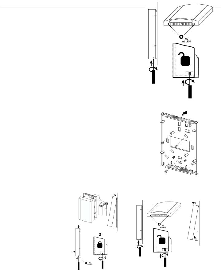
The cover is fastened to the base using Allen screws.
The cover is removed by inserting a #6 Allen tool into the two Allen fasteners found in the bottom of the case as shown, Figure 1.
Turn the screw clockwise (inward) until the case lifts easily. Remove the cover by lifting the front bottom outward.
To Install the Base
Note: If you are mounting the sensor to an existing electrical box, skip steps 1, 2 and 3. To prevent drafts from affecting the sensor reading, cover the openings in the back of
the case.
Figure 1
1. Place the case back on the surface of the wall area where the sensor is to be mounted and mark the location of at least three mounting holes.
2. Drill the marked holes and insert wall anchors into the surface.
3. Mount the back using at least three screws as shown in Figure 2.
4.Guide your facility wiring into the area of the case. Connect your wires to the probe wires that are part of the cover assembly using wire nuts, (see electrical connection section).
5.Collect any slack wire, fold and tuck into the case.
6.Fasten the cover to the mounted section. Hook the cover to the base as shown in Figure 3.
7.Turn the Allen screws counterclockwise (outward) until the cover is locked in place.
After Mounting: To Remove the Cover
Remove the cover from the case by inserting the tip of a small flat-head screwdriver Figure 2 into the two tab release areas in the bottom of the case as shown. Remove the cover by
lifting the front bottom outward.
Figure 4
FIGUre 3
Schneider Electric
2
<![if ! IE]><![endif]>© 2010 Schneider Electric. All rights reserved.
F-27577-1 |
June 2010 dl |

 Smart Sensor
Electrical Connection to TCX 866
The Smart Sensor module is powered by and accessed through an external TCX 866 VAV controller. The connection between the two uses three wires. These wires attach to an internal terminal block (Figure 7) located under the plastic cover of the TCX 866, Figure 6.
To access the terminal block and remove the cover, simply pull outward on the two opposite tabs that lock the cover to the base and pull upward.
Connect the Smart Sensor to the TCX 866 as shown in Figure 7.
The TCX 866 supplies power and communicates with the keypad and the display of the Smart Sensor over a single wire (the SPWR connection).
The RET line is the return for both the power supplied to the module and the internal thermistor.
The IN3 signal is the active lead from the thermistor. It connects to the IN3 Analog input to the TCX 866. Temperature readings from the Smart Sensor are read as Input 3.
The (Infinet -) and (Infinet +) wires provide access to the Infinet for the Lap-Top Service Tool connector on the bottom of the module.
Figure 7
Schneider Electric
Connection to the Smart Sensor is located behind this plastic cover.
Figure 5
Connection to the Smart
Sensor is made here.
Figure 6
<![endif]>© 2010 Schneider Electric. All rights reserved.
F-27577-1 |
June 2010 dl |
Smart Sensor |
4 |
|
|
|
|
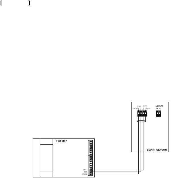
Electrical Connection to TCX 867 |
|
The interface between the TCX 867 and the Smart Sensor Bus consists of three wires connected to the following positions on the sixteen-terminal output connector located on the right side of the Controller module:
14RET
15IN3
16SPWR
The TEC 867 supplies power and communicates with the keypad and the display of the Smart Sensor device over a single wire (the SPWR connection).
The RET line is the return for both the power supplied to the module and the internal thermistor.
The IN3 signal is the active lead from the Smart Sensor thermistor. It connects to the IN3 input to the TCX 867. Temperature readings from the Smart Sensor are read as Input 3.
Figure 8 illustrates the connection between the two units.
Note: Input 3 is located on both the Input connector and on the 16-position Output connector. DO NOT USE the IN3 connection on the Input connector as a general temperature input when connecting the Smart Sensor.
Figure 8
<![if ! IE]><![endif]>© 2010 Schneider Electric. All rights reserved.
Schneider Electric
F-27577-1 |
June 2010 dl |
 Smart Sensor
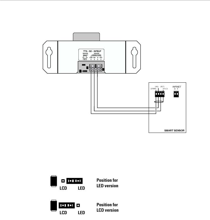
Electrical Connection to TTS-SD-INFBUF Board
1.Locate the interface wires from the Smart Sensor and route them to the Buffer Board.
2.Connect the wires as shown:
Figure 9
Position the Smart Sensor type jumper according to the version of sensor connected, Figure 10.
Figure 10
Schneider Electric
5
<![if ! IE]><![endif]>© 2010 Schneider Electric. All rights reserved.
F-27577-1 |
June 2010 dl |
Smart Sensor |
6 |
|
|
|
|
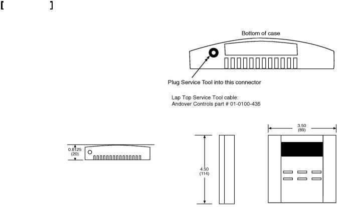
Lap Top Service Tool/Balance Tool Connection |
|
The Smart Sensor module includes an interface to the Andover Controls Lap-Top Service Tool and the Balance Tool.
Tool connection to the Smart Sensor requires a special adapter cable. This two wire shielded cable includes a special connector.
To connect the module to the Tool, follow Figure 11.
Figure 11
Dimensions
The Smart Sensor modules are designed to be mounted flush with a wall. The overall dimensions of the unit are as shown in Figure 12.
Figure 12
Operation
The Smart Sensor module requires connection to an external controller. After installation, the following tasks must be performed before you can use the Smart Sensor:
1.Create a set of appropriately named points for the Smart Sensor using the information in the Configuration Table provided in this section.
2.Connect the Smart Sensor module to the TCX 866, TCX 867 or to another Infinity controller using the TTS-SD-INFBUF interface.
3.Load and/or create Plain English programs in the controller to control and monitor the module. Information on reading from and writing to the Smart Sensor is included in the Programming section of this manual.
TCX 866/867 Configuration & Programming
TTS-SD-INFBUF Smart Sensor Buffer Board Notice
If you are using the TTS-SD-INFBUF Smart Sensor Buffer Board, do not use the information provided here. Refer to Appendix A for configuration information.
Configuration requires the creation of two types of points in your system.
Configuring the Thermistor
The thermistor is configured as any temperature device would be set up. Configure the TCX 866 or TCX 867 Input 3 (Analog Input) to be of Electrical Type: ACC_DEG_F or ACC_DEG_C. This sets up the input for reading temperature in degrees Fahrenheit or Celsius.
Important: Input 3 MUST be configured as a temperature input, otherwise, any operation of the Smart sensor (temperature or display) will not work!
Schneider Electric
<![endif]>© 2010 Schneider Electric. All rights reserved.
F-27577-1 |
June 2010 dl |

Smart Sensor |
7 |
|
Configuring the Keypad/Display
The keypad and display of the Smart Sensor are accessed by a single manual array. You configure their operation by creating a Numeric point.
The array for the TTS-SD-LCD model is called ‘LCDDisplay ‘(not case sensitive). The array for the TTS-SD-LED model is called ‘LEDDisplay ‘(not case sensitive).
This point must be set up as a manual array with 8 elements. The purpose of each element is listed below:
TTS-SD-LCD Array Elements:
LCDDisplay[0] |
Keypad Data. This element contains a number representing which key is pressed on the keypad. |
LCDDisplay[1] |
Data to be displayed in all formats except Segment. |
|
|
LCDDisplay[2] |
Format for display data |
|
|
LCDDisplay[3] |
Digit1 data in Segment mode. |
LCDDisplay[4} |
Digit2 data in Segment mode. |
|
|
LCDDisplay[5] |
Digit3 data in Segment mode. |
|
|
LCDDisplay[6] |
Digit 4 data in Segment mode. |
LCDDisplay[7} |
Control of display messages in all modes. |
|
|
TTS-SD-LED Array Elements:
LEDDisplay[0] |
Keypad Data. This element contains a number representing which key is pressed on the keypad. |
LEDDisplay[1] |
Data to be displayed in all formats except Segment. |
|
|
LEDDisplay[2] |
Format for display data. |
|
|
LEDDisplay[3] |
Digit1 data in Segment mode. |
LEDDisplay[4] |
Digit2 data in Segment mode. |
|
|
LEDDisplay[5] |
Not used. |
|
|
LEDDisplay[6] |
Not used. |
LEDDisplay[7} |
Control of decimal points in Segment mode. |
|
|
Once the temperature point and the array are configured you are free to enter values into the array to operate the Smart Sensor. Refer to the next section for specific programming information.
TTS-SD-INFBUF Smart Sensor Buffer Board Notice
This section applies to a Smart Sensor directly connected to a TCX 866 or TCX 867. If you are using the TTS-SD-INFBUF Smart Sensor Buffer Board with Infinity controllers that contain EMX ports (e.g., TCX-850, LCX-810, SCX-920), do not use the information provided here. Refer to Appendix A for programming information.
Once the temperature input point and the 8-element display array have been configured it is a relatively simple task to program the Smart Sensor for operation.
Reading temperature from the internal thermistor is a straightforward read of the input point.
Key presses on the six-button keypad are captured and placed into an array element automatically by the electronics within the module.
To visually display a value on the Smart Sensor, place the value into the element of the array and the module automatically extracts this data and formats it for display.
There are several display “modes” available. Set the display mode before presenting data for display. The following pages present these operations in more detail.
Schneider Electric
<![endif]>© 2010 Schneider Electric. All rights reserved.
F-27577-1 |
June 2010 dl |
 Loading...