


Schneider Electric TR3624 120 60, TR2412 120 60, TR1524 230 50, TR2424 120 60, TR2424 230 50 User Manual
...
Xantrex™ TR Series
Inverter/Charger
Xantrex TR1512 120 60 Xantrex TR3624 120 60
Xantrex TR1524 120 60 Xantrex TR1512 230 50
Xantrex TR2412 120 60 Xantrex TR1524 230 50
Xantrex TR2424 120 60 Xantrex TR2424 230 50
Operation Manual
www.schneider-electric.com


Xantrex TR Series
Inverter/Charger
Operation Manual
www.schneider-electric.com

Copyright and Contact
Trademarks
Schneider Electric, the Schneider Electric logo, and Xantrex are trademarks or registered trademarks of the
Schneider Electric group of companies. Other trademarks, registered trademarks, and product names are the
property of their respective owners and are used herein for identification purposes only.
Notice of Copyright
Copyright © 2008, 2009, 2010 Xantrex Technology I nc. All rights reserved. No part of this document may be
reproduced in any form or disclosed to third parties without the express written consent of:
Xantrex Technology Inc.
161-G South Vasco Road
Livermore, California USA 94551
Xantrex Technology Inc. reserves the right to revise this document and to periodically make changes to the
content hereof without obligation or organization of such revisions or changes unless required to do so by prior
arrangement.
Exclusion for Documentation
U
NLESS SPECIFICALLY AGREED TO IN WRITING, XANTREX TECHNOLOGY INC. (“XANTREX”)
(
A) MAKES NO WARRANTY AS TO THE ACCURACY, SUFFICIENCY OR SUITABILITY OF ANY TECHNICAL OR OTHER INFORMATION
PROVIDED IN ITS MANUALS OR OTHER DOCUMENTATION;
(
B) ASSUMES NO RESPONSIBILITY OR LIABILITY FOR LOSSES, DAMAGES, COSTS OR EXPENSES, WHETHER SPECIAL, DIRECT,
INDIRECT, CONSEQUENTIAL OR INCIDENTAL, WHICH MIGHT ARISE OUT OF THE USE OF SUCH INFORMATION. THE USE OF ANY
SUCH INFORMATION WILL BE ENTIRELY AT THE USER’S RISK; AND
(C) REMINDS YOU THAT IF THIS MANUAL IS IN ANY LANGUAGE OTHER THAN ENGLISH, ALTHOUGH STEPS HAVE BEEN TAKEN TO
MAINTAIN THE ACCURACY OF THE TRANSLATION, THE ACCURACY CANNOT BE GUARANTEED. APPROVED XANTREX CONTENT IS
CONTAINED WITH THE ENGLISH LANGUAGE VERSION WHICH IS POSTED AT WWW.SCHNEIDER-ELECTRIC.COM.
Date and Revision
March 2010 Revision C
Part Number
975-0391-01-01
Product Number
Xantrex TR1512 120 60, Xantrex TR2412 120 60, Xantrex TR1524 120 60, Xantrex TR2424 120 60, Xantrex
TR3624 120 60, Xantrex TR1512 230 50, Xantrex TR1524 230 50, Xantrex TR2424 230 50
Contact Information
www.schneider-electric.com
☎✉
North America 1 650 351 8237
1 866 519 1470
La France +0825012999 fr-re-techsupport@fr.schneider-electric.com
Deutschland +49 (0) 180 575 6575 +49 (0) 2102 404 7101 solarservice@de.schneider-electric.com
España +34 93 498 7466 +34 93 305 5026 re.techsupport@es.schneider-electric.com
L'Italia +39 035 4151111 +39 035415 3200 IT-pronto-contatto@it.schneider-electric.com
1 925 245 1022 re.techsupport@schneider-electric.com
For other country details please contact your local Schneider Electric Sales Representative or visit our website at:
http://www .schneider-electric.com/sites/corporate/en/support/operations/local-op erations/local-operations.page

About This Manual
Purpose
The purpose of this Operation Manual is to provid e explanat ions and pr ocedur es
for operating and troubleshooting the Schn e i de r Elec tr ic Xa n t rex TR Series
Inverter/Charger.
Scope
The Manual provides safety guidelines, and procedures for operating and
troubleshooting the inverter. It does not provide details about particular brands of
batteries. You need to consult individual battery manufacturers for this
information.
Audience
The Manual is intended for anyone who needs to operate or troubleshoot the
Xantrex TR Series Inverter/Charger. Installers must be certified technicians or
electricians.
Organization
This Manual is organized into three chapters and one appendix.
Chapter 1, “Introduction” co ntains information about the featur es and functions of
the Xantrex TR Series Inverter/Charger.
Chapter 2, “Operation” contains information about how to operate the Xantr ex TR
Series Inverter/Charger.
Chapter 3, “Troubleshooting” contains information about how to troubleshoot
possible error conditions while using the Xantrex TR Series Inverter/Charger.
Appendix A, “Specifications” contains information about the electrical,
environmental and regulatory specifications of the Xantrex TR Series Inverter/
Charger.
975-0391-01-01 iii
About This Manual
Conventions Used
Model Numbering
The following conventions are used in this guide.
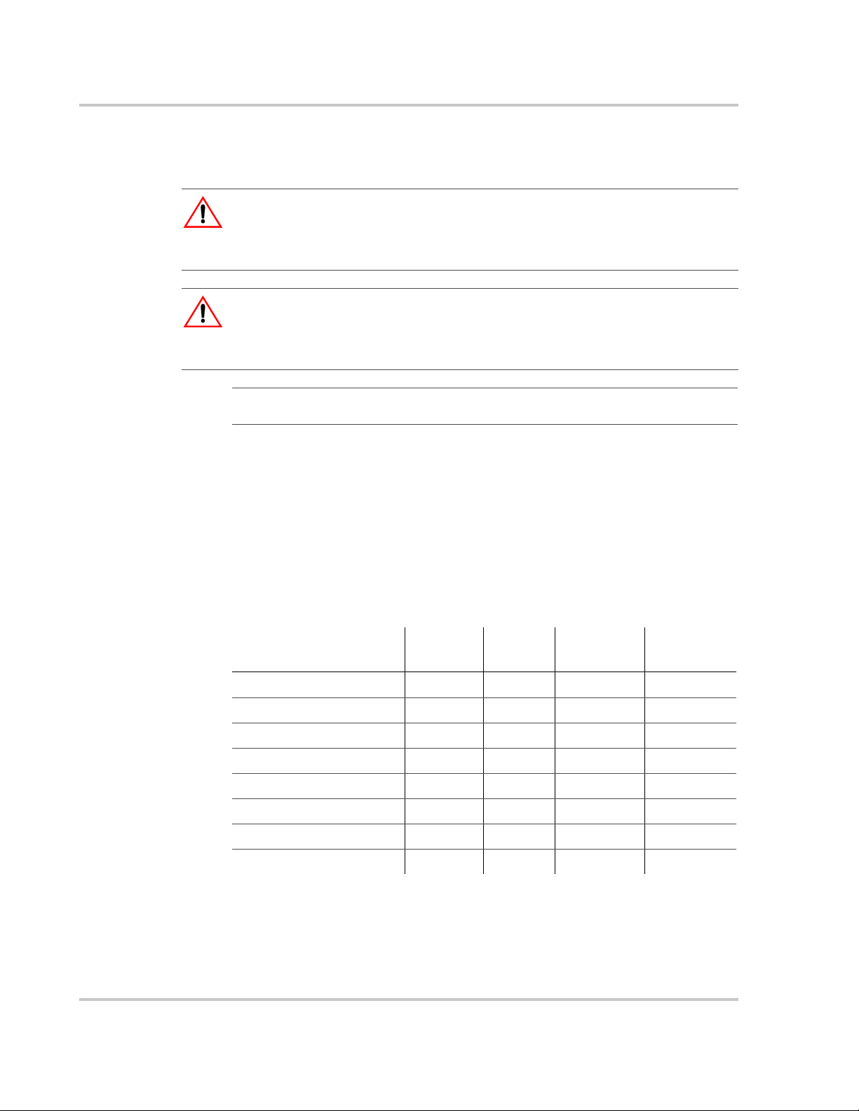
WARNING
Warnings identify conditions or practices that could result in personal injury or
loss of life
CAUTION
Cautions identify conditions or practices that could r esult in dama ge to the unit or
other equipment.
Important: These notes describe things which are important for you to know, but
not as serious as a caution or warning.
This Manual contains information for eight models of the Xantrex TR Series
Inverter/Charger.
Within this Manual, if information applies to all models of the Xantrex TR Series
Inverter/Charger then they will be referred to as the Xantrex TR Series. If
information only applies to select models then the model number will be
referenced as shown in the table belo w. Make sure you know which model
Xantrex TR Series Inverter/Charger you have purchased.
Input
Model Number
Xantrex TR1512 120 60 120 Vac 1500 VA 12 Volt 60 Hz
Xantrex TR2412 120 60 120 Vac 2400 VA 12 Volt 60 Hz
Xantrex TR1524 120 60 120 Vac 1500 VA 24 Volt 60 Hz
Xantrex TR2424 120 60 120 Vac 2400 VA 24 Volt 60 Hz
Xantrex TR3624 120 60 120 Vac 3600 VA 24 Volt 60 Hz
Xantrex TR1512 230 50 230 Vac 1500 VA 12 Volt 50 Hz
Xantrex TR1524 230 50 230 Vac 1500 VA 24 Volt 50 Hz
Xantrex TR2424 230 50 230 Vac 2400 VA 24 Volt 50 Hz
Voltage Power
Battery
Bank Size Frequency
iv 975-0391-01-01

Abbreviations and Acronyms
AC Alternating Current
ASC Authorized Service Center
COM Communications Port
DC Direct Current
PV Photovoltaic
RE Renewable Energy
RMA Return Material Authorization
Xantrex TR Series Xantrex TR Series Inverter/Charger
Related Information
You can find more information about Schneider Electric as well as its products
and services at www.schneider-electric.com.
About This Manual
975-0391-01-01 v

vi
IMPORTANT SAFETY INSTRUCTIONS
SAVE THESE INSTRUCTIONS
THIS MANUAL CONTAINS IMPORTANT
INSTRUCTIONS THAT SHALL BE FOLLOWED
DURING OPERATION OF ALL XANTREX TR
SERIES INVERTER/CHARGER MODELS.
WARNING: Limitations on use
The Xantrex TR Series is not intended for use in connection with life support
systems or other medical equipment or devices.
General
1. Before installing and using the Xantrex TR Series Inverter/Charger, read all
instructions and cautionary markings on the Xantrex TR Series Inverter/
Charger and all appropriate sections of this gu ide and the Xantrex TR Series
Inverter/Charger Installation Manual (Part #: 975-0367-01-01). Be sure to
read all instructions and cautionary markings for any equipment attach ed to
this unit.
2. This unit is designed for indoor use only. Do not expose the Xantrex TR
Series Inverter/Charger to rain, snow, or spray.
3. To reduce risk of fire hazard, do not cover or obstruct the ventilation
openings. Do not install the Xantrex TR Series Inverter/Charger in a zeroclearance compartment. Overheating may result.
4. Transformerless battery chargers are not to be used with this product family
due to the possible overheating and damage to the charger.
5. Use only attachments recommended or sold by the manufacturer. Doing
otherwise may result in a risk of fire, electric shock, or injury to persons.
6. To avoid a risk of fire and electric shock, make sure that existing wiring is in
good condition and that wire is not undersized. Do not operate the Xantrex
TR Series Inverter/Charger with damaged or substandard wiring.
975-0391-01-01 vii
Safety
7. Do not operate the Xantrex TR Series Inverter/Charger if it has received a
sharp blow, been dropped, or otherwise damaged in any way. If the Xantrex
TR Series Inverter/Charger is damaged, see the Warranty section.
8. Do not disassemble the Xantrex TR Series Inverter/Charger. It contains no
user-s erviceable parts. See Warranty for instructions on obtaining service.
Attempting to service the Xantrex TR Series Inverter/Charger yourself will
void your warranty and may result in a risk of electrical shock or fire. Internal
capacitors remain charged after all power is di sconnected.
9. The Xantrex TR Series contains more than one live circuit (batteries and AC
line). Power may be present at more than one source or from more than one
location. To reduce the risk of electrical shock, disconnect both AC and DC
power from the Xantrex TR Series Inverter/Charger before attempting any
maintenance or cleaning or working on any cir cuits conn ected to the Xant rex
TR Series Inverter/Charger. Turning off controls will not reduce this risk.
10. Use insulated tools to reduce the chance of short-circuits when installing or
working with the inverter, the batteries, or a PV array.
11. Several diagrams contained within this manual are basic in nature and are
included only to depict different installation options. All details may not be
shown, and as such, local electrical codes must still be referenced.
Explosive Gas Precautions
WARNING: Explosion Hazard
Working in the vicinity of lead-acid batteries is dangerous. Batteries generate
explosive gases during normal operation. Therefore, you must read this guide
and follow the instructions exactly before installing or using your Xantrex TR
Series Inverter/Charger.
1. This equipment contains components which tend to produce arcs or sparks.
To prevent fire or explosion, do not install the Xantrex TR Series Inverter/
Charger in compartments containing batteries or flammable mater ials, or in
locations that requir e ignition-protected equipment. This includes any space
containing gasoline-powered machinery, fuel tanks, as well as joints, fittings,
or other connections between components of the fuel system.
2. To reduce the risk of battery explosion, follow these instructions and those
published by the battery manufacturer and the manufacturer of the
equipment in which the battery is installed.
viii 975-0391-01-01

Precautions When Working With Batteries
WARNING: Explosion or Fire Hazard
Follow all instructions published by the battery manufacturer an d the
manufacturer of the equipment in which the battery is installed.
1. Make sure the area around the battery is well ventilated.
2. Never smoke or allow a spark or flame near the engine or batteries.
3. Use caution to reduce the risk or dr opping a metal tool on th e battery. It could
spark or short circuit the battery or other electrical pa rts and could cause a n
explosion.
4. Remove all metal items, like rings, bracelets, and watches when working with
lead-acid batteries. Lead-acid batteries produce a short circuit current high
enough to weld metal to skin, causing a severe burn.
5. Have someone within range of your voice or close enough to come to your
aid when you work near a lead-acid battery.
6. Have plenty of fresh water and soap nearby in case battery acid contacts
skin, clothing, or eyes.
7. Wear complete eye protection and clothing protection. Avoid touching your
eyes while working near batteries.
8. If battery acid contacts skin or clothing, wash immediately with soap and
water. If acid enters your eye, immediately flood it with running cold water for
at least twenty minutes and get medical attention immediately.
9. If you need to remove a battery, always remove the grounded terminal from
the battery first. Make sure all ac cessories ar e of f so you don’ t cau se a sp ark.
10. Always use identical types of batteries.
11. Never install old or untested batteries. Check each battery’s date code or
label to ensure age and type.
12. Batteries are temperature sensitive. For optimum performance, they should
be installed in a stable temperature environment.
13. Always recycle old batteries. Contact your local recycling center for proper
disposal information.
Safety
975-0391-01-01 ix

Regulatory
The Xantrex TR Series Inverter/Charger 120 Vac/60 Hz models are CSA
Certified to appropriate US and Canadian standards. The 230 Vac/50 Hz
models have been marked with the CE designation for Europ ean countries. S ee
“Safety and Electromagnetic Compatibility Specifications” on page A–5 for
more detailed information.
The Xantrex TR Series Inverter/Charger is int ended to be used for residential or
commercial applications. Do NOT use this unit for applications for which it is not
listed (for example, land vehicles or marine craft). It may not comply with the
safety code requireme nts or could possibly present other operational or safety
hazards.
FCC
Information
for the User
The Xantrex TR Series Inverter/Charger has been tested and found to comply
with the limits for a Class B digital device, pursuant to part 15 of the FCC Rules.
These limits are designed to provide reasonable protection against harmful
interference when the equipment is operated in a residential environment. This
equipment generates, uses and can radiate radio frequency energy and, if not
installed and used in accordance with this Operation Manual, may cause
harmful interference to radio communications. However, there is no guarantee
that interference will not occur in a particular installation. If this equipment does
cause harmful interference to radio or television reception, which can be
determined by turning the equipment on and off, the user is encouraged to try
to correct the interference by one or more of the following measures:
• Reorient or relocate the receiving antenna
• Increase the separation between the equipment and the receiver
• Connect the equipment into a cir cuit differ ent fr om that which th e receiver is
connected
• Consult the dealer where the eq uipment was purchased or an experienced
radio/ TV technician for help
x

Contents
IMPORTANT SAFETY INSTRUCTIONS
- - - - - - - - - - - - - - - - - - - - - - - - - - - - -vii
1 Introduction
Introduction - - - - - - - - - - - - - - - - - - - - - - - - - - - - - - - - - - - - - - - - - - - - - - - - - - - - - - - - - - - - - 1–2
Features - - - - - - - - - - - - - - - - - - - - - - - - - - - - - - - - - - - - - - - - - - - - - - - - - - - - - - - - - - - - - - - 1–3
AC Side - - - - - - - - - - - - - - - - - - - - - - - - - - - - - - - - - - - - - - - - - - - - - - - - - - - - - - - - - - - - - 1–4
DC Side - - - - - - - - - - - - - - - - - - - - - - - - - - - - - - - - - - - - - - - - - - - - - - - - - - - - - - - - - - - - - 1–5
Optional Equipment - - - - - - - - - - - - - - - - - - - - - - - - - - - - - - - - - - - - - - - - - - - - - - - - - - - - 1–5
Remote on/off Switch - - - - - - - - - - - - - - - - - - - - - - - - - - - - - - - - - - - - - - - - - - - - - - - - - 1–5
DC Conduit Box - - - - - - - - - - - - - - - - - - - - - - - - - - - - - - - - - - - - - - - - - - - - - - - - - - - - 1–5
2 Operation
Front Panel- - - - - - - - - - - - - - - - - - - - - - - - - - - - - - - - - - - - - - - - - - - - - - - - - - - - - - - - - - - - - - 2–2
User Interface - - - - - - - - - - - - - - - - - - - - - - - - - - - - - - - - - - - - - - - - - - - - - - - - - - - - - - - - - 2–2
Service Control Interface - - - - - - - - - - - - - - - - - - - - - - - - - - - - - - - - - - - - - - - - - - - - - - - - - 2–5
Over Discharge Protection (ODP) - - - - - - - - - - - - - - - - - - - - - - - - - - - - - - - - - - - - - - - - 2–8
Setting the Search Mode Threshold - - - - - - - - - - - - - - - - - - - - - - - - - - - - - - - - - - - - - - 2–9
Stacking Interface - - - - - - - - - - - - - - - - - - - - - - - - - - - - - - - - - - - - - - - - - - - - - - - - - - 2–10
Remote Control - - - - - - - - - - - - - - - - - - - - - - - - - - - - - - - - - - - - - - - - - - - - - - - - - - - - 2–10
Start-up - - - - - - - - - - - - - - - - - - - - - - - - - - - - - - - - - - - - - - - - - - - - - - - - - - - - - - - - - - - - - - - 2–11
Charge Mode- - - - - - - - - - - - - - - - - - - - - - - - - - - - - - - - - - - - - - - - - - - - - - - - - - - - - - - - - - - 2–12
3-Stage Charging Process - - - - - - - - - - - - - - - - - - - - - - - - - - - - - - - - - - - - - - - - - - - - - - - 2–12
Standby Mode - - - - - - - - - - - - - - - - - - - - - - - - - - - - - - - - - - - - - - - - - - - - - - - - - - - - - - - 2–13
OFF Mode - - - - - - - - - - - - - - - - - - - - - - - - - - - - - - - - - - - - - - - - - - - - - - - - - - - - - - - - - - 2–13
Equalize Charging - - - - - - - - - - - - - - - - - - - - - - - - - - - - - - - - - - - - - - - - - - - - - - - - - - - - 2–13
3 Troubleshooting
Troubleshooting the Xantrex TR Series - - - - - - - - - - - - - - - - - - - - - - - - - - - - - - - - - - - - - - - - - - 3–2
Problem Loads- - - - - - - - - - - - - - - - - - - - - - - - - - - - - - - - - - - - - - - - - - - - - - - - - - - - - - - - - - - 3–8
A Specifications
Safety and Electromagnetic Compatibility Specifications - - - - - - - - - - - - - - - - - - - - - - - - - - A–5
Warranty and Return Information
975-0391-01-01 xi
- - - - - - - - - - - - - - - - - - - - - - - - - - - - - - - - - - - - - - - - WA–1

xii

Figures
Figure 1-1 Front Panel Features - - - - - - - - - - - - - - - - - - - - - - - - - - - - - - - - - - - - - - - - - - - - - - - - 1–3
Figure 1-2 AC Side of the Xantrex TR Series - - - - - - - - - - - - - - - - - - - - - - - - - - - - - - - - - - - - - - - 1–4
Figure 1-3 DC Side of the Xantrex TR Series - - - - - - - - - - - - - - - - - - - - - - - - - - - - - - - - - - - - - - - 1–5
Figure 2-1 Front Panel User Interface - - - - - - - - - - - - - - - - - - - - - - - - - - - - - - - - - - - - - - - - - - - - 2–2
Figure 2-2 Removing the Service Access Cover- - - - - - - - - - - - - - - - - - - - - - - - - - - - - - - - - - - - - 2–5
Figure 2-3 Front Panel Control Interface - - - - - - - - - - - - - - - - - - - - - - - - - - - - - - - - - - - - - - - - - - 2–6
Figure 2-4 Automatically Calculated Discharge Cutoff Voltage per Cell - - - - - - - - - - - - - - - - - - - - 2–8
Figure 2-5 Search Mode Potentiometer Adjustment - - - - - - - - - - - - - - - - - - - - - - - - - - - - - - - - - 2–10
975-0391-01-01 xiii

xiv

Tables
Table 1-1 Supplemental Circuit Breaker Sizing - - - - - - - - - - - - - - - - - - - - - - - - - - - - - - - - - - - - - 1–4
Table 2-1 Battery Charge Profiles - - - - - - - - - - - - - - - - - - - - - - - - - - - - - - - - - - - - - - - - - - - - - - 2–7
Table 3-1 Error Codes- - - - - - - - - - - - - - - - - - - - - - - - - - - - - - - - - - - - - - - - - - - - - - - - - - - - - - - 3–2
Table 3-2 Troubleshooting the Xantrex TR Series - - - - - - - - - - - - - - - - - - - - - - - - - - - - - - - - - - - 3–6
Table A-1 Electrical Specifications - 120 Vac/60 Hz Models - - - - - - - - - - - - - - - - - - - - - - - - - - - - A–2
Table A-2 Electrical Specifications - 230 Vac/50 Hz Models - - - - - - - - - - - - - - - - - - - - - - - - - - - - A–4
Table A-3 Environmental Specifications - - - - - - - - - - - - - - - - - - - - - - - - - - - - - - - - - - - - - - - - - - A–5
975-0391-01-01 xv

xvi
 Loading...