


Schneider Electric TAC Xenta 400 Users Manual

<![endif]>TAC Xenta©
TAC Xenta® 400 I/O Modules

<![endif]>TAC Xenta©
TAC Xenta® 400 I/O Modules
Copyright © 2003 TAC AB. All rights reserved.
This document, as well as the product it refers to, is only intended for licensed users. TAC AB owns the copyright of this document and reserves the right to make changes, additions or deletions. TAC AB assumes no responsibility for possible mistakes or errors that might appear in this document.
Do not use the product for other purposes than those indicated in this document.
Only licensed users of the product and the document are permitted to use the document or any information therein. Distribution, disclosure, copying, storing or use of the product, the information or the illustrations in the document on the part of non-licensed users, in electronic or mechanical form, as a recording or by other means, including photo copying or information storage and retrieval systems, without the express written permission of TAC AB, will be regarded as a violation of copyright laws and is strictly prohibited.
Trademarks and registered trademarks are the property of their respective owners. Microsoft® and Windows® are registered trademarks of The Microsoft Corporation.
Trademarks and registered trademarks are the property of their respective owners.
TAC Vista®, TAC Menta®, TAC Xenta® and TAC I-talk® are registered trademarks of TAC AB.

TAC Xenta, TAC Xenta® 400 I/O Modules |
Contents |
|
|
Contents
INTRODUCTION
1 Introduction |
9 |
|
1.1 |
Structure ..................................................................................................................... |
9 |
1.2 |
Terminology............................................................................................................... |
9 |
1.3 |
New in this Edition..................................................................................................... |
9 |
1.4 |
Typographic Conventions .......................................................................................... |
10 |
1.5 |
More information ....................................................................................................... |
10 |
REFERENCE
2 I/O Modules in the TAC Xenta 400 series |
13 |
||
|
2.1 |
Hardware Units .......................................................................................................... |
13 |
|
2.2 |
Configurations............................................................................................................ |
15 |
3 |
Technical Description |
17 |
|
|
3.1 |
Common Features ...................................................................................................... |
17 |
|
3.1.1 |
Terminals.................................................................................................................... |
17 |
|
3.1.2 |
Indicators and Service pin.......................................................................................... |
17 |
|
3.1.3 |
Technical data, common to all ................................................................................... |
18 |
|
3.2 |
TAC Xenta 411/412 Digital Input module................................................................. |
19 |
|
3.3 |
TAC Xenta 421/422 Digital Input and Output module.............................................. |
20 |
|
3.4 |
TAC Xenta 421A/422A Universal Input and Digital Output module ....................... |
22 |
|
3.5 |
TAC Xenta 451/452 Analog Input and Output module ............................................. |
24 |
|
3.6 |
TAC Xenta 451A/452A Universal Input and Analog Output module....................... |
26 |
|
3.7 |
TAC Xenta 471 Analog Input module ....................................................................... |
29 |
|
3.8 |
TAC Xenta 491/492 Analog Output module ............................................................. |
31 |
4 |
Installation |
33 |
|
|
4.1 |
Mounting .................................................................................................................... |
33 |
|
4.2 |
Electrical installation.................................................................................................. |
34 |
|
4.2.1 |
General considerations ............................................................................................... |
34 |
|
4.2.2 |
Input/Output Circuit Principles .................................................................................. |
34 |
|
4.2.3 |
Terminals and units .................................................................................................... |
38 |
|
4.2.4 |
Cables......................................................................................................................... |
42 |
|
4.3 |
Commissioning .......................................................................................................... |
44 |
Index |
|
45 |
|
TAC AB, Dec 2004 |
5 (48) |
0-004-7771-3 (EN) |
|

Contents |
TAC Xenta, TAC Xenta® 400 I/O Modules |
|
|
6 (48) |
TAC AB, Dec 2004 |
|
0-004-7771-3 (EN) |
INTRODUCTION
1 Introduction

TAC Xenta, TAC Xenta® 400 I/O Modules |
1 Introduction |
|
|
1 Introduction
The TAC Xenta 400 is a series of input/output modules designed to be connected to the TAC Xenta 300 or 401 type controllers.
The installation procedures and technical data are similar between the different modules.
For information on how to install software, we refer to the instructions delivered with the software.
1.1Structure
The manual is divided into the following parts:
•Introduction
The Introduction section contains information on how this manual is structured and where to find additional information.
•Reference
The Reference section contains comprehensive information about the products. It also provides you with information on mounting and electrical installation.
1.2Terminology
Term |
Description |
|
|
|
|
ASIC |
Application Specific Integrated Circuit |
|
|
1.3New in this Edition
In this edition the new ASIC-based modules TAC Xenta 421A/422A and TAC Xenta 451A/452A have been added, mainly in chapter 3.
TAC AB, Dec 2004 |
9 (48) |
0-004-7771-3 (EN) |
|
1 Introduction |
TAC Xenta, TAC Xenta® 400 I/O Modules |
|
|
1.4Typographic Conventions
Throughout the manual four specially marked texts may occur.
Warning
Used to emphasize operations that can cause serious personal injury or damage to property if not handled correctly.
Caution
Used to emphasize operations that can cause serious problems if not handled correctly.
Note
Used to emphasize certain information.
Hint
Used to emphasize processes that may ease operation.
1.5More information
The TAC Xenta 400 I/O modules and the other TAC Xenta units are also described in the following documents:
•the “TAC Xenta 280/300/401 Handbook”, part no. 0-004-7768
•the “TAC Xenta OP Handbook”, part no. 0-004-7506
•the “Engineering Classic Networks”, part no. 0-004-7841
•the “Endangering LNS Networks”, part no. 0-004-7842
•the “Engineering Applications in TAC Menta”, part no. 0-004-7843 (to be replaced by 0-004-7896)
•data sheets for the TAC Xenta 4xx range (C-92-nn)
•the TAC Xenta OP Operator panel data sheet (C-98-05)
•a brief installation instruction, “0FL”, included at delivery
10 (48) |
TAC AB, Dec 2004 |
|
0-004-7771-3 (EN) |
REFERENCE
2I/O Modules in the TAC Xenta 400 series
3Technical Description
4Installation
TAC Xenta, TAC Xenta® 400 I/O Modules |
2 I/O Modules in the TAC Xenta 400 series |
|
|
2I/O Modules in the TAC Xenta 400 series
2.1Hardware Units
Warning
The TAC Xenta 400 I/O modules and the other products of the TAC Xenta family must not be used for any other purpose than those for which they were designed.
Installation, connection and repair may only be performed by authorized personnel.
The TAC Xenta freely-programmable controllers consist of the following units.
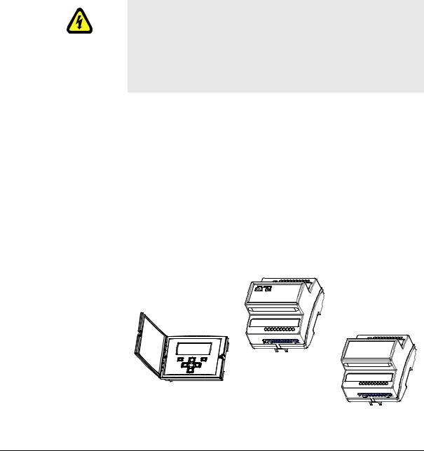
•The TAC Xenta 301/302/401 controller. The controller is the brain of the system. It contains the database of the inputs and outputs of the plant. It also contains the system and application software for all the functions that are to be performed by the controller and connected peripheral units.
•I/O expansion modules, which provide the inputs and outputs of the TAC Xenta controller.
•The TAC Xenta OP is an easy-to-use operator panel, with a display. The values are presented in plain language in a menu system. The OP can be connected to any controller in the network.
TAC Xenta controller
12 13 14 15 16 17 18 20
20
Operator panel |
TAC Xenta 400 |
|
Input/Output module |


 12 13 14 15 16 17 18
 20
20
Fig. 2.1: TAC Xenta units; the Operator panel, the TAC Xenta controller (here: 401) and an I/O expansion module
TAC AB, Dec 2004 |
13 (48) |
0-004-7771-3 (EN) |
|

2 I/O Modules in the TAC Xenta 400 series |
|
|
TAC Xenta, TAC Xenta® 400 I/O Modules |
||||||||
|
|
|
|
|
|
|
|
|
|
||
|
|
A number of controllers and I/O modules can form a local network and |
|||||||||
|
|
exchange data. |
|
|
|
|
|
|
|
||
|
|
The TAC Xenta OP operator panel is used to give the user access to cer- |
|||||||||
|
|
tain parameters and make it possible to present alarms without commu- |
|||||||||
|
|
nicating with a central system. The most important functions of the |
|||||||||
|
|
operator panel are status monitoring, adjustment of setpoints and time |
|||||||||
|
|
channels and the display of alarms. |
|
|
|
||||||
|
|
A maximum of two OPs may be connected to each controller. |
|||||||||
|
|
The I/O modules are used as expansion modules for the TAC Xenta |
|||||||||
|
|
controllers, connected to these via the common TP/FT-10 network. |
|||||||||
|
|
The modules have different I/O configurations to suit different applica- |
|||||||||
|
|
tions. Some models have indicators for the digital input status and a |
|||||||||
|
|
manual override for the digital or analog outputs. An overview of the |
|||||||||
|
|
available models is shown below. |
|
|
|
||||||
Table 2.1: Available I/O modules and their I/O configuration |
|
|
|
|
|
||||||
|
|
|
|
|
|
|
|
|
|
|
|
|
I/O Module |
DI |
DI |
|
DO |
DO |
|
UI |
TI |
AO |
AO |
|
TAC |
status |
|
override |
|
override |
|||||
|
|
|
|
|
|
|
|
|
|
|
|
|
|
|
|
|
|
|
|
|
|
|
|
|
Xenta 411 |
10 |
- |
|
- |
- |
|
- |
- |
- |
- |
|
|
|
|
|
|
|
|
|
|
|
|
|
Xenta 412 |
10 |
10 |
|
- |
- |
|
- |
- |
- |
- |
|
|
|
|
|
|
|
|
|
|
|
|
|
Xenta 421 |
4 |
- |
|
5 |
- |
|
- |
- |
- |
- |
|
|
|
|
|
|
|
|
|
|
|
|
|
Xenta 422 |
4 |
4 |
|
5 |
5 |
|
- |
- |
- |
- |
|
|
|
|
|
|
|
|
|
|
|
|
|
Xenta 421A |
- |
- |
|
5 |
- |
|
4a |
- |
- |
- |
|
Xenta 422A |
- |
4b |
|
5 |
5 |
|
4a |
- |
- |
- |
|
Xenta 451 |
- |
- |
|
- |
- |
|
4c |
4 |
2 |
- |
|
Xenta 452 |
- |
4b |
|
- |
- |
|
4c |
4 |
2 |
2 |
|
Xenta 451A |
- |
- |
|
- |
- |
|
8a |
- |
2 |
- |
|
Xenta 452A |
- |
8b |
|
- |
- |
|
8a |
- |
2 |
2 |
|
Xenta 471 |
- |
- |
|
- |
- |
|
8d |
- |
- |
- |
|
Xenta 491 |
- |
- |
|
- |
- |
|
- |
- |
8 |
- |
|
|
|
|
|
|
|
|
|
|
|
|
|
Xenta 492 |
- |
- |
|
- |
- |
|
- |
- |
8 |
8 |
|
|
|
|
|
|
|
|
|
|
|
|
a.DI, 0–10 V DC or 0–20 mA, 1.8/10 kohm TI
b.Status indication only when the corresponding universal inputs (UI) are being used as digital inputs.
c.DI, 0–10 V DC, 1.8 kohm TI
d.0–10 V DC or 0–20 mA
14 (48) |
TAC AB, Dec 2004 |
|
0-004-7771-3 (EN) |
TAC Xenta, TAC Xenta® 400 I/O Modules |
2 I/O Modules in the TAC Xenta 400 series |
|
|
where
DI: Digital input DO:Digital output UI: Universal input TI: Thermistor input AO:Analog output
2.2Configurations
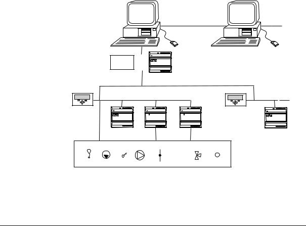
The I/O modules of the TAC Xenta 400 series can be used in different configurations, for example:
•Together with a stand-alone controller.
•With controllers and OPs in a network.
•Controllers, OPs, I/O modules and other equipment in a full network with suitable adapters, possibly connected to a TAC Vista Central System.
For further information, please consult the “Engineering Network” guides.
TAC |
|
TAC |
|
Vista |
|
Vista |
|
Management |
|
|
|
level |
|
|
|
PCLTA |
or |
|
|
card |
|
|
|
|
|
|
|
|
TAC Xenta 901 |
|
|
Automation |
|
TP/FT-10 |
|
level |
|
|
|
TAC Xenta OP |
|
|
TAC Xenta OP |
TAC Xenta 401 |
I/O- module |
I/O- module |
TAC Xenta 401 |
Field |
+ |
- |
|
level |
|
||
Fig. 2.2: An example of a TAC Xenta network
TAC AB, Dec 2004 |
15 (48) |
0-004-7771-3 (EN) |
|
 Loading...