Schneider Electric TAC Xenta 471 Installation Instructions

|
|
|
|
|
TAC Xenta 471 |
02-00036-01-en |
|
|
|
|
|
|
|
|
|
|
|
|
Analog ingångsmodul |
Installationsanvisning |
|
|
|
||||
|
|
|
||||
|
|
|
|
|
Analog Input module |
Installation instruction |
|
|
|
|
|||
|
|
|
|
|
Analogeingangsmodul |
Installationsanleitung |
|
|
|
|
|
|
|
1 |
2 |
|
|
|
|
|
12 13 14 15 |
16 |
17 |
18 |
20 |
TAC Xenta 471
24 V AC |
Comm |
|
|
|
|
|||
(19-40 V DC) |
<![if ! IE]> <![endif]>} |
|
|
|
|
|
||
| <![if ! IE]> <![endif]>} |
|
|
|
|
|
|||
~ |
0 |
|
|
|
<![if ! IE]> <![endif]>24 V DC |
M U2 U324VDC |
||
G G0C1C2 U1 |
||||||||
1 |
2 |
3 |
4 |
5 |
6 |
7 |
8 |
9 10 |
11 12 13 14 15 16 17 18 19 20
| <![if ! IE]> <![endif]>V24DC |
M U6 U7 |
<![if ! IE]> <![endif]>V24DC |
M U8 |
M U4 U5 |
|
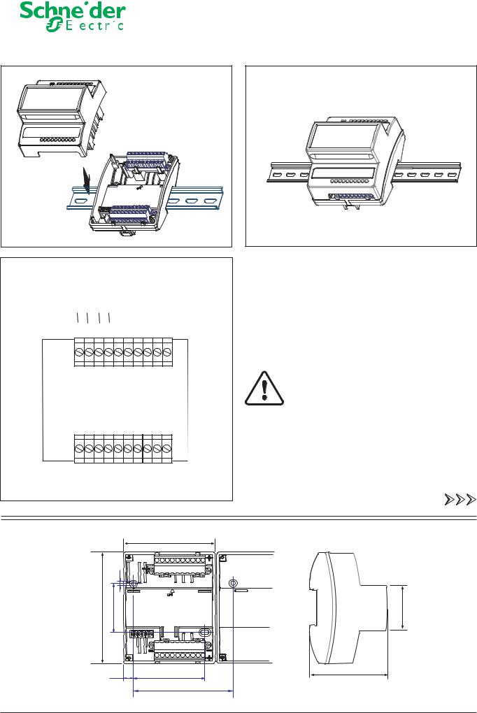
Observera! Figuren visar endast generella inkopplingar. För detaljer, se dokumentationen till de specifika applikationerna.
Note! The figure only shows connections in general. For further details, please refer to the documentation on the specific applications.
Anmerkung! Die Abbildung zeigt lediglich die allgemeine Klemmenbelegung. Weitere Einzelheiten gehen aus der Dokumentation der Anwendung hervor.
(mm:) |
|
|
90 |
|
|
|
|
|
|
|
|
2 |
3 |
4 |
5 |
6 |
7 |
8 |
10 |
|
4 |
|
|
|
|
|
|
|
|
| <![if ! IE]> <![endif]>110 |
<![if ! IE]> <![endif]>48 – 0,5 |
|
|
|
|
|
|
|
<![if ! IE]> <![endif]>45 |
|
|
12 13 |
14 15 16 |
17 |
18 |
20 |
|||
|
10,1 |
70 – 2,0 |
|
|
77,4 |
||||
|
|
|
|
||||||
|
|
90 + 0,4 to the next module |
|||||||
02-00036-01-en, Nov 2009 |
|
|
|
|
|
|
|
|
Svenska - English - Deutsch 1 (2) |

Blocktyper i TAC Menta |
Plintbeteckn. |
In/utg.-slag |
Block types in TAC Menta |
Terminal ref. |
Type of I/O |
Blocktypen in TAC Menta |
Klemmenbez. |
E/A-Typ |
|
|
|
AI - Analoga ingångar |
U1 - U8 |
Analoga ingångar |
AI - Analog inputs |
U1 - U8 |
Analog inputs |
AI - Analogeingänge |
U1 - U8 |
Analogeingänge |
|
|
|
TAC Xenta 471
Servicebrytare:
Service pin:
Servicetaste:
LED: röd ind. = hårdvarufel el. okonfigurerad nod
LED: red light = hw fault or unconfigured node
LED: rot = Hardwarefehler oder
Knoten nicht konfiguriert
LED: grönt blinkande ljus, ~1 Hz = fungerande kommunikation
LED: green blinking light, ~1 Hz = communication running
LED: grün blinkend, ~1 Hz =
Kommunikation aktiv
|
|
|
|
|
|
|
|
|
|
|
|
|
|
|
|
|
|
|
|
2 (2) Svenska - English - Deutsch |
|
|
02-00036-01-en, Nov 2009 |
|
 Loading...