


Schneider Electric TAC Xenta 500, TAC Xenta 700, TAC Xenta 911, TAC Xenta 913 Users Manual
TAC Vista
TAC Pangaea
WorkStation
TAC Xenta 500/700/911/913
Product Manual

TAC Vista
TAC Xenta 500/700/911/913
Product Manual
Copyright © 2011 Schneider Electric Buildings AB. All rights reserved.
This document, as well as the product it refers to, is only intended for licensed users. Schneider Electric Buildings AB owns the copyright of this document and reserves the right to make changes, additions or deletions. Schneider Electric Buildings AB assumes no responsibility for possible mistakes or errors that might appear in this document.
Do not use the product for other purposes than those indicated in this document.
Only licensed users of the product and the document are permitted to use the document or any information therein. Distribution, disclosure, copying, storing or use of the product, the information or the illustrations in the document on the part of non-licensed users, in electronic or mechanical form, as a recording or by other means, including photo copying or information storage and retrieval systems, without the express written permission of Schneider Electric Buildings AB, will be regarded as a violation of copyright laws and is strictly prohibited.
Trademarks and registered trademarks are the property of their respective owners.

TAC Xenta 500/700/911/913, Product Manual |
Contents |
|
|
Contents
INTRODUCTION
1 About this Manual |
11 |
|
1.1 |
Structure ..................................................................................................................... |
12 |
1.2 |
Typographic Conventions .......................................................................................... |
12 |
1.3 |
Terminology............................................................................................................... |
13 |
1.4 |
Related Documents .................................................................................................... |
14 |
REFERENCE
2 TAC Xenta 500/700/911/913 |
17 |
|
2.1 |
Hardware .................................................................................................................... |
17 |
2.1.1 |
Communication Interface........................................................................................... |
18 |
2.1.2 |
Port Pins ..................................................................................................................... |
21 |
2.1.3 |
Fail-Safe State ............................................................................................................ |
23 |
2.1.4 |
LEDs .......................................................................................................................... |
23 |
2.2 |
Configuring the TAC Xenta 500/700/911/913 .......................................................... |
25 |
2.2.1 |
Configuration Data..................................................................................................... |
25 |
2.2.2 |
Configuring Windows HyperTerminal ...................................................................... |
26 |
2.2.3 |
Configuring the TAC Xenta....................................................................................... |
28 |
2.3 |
Verifying the TAC Xenta Communication ................................................................ |
31 |
2.3.1 |
Accessing the TAC Xenta.......................................................................................... |
32 |
2.3.2 |
Changing the Root Password ..................................................................................... |
34 |
2.4 |
Temporary Login ID .................................................................................................. |
35 |
2.5 |
Upgrading the System Program ................................................................................. |
36 |
3 Connecting the TAC Xenta to Your Network |
41 |
|
3.1 |
Alternative Port Settings ............................................................................................ |
42 |
3.1.1 |
HTTP and HTTPS...................................................................................................... |
42 |
4 TAC Xenta 511 |
43 |
|
4.1 |
Configuration Phase ................................................................................................... |
43 |
4.1.1 |
Connections, configuration ........................................................................................ |
44 |
4.2 |
Engineering Phase...................................................................................................... |
45 |
4.2.1 |
Connections, engineering........................................................................................... |
46 |
4.3 |
Operating Phase ......................................................................................................... |
47 |
4.3.1 |
Directly Connected..................................................................................................... |
47 |
4.3.2 |
Connections, operation directly ................................................................................. |
48 |
4.3.3 |
Dialed-Up, operation.................................................................................................. |
49 |
4.3.4 |
Connections................................................................................................................ |
, op- |
|
eration dial-up ............................................................................................................ |
50 |
Schneider Electric Buildings AB, Feb 2011 |
5 (134) |
04-00071-04-en |
|

Contents |
TAC Xenta 500/700/911/913, Product Manual |
||
|
|
|
|
|
4.4 |
Port Usage .................................................................................................................. |
51 |
5 |
TAC Xenta 527 |
53 |
|
|
5.1 |
Configuration Phase ................................................................................................... |
53 |
|
5.1.1 |
Connections ................................................................................................................ |
54 |
|
5.2 |
Engineering Phase ...................................................................................................... |
55 |
|
5.2.1 |
Connections ................................................................................................................ |
56 |
|
5.3 |
Operating Phase.......................................................................................................... |
58 |
|
5.3.1 |
Directly Connected..................................................................................................... |
58 |
|
5.3.2 |
Connections ................................................................................................................ |
58 |
|
5.3.3 |
Dialed-Up ................................................................................................................... |
60 |
|
5.3.4 |
Connections ................................................................................................................ |
60 |
|
5.4 |
Port Usage .................................................................................................................. |
63 |
|
5.5 |
Connecting the TAC Xenta 527 to an I/NET Controller LAN .................................. |
64 |
|
5.6 |
Using a Direct Connection to I/NET .......................................................................... |
65 |
6 |
TAC Xenta 555 |
67 |
|
|
6.1 |
Configuration Phase ................................................................................................... |
67 |
|
6.1.1 |
Connections ................................................................................................................ |
68 |
|
6.2 |
Engineering Phase ...................................................................................................... |
69 |
|
6.2.1 |
Connections ................................................................................................................ |
70 |
|
6.2.2 |
RS485 LAN Wiring.................................................................................................... |
72 |
|
6.3 |
Operating Phase.......................................................................................................... |
73 |
|
6.3.1 |
Connections ................................................................................................................ |
73 |
|
6.4 |
Port Usage .................................................................................................................. |
75 |
|
6.5 |
Connecting the TAC Xenta 555 to a MicroNet Controller LAN ............................... |
76 |
|
6.5.1 |
Connecting to a MicroNet NCP network (MN MI not used)..................................... |
77 |
|
6.5.2 |
Connecting to a MicroNet ARCNET network (MN MI used)................................... |
78 |
|
6.5.3 |
Connecting to a Satchnet network (MIU not used) .................................................... |
78 |
7 |
TAC Xenta 701/711/721 |
79 |
|
|
7.1 |
Configuration Phase ................................................................................................... |
79 |
|
7.1.1 |
Connections ................................................................................................................ |
80 |
|
7.2 |
Engineering Phase ...................................................................................................... |
81 |
|
7.2.1 |
Connections ................................................................................................................ |
82 |
|
7.3 |
Operating Phase.......................................................................................................... |
83 |
|
7.3.1 |
Directly Connected..................................................................................................... |
83 |
|
7.3.2 |
Connections ................................................................................................................ |
84 |
|
7.3.3 |
Dialed-Up ................................................................................................................... |
85 |
|
7.3.4 |
Connections ................................................................................................................ |
86 |
|
7.4 |
Port Usage .................................................................................................................. |
87 |
8 |
TAC Xenta 731 |
89 |
|
|
8.1 |
Configuration Phase ................................................................................................... |
89 |
|
8.1.1 |
Connections ................................................................................................................ |
90 |
|
8.2 |
Engineering Phase ...................................................................................................... |
91 |
|
8.2.1 |
Connections ................................................................................................................ |
92 |
|
8.3 |
Operating Phase.......................................................................................................... |
94 |
|
8.3.1 |
Directly Connected..................................................................................................... |
94 |
|
8.3.2 |
Connections ................................................................................................................ |
95 |
|
8.3.3 |
Dialed-Up ................................................................................................................... |
97 |
|
8.3.4 |
Connections ................................................................................................................ |
98 |
6 (134) |
Schneider Electric Buildings AB, Feb 2011 |
|
04-00071-04-en |

TAC Xenta 500/700/911/913, Product Manual |
Contents |
||
|
|
|
|
|
8.4 |
Port Usage .................................................................................................................. |
100 |
9 |
Connecting the OP7 to Xenta 700 |
103 |
|
|
9.1 |
Connecting the OP7 ................................................................................................... |
103 |
|
9.2 |
Remote (cabinet door) mounting ............................................................................... |
103 |
|
9.3 |
Wall mounting............................................................................................................ |
104 |
|
9.4 |
Handheld terminal...................................................................................................... |
104 |
10 |
TAC Xenta 911 |
105 |
|
|
10.1 |
Configuration Phase ................................................................................................... |
105 |
|
10.1.1 |
Connections................................................................................................................ |
105 |
|
10.2 |
Engineering Phase...................................................................................................... |
106 |
|
10.2.1 |
Connections................................................................................................................ |
106 |
|
10.3 |
Operating Phase ......................................................................................................... |
107 |
|
10.3.1 |
LonTalk Adapter ........................................................................................................ |
107 |
|
10.3.2 |
Connections................................................................................................................ |
107 |
|
10.3.3 |
IP Modem................................................................................................................... |
108 |
|
10.3.4 |
Connections................................................................................................................ |
108 |
|
10.3.5 |
Serial Gateway ........................................................................................................... |
110 |
|
10.4 |
Port Usage .................................................................................................................. |
111 |
11 |
TAC Xenta 913 |
113 |
|
|
11.1 |
Configuration Phase ................................................................................................... |
113 |
|
11.1.1 |
Connections................................................................................................................ |
114 |
|
11.2 |
Programming and Operating Phase............................................................................ |
115 |
|
11.2.1 |
Connections................................................................................................................ |
115 |
|
11.3 |
Port Usage .................................................................................................................. |
117 |
12 |
Engineering TAC Xenta 911 |
119 |
|
|
12.1 |
Programming the TAC Xenta 911 ............................................................................. |
119 |
APPENDIX |
|
|
|
A |
Hardware |
125 |
|
|
A.1 |
Adapters ..................................................................................................................... |
125 |
|
A.1.1 |
DB9/Female-to-RJ45/Female Adapter....................................................................... |
125 |
|
A.1.2 |
DB25/Female-RJ45/Female Adapter ......................................................................... |
126 |
|
A.1.3 |
RJ45/Female-to-DB25/Male Adapter ........................................................................ |
127 |
|
A.1.4 |
DB9/Female-to-DB25/Male Adapter......................................................................... |
128 |
|
A.2 |
Cables......................................................................................................................... |
129 |
|
A.2.1 |
RJ45-to-RJ45 Rollover Cable .................................................................................... |
129 |
|
A.2.2 |
RJ45-to-RJ10 Cable ................................................................................................... |
129 |
|
A.2.3 |
RJ-45-to-RJ-45 TAC Xenta-to-Xenta Cable.............................................................. |
130 |
Schneider Electric Buildings AB, Feb 2011 |
7 (134) |
04-00071-04-en |
|

Contents |
TAC Xenta 500/700/911/913, Product Manual |
|
|
8 (134) |
Schneider Electric Buildings AB, Feb 2011 |
|
04-00071-04-en |
INTRODUCTION
1 About this Manual
TAC Xenta 500/700/911/913, Product Manual |
1 About this Manual |
|
|
1 About this Manual
This handbook describes
•The hardware interface of the Xenta 500/700/911/913 devices
•Cables required for various communication configurations for the Xenta 500/700/911/913 devices
•The upgrading of the system program for the Xenta 500/700/911/913 devices
•The engineering procedure of the Xenta 911
For more information on engineering Xenta 500/700/913, see
•TAC Xenta Server – TAC Networks, Technical Manual
•TAC Xenta Server – Web Server, Technical Manual
•TAC Xenta Server – Controller, Technical Manual
•TAC Xenta Server – Gateway, Technical Manual
For more information on the use of the OP7 operator panel, together with the TAC Xenta 700 series, see
•TAC OP7 Operator Panel, Mini Manual
Notes
•We are continuously improving and correcting our documentation. This manual may have been updated.
•Please check ExchangeOnline at http://extranet.tac.com for the latest version.
The Xenta devices as well as other products mentioned in this manual, must not be used for any other purposes than those for which they were designed.
Installation, connection and repair should only be carried out by authorized personnel.
Schneider Electric Buildings AB, Feb 2011 |
11 (134) |
04-00071-04-en |
|

1 About this Manual |
TAC Xenta 500/700/911/913, Product Manual |
|
|
1.1Structure
The manual is divided into the following parts:
•Introduction
The Introduction section contains information on how this manual is structured and where to find additional information.
•Reference
The Reference section contains comprehensive information about the products. It also provides you with information on mounting and electrical installation.
1.2Typographic Conventions
Throughout the manual the following specially marked texts may occur.
!Warning
•Alerts you that failure to take, or avoid, a specific action might result in physical harm to you or to the hardware.
Caution
•Alerts you to possible data loss, breaches of security, or other more serious problems.
Important
•Alerts you to supplementary information that is essential to the completion of a task.
Note
•Alerts you to supplementary information.
Tip
•Alerts you to supplementary information that is not essential to the completion of the task at hand.
12 (134) |
Schneider Electric Buildings AB, Feb 2011 |
|
04-00071-04-en |

TAC Xenta 500/700/911/913, Product Manual |
1 About this Manual |
|
|
1.3Terminology
•DHCP – Dynamic Host Configuration Protocol. A protocol for assigning dynamic IP addresses to devices on a network. With dynamic addressing, a device can have a different IP address every time it connects to the network. In some systems, the device's IP address can even change while it is connected. DHCP also supports a mix of static and dynamic IP addresses.
•DNS – Domain Name System (or Service), an Internet service that translates domain names into IP addresses. Because domain names are alphabetic, they are easier to remember. The Internet however, is based on IP addresses. Consequently, every time you use a domain name a DNS service must translate the name into the corresponding IP address.
•FTP – File Transfer Protocol. An application used to transfer files from one host to another and to store the files on the requesting host.
•IP Network – A network (for example Internet or Intranet) using the Internet Protocol (IP) and IP addressing.
•LTA – LonTalk Adaptor. A computer interface with the LonWorks network.
•NTP – Network Time Protocol. An Internet standard protocol (used on top of TCP/IP) that assures accurate synchronization to the millisecond of computer clock times in a network of computers.
•SNMP – Simple Network Management Protocol. A set of protocols for managing complex networks. SNMP works by sending messages, called protocol data units (PDUs), to different parts of a network.
•SNTP – Simple Network Time Protocol. A simplified version of NTP.
•SSL – Secure Sockets Layer. A protocol developed by Netscape for transmitting private documents via the Internet. By convention, URLs that require an SSL connection start with https: instead of http:.
•TCP/IP – Transmission Control Protocol/Internet Protocol. The suite of protocols that when combined create the “language of the Internet”.
Schneider Electric Buildings AB, Feb 2011 |
13 (134) |
04-00071-04-en |
|

1 About this Manual |
TAC Xenta 500/700/911/913, Product Manual |
|
|
1.4Related Documents
•TAC Xenta Server – TAC Networks, Technical Manual Part No.: 04-00121
•TAC Xenta Server – Web Server, Technical Manual Part No.: 04-00122
•TAC Xenta Server – Controller, Technical Manual Part No.: 04-00123
•TAC Xenta Server – Gateway, Technical Manual Part No.: 04-00124
•TAC OP7 Operator Panel, Mini Manual Part No.: 04-00072
14 (134) |
Schneider Electric Buildings AB, Feb 2011 |
|
04-00071-04-en |
REFERENCE
2TAC Xenta 500/700/911/913
3Connecting the TAC Xenta to Your Network
4TAC Xenta 511
5TAC Xenta 527
6TAC Xenta 555
7TAC Xenta 701/711/721
8TAC Xenta 731
10TAC Xenta 911
11TAC Xenta 913
12Engineering TAC Xenta 911
TAC Xenta 500/700/911/913, Product Manual |
2 TAC Xenta 500/700/911/913 |
|
|
2 TAC Xenta 500/700/911/913
The Xenta 500/700/911/913 all share the same hardware design and hardware layout. For a more detailed description on each Xenta device, see the Docnet site at
2.1Hardware
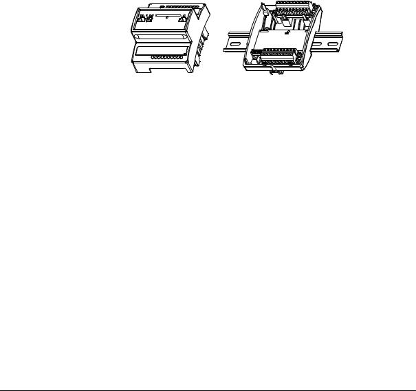
The Xenta device is designed around a microprocessor. The module consists of two parts, an electronics unit containing the circuit boards and contacts, and a terminal part including the terminal blocks.
Fig. 2.1: The Xenta device – Electronics and terminal.
•Power Outage Protection – Settings like configurations and web pages are stored in the non-volatile (flash) memory and will not be lost in the event of a power outage. A built-in capacitor maintains operation of the RAM memory for at least 72 hours in the event of a power outage.
•Real Time Clock – The real time clock provides the internal event log with a time stamp. The capacitor maintains operation of the clock for at least 72 hours in the event of a power outage.
•Mounting – The Xenta device is cabinet mounted on a TS 35 mm norm rail EN 50022.
To simplify commissioning, the terminal part can be pre-mounted in the cabinet.
If the Xenta device is to be wall-mounted, a wide range of standardized boxes are available.
Schneider Electric Buildings AB, Feb 2011 |
17 (134) |
04-00071-04-en |
|
2 TAC Xenta 500/700/911/913 |
TAC Xenta 500/700/911/913, Product Manual |
|
|
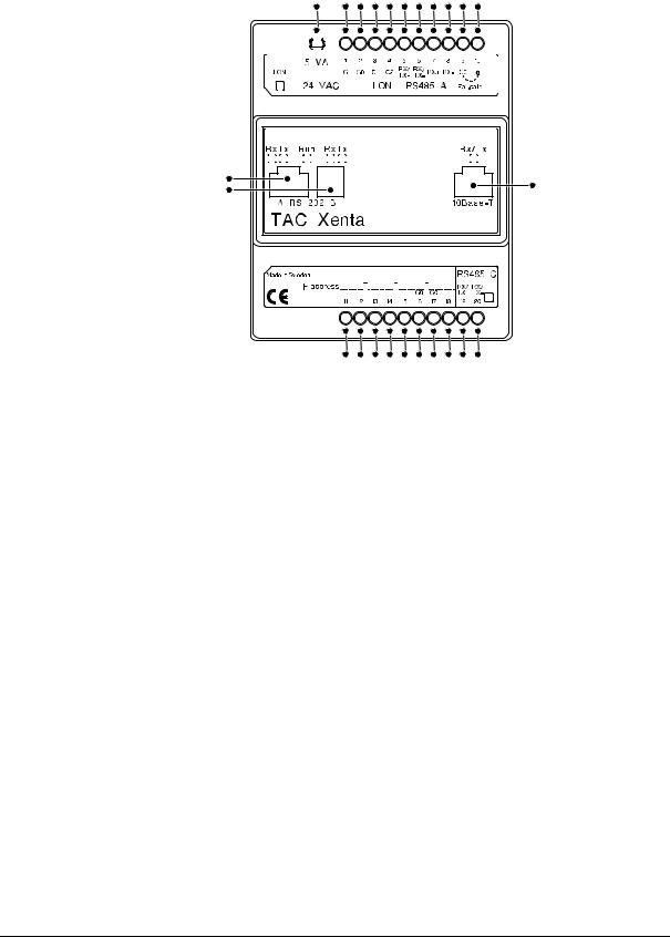
2.1.1Communication Interface
24 |
1 |
2 |
3 |
4 |
5 |
6 |
7 |
8 |
9 10 |
|||||||||||||||||||
|
|
|
|
|
|
|
|
|
|
|
|
|
|
|
|
|
|
|
|
|
|
|
|
|
|
|
|
|
|
|
|
|
|
|
|
|
|
|
|
|
|
|
|
|
|
|
|
|
|
|
|
|
|
|
|
|
|
|
|
|
|
|
|
|
|
|
|
|
|
|
|
|
|
|
|
|
|
|
|
|
|
|
|
|
|
|
|
|
|
|
|
|
|
|
|
|
|
|
|
|
|
|
|
|
|
|
|
|
|
|
|
|
|
|
|
|
|
|
|
|
|
|
|
|
|
|
|
|
|
|
|
|
|
|
|
|
|
|
|
|
|
|
|
|
|
|
|
|
|
|
|
|
|
|
|
|
|
|
|
|
|
|
|
|
|
|
|
|
|
|
|
|
|
|
|
|
|
|
|
|
|
|
|
|
|
|
|
|
|
|
|
|
|
|
|
|
|
|
|
|
|
|
|
|
|
|
|
|
|
|
|
|
|
|
|
|
|
|
|
|
|
|
|
|
|
|
|
|
|
|
|
|
|
|
|
|
|
|
|
|
|
|
|
|
|
|
|
|
|
|
|
|
|
|
|
|
|
|
|
|
|
|
|
|
|
|
|
|
|
|
|
|
|
|
|
|
|
|
|
|
|
|
|
|
|
|
|
|
|
|
|
|
|
|
|
|
|
|
|
|
|
|
|
|
|
|
|
|
|
|
|
|
|
|
|
|
|
|
21 |
23 |
|
22 |
||
|
11 12 13 14 15 16 17 18 19 20
Fig. 2.2: Connections on the Xenta device.
Table 2.1: Connections on the Xenta device.
Position |
|
|
Description |
|
|
||
|
|
||
1–2 |
Power supply. Minimum cross-sectional area 0.75 mm2 |
||
|
(AWG-19). |
||
|
• 1 (G) – 24 V AC (or DC+) |
||
|
• |
2 |
(G0) – Ground |
|
|
||
3–4 |
LonWorks TP/FT-10 connection. |
||
|
• |
3 |
(C1) |
|
• |
4 |
(C2) |
|
|
|
|
18 (134) |
Schneider Electric Buildings AB, Feb 2011 |
|
04-00071-04-en |

TAC Xenta 500/700/911/913, Product Manual |
|
2 TAC Xenta 500/700/911/913 |
|
|
|
|
|
|
Table 2.1: Connections on the Xenta device. (Contd.) |
||
|
|
|
|
|
Position |
|
Description |
|
|
|
|
|
|
|
|
|
5–8 |
RS-485 A connection. |
|
|
Internal |
• |
5 (RX/TX+) |
|
port A |
||
|
• |
6 (RX/TX-) |
|
|
|
||
|
|
• |
7 (RX+) |
|
|
• |
8 (RX-) |
|
|
Note that the interface RS-232 A (position 21) and |
|
|
|
interface RS-485 A (position 5–8) are internally con- |
|
|
|
nected to port A on the processor. Only one should be |
|
|
|
connected. |
|
|
|
|
|
|
9 |
Ground. |
|
|
|
• |
9 (G0) |
|
|
|
|
|
10 |
Fail-safe. |
|
|
|
|
|
|
11–15 |
Unused. |
|
|
|
|
|
|
16–17 |
Ground. |
|
|
|
• |
16 (G0) |
|
|
• |
17 (G0) |
|
|
|
|
|
18 |
Unused. |
|
|
|
|
|
|
19–20 |
RS-485 C (SDLC) connection. |
|
|
Internal |
• |
19 (RX/TX+) |
|
port C |
||
|
• |
20 (RX/TX-) |
|
|
|
||
|
|
|
|
|
21 |
RS-232 A connection. |
|
|
Internal |
Note that the interface RS-232 A (position 21) and |
|
|
port A |
||
|
interface RS-485 A (position 5–8) are internally con- |
||
|
|
||
|
|
nected to port A on the processor. Only one should be |
|
|
|
connected. |
|
|
|
|
|
|
22 |
RS-232 B console connection. |
|
|
Internal |
|
|
|
port B |
|
|
|
|
|
|
|
23 |
Ethernet 10Base-T connection. |
|
|
|
|
|
|
24 |
Service pin. |
|
|
|
|
|
Schneider Electric Buildings AB, Feb 2011 |
19 (134) |
04-00071-04-en |
|

2 TAC Xenta 500/700/911/913 |
TAC Xenta 500/700/911/913, Product Manual |
|
|
Caution
•G0 equals GROUND.
•Only G0 may be connected to protective ground.
20 (134) |
Schneider Electric Buildings AB, Feb 2011 |
|
04-00071-04-en |
TAC Xenta 500/700/911/913, Product Manual |
2 TAC Xenta 500/700/911/913 |
|
|
2.1.2Port Pins
Serial Port – RS-232 A
The RS-232 A port (position 21) is used for serial communication between the Xenta device and the connected unit. The connector is an 8-pin modular jack (RJ-45).
Note
•The interface RS-232 A (position 21) and interface RS-485 A (position 5–8) are internally connected to port A on the processor. Only one should be connected.
The port uses the following signals:
|
|
|
|
|
|
|
|
|
|
Table 2.2: Port pins – RS-232 A. |
|
|
|
|
|
|
|
|
|
|
|
|
|
|
|
|
|
|
|
|
|
|
|
1 |
CTS/RI (input) |
|
|
|
|
|
|
|
|
|
|
|
|
|
|
|
|
|
|
|
|
|
|
2 |
RTS (output) |
|
|
|
|
|
|
|
|
|
|
|
|
|
|
|
|
|
|
|
|
|
|
3 |
TxD (output) |
8 7 6 5 4 3 2 1 |
|||||||||||
|
|
|
|
|
|
|
|
|
|
|
|
|
|
|
|
|
|
|
|
|
|
4 |
RxD (input) |
|
|
|
|
|
|
|
|
|
|
|
|
|
|
|
|
|
|
|
|
|
|
5 |
Ground |
|
|
|
|
|
|
|
|
|
|
|
|
|
|
|
|
|
|
|
|
|
|
6 |
DSR (input) |
|
|
|
|
|
|
|
|
|
|
|
|
|
|
|
|
|
|
|
|
|
|
7 |
DCD (input) |
|
|
|
|
|
|
|
|
|
|
|
|
|
|
|
|
|
|
|
|
|
|
8 |
DTR (output) |
|
|
|
|
|
|
|
|
|
|
|
|
Fig. 2.3: Connection using hardware signals for modem communication.
Schneider Electric Buildings AB, Feb 2011 |
21 (134) |
04-00071-04-en |
|
2 TAC Xenta 500/700/911/913 |
TAC Xenta 500/700/911/913, Product Manual |
|
|
Serial Port – RS-232 B
The RS-232 B port is used for communication between the Xenta device and a computer. It is used for configuration of the Xenta device using Windows HyperTerminal. The connector is a 4-pin modular jack (RJ-10).
The port uses the following signals:
Table 2.3: Port pins – RS-232 B
|
|
|
|
|
|
|
|
1 |
TxD (output) |
|
|
|
|
|
|
|
|
|
|
|
|
|
|
|
|
|
|
2 |
RxD (input) |
|
|
|
|
|
|
|
|
|
|
|
|
|
|
|
|
|
|
3 |
Not used |
|
|
|
|
|
|
|
|||
4 3 2 1 |
|
||||||||
|
|
|
|
|
|
|
|
|
|
|
|
|
|
|
|
|
|
4 |
Ground |
|
|
|
|
|
|
|
|
|
|
Fig. 2.4: Connection using basic RS-232 signals, primarily intended for a computer running, for example Windows HyperTerminal during the configuration phase.
Ethernet Port – 10Base-T
The Ethernet 10Base-T port is used for communication between the
Xenta device and the TCP/IP network.
The port uses the following signals:
Table 2.4: Port pins – 10Base-T
|
|
|
|
|
|
|
|
|
|
1 |
TX+ |
|
|
|
|
|
|
|
|
|
|
|
|
|
|
|
|
|
|
|
|
|
|
2 |
TX- |
|
|
|
|
|
|
|
|
|
|
|
|
|
|
|
|
|
|
|
|
|
|
3 |
RX+ |
8 7 6 5 4 3 2 1 |
|
||||||||||
|
|
|
|
|
|
|
|
|
|
|
|
|
|
|
|
|
|
|
|
|
|
4–5 |
Connected to ground via 75 ohms |
|
|
|
|
|
|
|
|
|
|
|
|
|
|
|
|
|
|
|
|
|
|
6 |
RX- |
|
|
|
|
|
|
|
|
|
|
|
|
|
|
|
|
|
|
|
|
|
|
7–8 |
Connected to ground via 75 ohms |
|
|
|
|
|
|
|
|
|
|
|
|
Fig. 2.5: Connection for a LAN (Ethernet) cable.
22 (134) |
Schneider Electric Buildings AB, Feb 2011 |
|
04-00071-04-en |
TAC Xenta 500/700/911/913, Product Manual |
2 TAC Xenta 500/700/911/913 |
|
|
2.1.3Fail-Safe State
The Xenta can enter a fail-safe state if a severe problem arises in the system program.
The unit can be forced into fail-safe mode by shorting terminals 9 and 10 in Fig. 2.2 during power-up. This can be useful if the system program experiences problems.
The overall Run indicator (position 3 in Fig. 2.6) will show a steady red light in the fail-safe state.
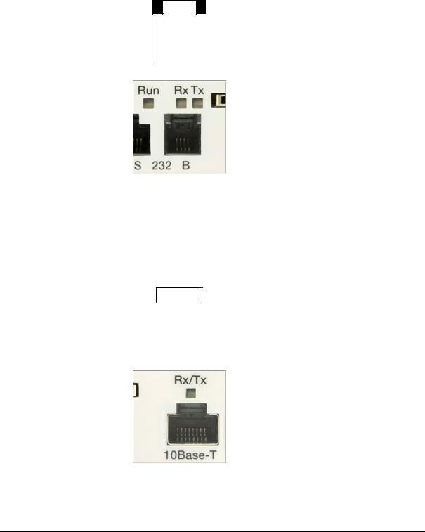
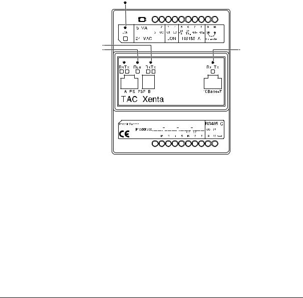
2.1.4LEDs
A number of light-emitting diodes (LEDs) on the Xenta device indicate that the application program is running and when communication is in progress.
1
2 
3 
 6
6
4 


 5
5
Fig. 2.6: LEDs on the Xenta device.
Table 2.5: LEDs on the Xenta device.
Position |
|
Description |
|
|
|
|
|
|
1 |
Neuron status indicator |
|
|
• Off – Normal mode |
|
|
• |
Red, blinking – Unconfigured mode |
|
• |
Red, steady – Hardware fault |
|
|
|
Schneider Electric Buildings AB, Feb 2011 |
23 (134) |
04-00071-04-en |
|
2 TAC Xenta 500/700/911/913 |
TAC Xenta 500/700/911/913, Product Manual |
|
|
|
|
|
Table 2.5: LEDs on the Xenta device. (Contd.) |
|
|
|
|
|
Position |
Description |
|
|
|
|
|
|
|
2 |
Serial RS-232 B port activity indicators: |
|
|
• RX – Indicates that data is received |
|
|
• TX – Indicates that data is transmitted |
|
|
|
|
3 |
Overall Run indicator |
|
|
• Green, steady – Normal mode |
|
|
• Green, blinking – Start mode |
|
|
• Red, steady – Fail-safe mode |
|
|
(see description below) |
|
|
• Red, blinking – Unit fault |
|
|
|
|
4 |
Serial RS-232 A port activity indicators: |
|
|
• RX – Indicates that data is received |
|
|
• TX – Indicates that data is transmitted |
|
|
|
|
5 |
Serial RS-485 C port activity indicator. |
|
|
|
|
6 |
Ethernet 10Base-T activity indicator |
|
|
|
Note
•The LEDs for the RS-232 A interface (position 4) do not indicate communication when using the RS-485 A interface although internal port A is used for both.
Serial Ports |
|
|
|
|
|
A |
|
|
|
RS-232 |
Port 21 |
|
|
|
|||
|
|
|
|
|
|
|
|
|
|
|
|
Processor |
|
|
RS-485 |
Port pins 5, 6 (7, 8) |
|
|
|
||||
|
|
|
|
||
B |
|
|
|
|
|
|
|
|
RS-232 |
Port 22 |
|
|
|
|
|||
C |
|
|
|
|
|
|
|
|
RS-485 |
Port pins 19, 20 |
|
|
|
|
|||
|
|
|
|
|
|
Fig. 2.7: Internal serial ports and RS-232/485 interfaces.
24 (134) |
Schneider Electric Buildings AB, Feb 2011 |
|
04-00071-04-en |

TAC Xenta 500/700/911/913, Product Manual |
2 TAC Xenta 500/700/911/913 |
|
|
2.2Configuring the TAC Xenta 500/700/911/913
The technician uses Microsoft Windows and HyperTerminal to initialize and configure the Xenta.
•For more information on how to connect the Xenta 511, see Section 4.1, “Configuration Phase”, on page 43.
•For more information on how to connect the Xenta 527, see Section 5.1, “Configuration Phase”, on page 53.
•For more information on how to connect the Xenta 555, see Section 6.1, “Configuration Phase”, on page 67.
•For more information on how to connect the Xenta 701/711/721, see Section 7.1, “Configuration Phase”, on page 79.
•For more information on how to connect the Xenta 731, see Section 8.1, “Configuration Phase”, on page 89.
•For more information on how to connect the Xenta 911, see Section 10.1, “Configuration Phase”, on page 105.
•For more information on how to connect the Xenta 913, see Section 11.1, “Configuration Phase”, on page 113.
2.2.1Configuration Data
To configure the Xenta, the following information should be obtained from the network administrator:
•DHCP is used or not used
•IP address (only if DHCP is not used)
•Subnet mask (only if DHCP is not used)
•Default gateway
•DNS server
•Web site name (can be set later, using XBuilder)
•Domain name (only used as information)
•Host name (only used as information)
This information is used once you have connected to the Xenta using
HyperTerminal and a serial cable (null modem cable).
Schneider Electric Buildings AB, Feb 2011 |
25 (134) |
04-00071-04-en |
|
2 TAC Xenta 500/700/911/913 |
TAC Xenta 500/700/911/913, Product Manual |
|
|
2.2.2Configuring Windows HyperTerminal
When you use Windows HyperTerminal you need to set up a connection. Once created it can be used when required. In the example below a Xenta 511 is configured.
To configure Windows HyperTerminal
1Connect the Xenta to the engineering PC.
2On the Start menu, point to All Programs, point to Accessories, point to Communications, and then click HyperTerminal.
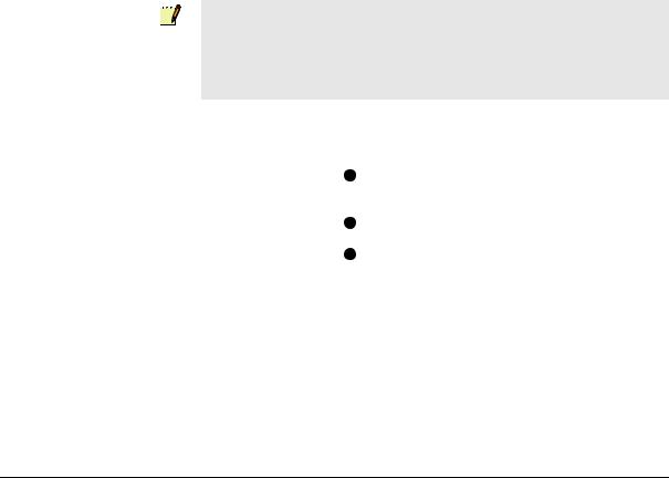
3In the Connection Description dialog box, in the Name box, type a name that describes the connection. In the example “Connection to Xenta 511”.
4In the Icon box, click the required icon.
5Click OK.
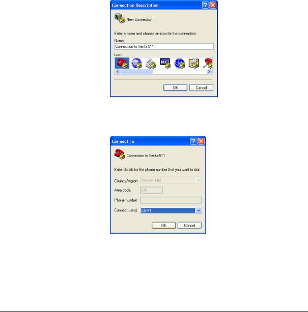
6In Connect To dialog box, in the Connect using list, click the COM port used in step 1 above.
7Click OK.
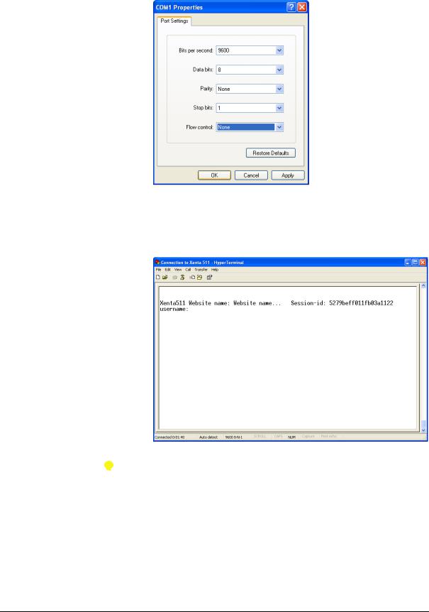
8In the COM1 Properties dialog box, in the Bits per second list, click 9600.
26 (134) |
Schneider Electric Buildings AB, Feb 2011 |
|
04-00071-04-en |
TAC Xenta 500/700/911/913, Product Manual |
2 TAC Xenta 500/700/911/913 |
|
|
9 In the Flow control list, click None.
10Click OK.
11On the File menu, click Save to save the HyperTerminal connection. The HyperTerminal for the Xenta is now ready to use.
12Press ENTER to activate the command prompt.
Tips
•To reopen the HyperTerminal connection to the Xenta, click
Start, point to All Programs, point to Accessories, point to Communications, point to HyperTerminal and then click Connection to Xenta 511.ht.
•You can also click Open on the File menu in HyperTerminal.
Schneider Electric Buildings AB, Feb 2011 |
27 (134) |
04-00071-04-en |
|

2 TAC Xenta 500/700/911/913 |
TAC Xenta 500/700/911/913, Product Manual |
|
|
2.2.3Configuring the TAC Xenta
The configuration parameters for the Xenta are entered using HyperTerminal. The parameters enable the Xenta to communicate using its TCP/IP port.
Important
•Because the Xenta’s TCP/IP default parameters are set at the factory, you can immediately access it using a web browser and change the parameters without having to use HyperTerminal. The default parameters are:
•IP address: 192.168.255.2
•Subnet mask: 255.255.255.0
To configure the TAC Xenta
1Start Windows HyperTerminal using the connection created in Section 2.2.2, “Configuring Windows HyperTerminal”, on page 26.
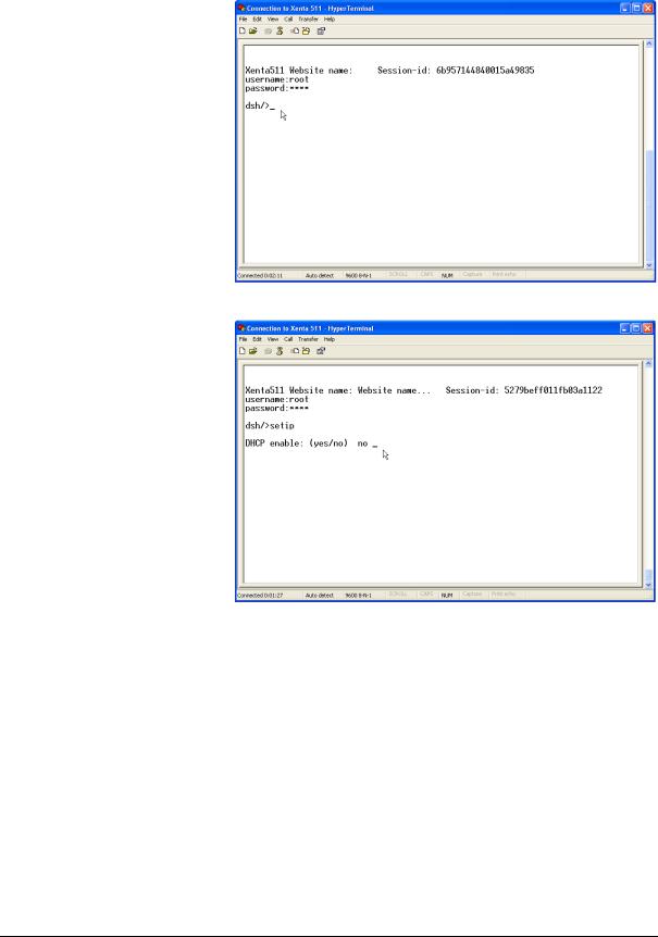
2Press ENTER to activate the command prompt.
3 Type the user name “root” and press ENTER.
28 (134) |
Schneider Electric Buildings AB, Feb 2011 |
|
04-00071-04-en |
TAC Xenta 500/700/911/913, Product Manual |
2 TAC Xenta 500/700/911/913 |
|
|
4 Type the password “root” and press ENTER.
5 Type the command “setip” and press ENTER.
6Type the configuration parameters, collected in Section 2.2.1, “Configuration Data”, on page 25. Press ENTER after each entry.
Schneider Electric Buildings AB, Feb 2011 |
29 (134) |
04-00071-04-en |
|

2 TAC Xenta 500/700/911/913 |
TAC Xenta 500/700/911/913, Product Manual |
|
|
In the example, the configuration parameters appear as follows.
The root password is not changed.
7Type the command “restart” and press ENTER, to activate the new configuration parameters.
8 Quit HyperTerminal.
The Xenta is now configured to communicate over TCP/IP, this means that you can access the Xenta through a web browser and that you can send web pages to the Xenta using XBuilder.
Important
•The password can be changed from a configuration page on the web site in the Xenta.
•The user name and the password are used by the operator when logging on to the web site and by XBuilder when sending the project to the Xenta.
30 (134) |
Schneider Electric Buildings AB, Feb 2011 |
|
04-00071-04-en |
 Loading...