


 Loading...
Instructions
1336 PLUS II Firmware Download Module
Catalog Number 1336F-FDM
What is Flash Memory?
This document provides information on upgrading the 1336 PLUS II firmware, including a description of the Flash memory used in the drive and the procedures required for downloading the latest firmware revision. For detailed drive information, refer to 1336 PLUS II User Manual, publication 1336 PLUS-5.3.
Important: To install updated firmware, the current drive firmware revision level must be 2.004 or higher. If your drive has a firmware version below 2.004, the Main Control Board must be replaced.
The drive firmware (including parameter layout and operating algorithms) resides in a form of programmable read-only memory called “Flash Memory.” Flash memory allows the user to easily upgrade the drive firmware locally using a standard computer and the supplied Firmware Download Module. The latest firmware files are available from your local Allen-Bradley Sales Office.
Firmware Download
Requirements
Required Communications
Cable
The necessary file can be downloaded to the module with a computer having the following:
•Disk drive (hard and/or floppy).
•Standard communications program capable of XMODEM protocol.
•Standard serial “COM” port and connecting cable (see below).
In addition, the following is recommended:
•IBM compatible computer with Microsoft Windows Operating System.
A standard serial communications cable wired as shown, is required. This cable interconnects the computer and Firmware Download Module.
Flash Download Module |
PC COM Port |
|
9 Pin Female |
9 Pin Male |
|
D-Shell Connector |
D-Shell Connector |
|
1 |
5 |
|
6 |
9 |
|
2 |
4 |
|
7 |
8 |
TX COM |
8 |
7 |
|
3 |
3 |
|
4 |
2 |
RX |
9 |
6 |
|
5 |
1 |
|

2 |
1336 PLUS II Firmware Download Module |
|
|
Main Control Board Power
Requirements
In order to upgrade firmware, the Main Control Board must have power applied. This can be accomplished through one of the following methods:
•Application of AC line voltage per instructions in Chapter 2 of the 1336 PLUS II User Manual. This is the normal method for installed drives.
•External power supply through the auxiliary 24V DC input at TB4 (B frame & up, see Auxiliary Inputs – TB4, TB6 in the User Manual).
•External power supply through power connector on module (all drives). This method does not power the entire logic section, but provides enough power to activate the flash memory. This is the best method for drives not yet installed. The external supply must provide 6.0 - 9.0V DC, 0.5A and is connected on the right-side of the module (see Figure 1).
Important: Do Not apply power until instructed to do so.
Installation Procedure |
Important: Updating the drive firmware will erase your current parameter |
|||
|
|
|
settings. Parameter settings should be saved before updating the |
|
|
|
|
firmware. |
|
|
Important: During the time that the flash memory is being upgraded, the |
|||
|
|
|
drive will be in a “non-operational state” and will not have the |
|
|
|
|
ability to control the motor. Be certain that placing the drive in |
|
|
|
|
a non-operational state is acceptable. |
|
|
|
|
|
|
|
! |
ATTENTION: This drive and module contain ESD |
||
|
(Electrostatic Discharge) sensitive parts and assemblies. |
|||
|
Static control precautions are required when installing, |
|||
|
|
|
||
|
|
|
||
|
|
|
testing, servicing or repairing this assembly. Component |
|
|
|
|
damage may result if ESD control procedures are not |
|
|
|
|
followed. If you are not familiar with static control |
|
|
|
|
procedures, reference publication 8000-4.5.2, “Guarding |
|
|
|
|
Against Electrostatic Damage” or any other applicable |
|
|
|
|
ESD protection handbook. |
|
|
! |
ATTENTION: To avoid a shock hazard, assure that all |
||
|
power to the drive has been removed before proceeding. In |
|||
|
addition, verify that the DC bus has discharged by |
|||
|
|
|
||
|
|
|
||
|
|
|
measuring across the “+DC” and “–DC” terminals of TB1 |
|
|
|
|
with a voltmeter. The voltage should be 0.0VDC. |
|
|
|
|
||
|
1. Remove and lock-out all incoming power to the drive. |
|||
|
2. If a HIM (or other snap-in module) is installed, remove it by carefully |
|||
|
|
squeezing the locking tabs-in and pulling-out. |
||
|
3. A Frame Drives - If a Control Interface Board (L option) is installed, |
|||
|
|
carefully remove the board by loosening the 2 captive screws. Position |
||
|
|
the board and attached wires off to the side of the chassis. |
||
|
4. Locate two spare jumpers on the Main Control Board and install them at |
|||
|
|
locations J14 and J20 (see Figure 1 on page 3 for locations). These |
||
|
|
jumpers allow the flash EEPROM to be overwritten with a new version |
||
|
|
of firmware. |
||
1336 PLUS II Firmware Download Module |
3 |
|
|
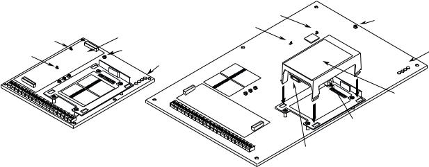
Figure 1 Component Locations
|
|
|
|
|
|
J14 |
|
|
|
|
|
|
|
|
|
|
|
Spare Jumpers |
|||||
|
|
|
|
|
|
J20 |
|
|
|
|
|
Control Interface Option Location |
|
|
|
|
|
||||||
J14 |
|
|
|
|
|
|
|
|
|
|
Status LEDs |
Spare Jumpers |
|
|
|
|
|||||||
J20 |
|
|
|
|
|
Status LEDs |
|
|
|
|
|
|
|
|
|
|
|
|
|
|
P |
||
|
|
|
|
|
|
|
|
|
SU |
OW |
|
|
|
|
|
|
|
|
|
|
R |
|
PP ER |
|
|
|
|
|
|
|
S |
|
|
LY |
|
|
|
|
|
|
|
F |
TO |
|
UN |
||
|
|
|
|
|
|
|
P |
|
|
||
|
|
|
|
|
|
AU |
LT |
|
|
|
|
|
|
|
|
P |
|
|
|
|
|
|
|
|
|
|
SU |
OW |
ER |
|
|
|
|
|
|
|
|
|
R |
|
PP |
|
|
|
|
|
|
|
S |
|
|
LY |
|
|
|
|
|
||
F |
TO |
|
UN |
|
|
|
|
|
|
||
|
P |
|
|
|
|
|
|
|
|
||
AU |
LT |
|
|
|
|
|
|
|
|
|
|
|
|
|
|
|
|
|
Flash |
||||
|
|
|
|
|
|
|
Download Module |
||||
|
|
|
|
|
|
External Power Connector |
|||||
Frames A1 - A4 |
Frames B - G |
|
Communications Connector |
File Identification
5.Install the Firmware Download Module in the Main Control Board cradle – place the guide tab into the slot, making sure the module connector lines up with the connector on the Main Control Board. Press the module until the 4 locking tabs lock in place.
6.Connect the communications cable (see page 1) between the 9 pin D-Shell Communications Connector on the Firmware Download Module and the selected computer COM port.
7.Apply power using one of the methods described on page 2. When power is applied, the POWER SUPPLY and STOP status LEDs on the Main Control Board should illuminate. If an external power supply is used, the FAULT LED may also be illuminated.
8.This procedure assumes that you are using Windows 95/98. The procedure may vary if a different computer/operating system is used.
A.To properly complete all download functions, two files (included on floppy disk) are required; a “readme” file and a “data” file. The files will have “.txt” and “.bin” file extensions, respectively (i.e.
V_x.xxxf.bin and Readxxxx.txt).
B.Using Windows Explorer, examine and verify the supplied file names using the information below.
V_ |
1 . |
004 |
|
f |
|
.bin |
||
|
|
|
|
Minor Revision |
|
Serial Flash |
|
|
Version |
|
Major Revision Level |
|
Level |
|
Version |
|
File Type |
|
|
Major rev levels may include |
|
Minor revs may |
|
The file for a 1336 |
|
bin=binary |
|
|
new features, updated drive |
|
include corrections |
|
PLUS II Drive must |
|
txt=text |
|
|
identification (newly released |
|
to languages, etc. |
|
have an “f.” |
|
|
|
|
sizes) or software corrections. |
|
|
|
|
|
|
Important:Verify that the “.bin” file has an “f” (V_x.xxxf.xxx). If you cannot locate the correct file, contact your local Sales Office.
C.Using Windows Explorer, copy the files to a convenient location on your computer.

41336 PLUS II Firmware Download Module
9.Locate the readme file on your computer using Windows Explorer. “Double-click” on the file to open/view it. The file information will be displayed on the screen, along with any notes concerning software changes or installation tips.
Establishing Communications with the Drive
Record the information below and close the window.
Item |
Readme File Information |
Current Drive Firmware |
(will be completed in Step 15) |
||
File Name |
|
|
|
|
|
Firmware Revision |
|
|
|
|
|
Boot Block |
|
|
|
|
|
DSP Main Block |
|
|
|
|
|
Setting Up the Communications Program
10.Start the XMODEM communications program. The following examples demonstrate the use of HyperTerminal (supplied with Windows 95 operating system). Other programs will be similar.
From the Start menu, choose:
“Programs -> Accessories -> HyperTerminal”
11.With the Hyperterminal window active, double click the Hypertrm.exe icon
Loading...