


R
Room Air Conditioner
Climatiseur de fenêtre
INSTALLATION AND OPERATING INSTRUCTIONS
MANUEL D'INSTALLATION ET D'UTILISATION
Models, Modèles: CW-XC64HU, CW-XC64HK, CW-C84GU |
CW-XC84GU, CW-XC84HU, CW-XC84HK |
Please read these operating instructions thoroughly
before using your air conditioner and keep for future reference.
Il est recommandé de lire attentivement ce manuel avant d'utiliser l'appareil. Conservez ce manuel.
For U.S customers :
For assistance, please call : 1-800-211-PANA(7262) or
Register your product at : http://www.panasonic.com/register
For customers in Canada :
For assistance, please call : 905-624-5505
CW382820391B
Au Canada : Pour de l'aide, composez le 905-624-5505.
Safety Precautions |
Before you call for service... Features and Installation About the Controls on the Air Conditioner
Safety Precautions
Safety Precautions ............. |
3 |
About the Controls on the Air Conditioner
Controls.............................. |
5 |
Remote Controller .............. |
7 |
Ventilation .......................... |
8 |
Air Direction........................ |
8 |
How to Secure Drain Pipe .... |
8 |
Care and Maintenance
Air Filter Cleaning............... |
9 |
Features |
|
Features ........................... |
10 |
Installation |
|
How to Install the Unit ...... |
11 |
Window Requirements ..... |
11 |
Installation Kit Contents ... |
12 |
Suggested Tool |
|
Requirements................... |
12 |
Cabinet Installation........... |
13 |
Electrical Data .................. |
15 |
Electrical Safety ............... |
16 |
Before you call for |
|
service... |
|
Normal Operation............. |
17 |
Abnormal Operation ......... |
17 |
FOR YOUR RECORDS
Staple your receipt to this page in case you need it later. Write down the model and serial numbers here:
Model #
Serial #
You can find them on a label on the side of each unit.
Dealer's Name
Date Purchased
READ THIS MANUAL
Inside you will find many helpful hints on how to use and maintain your air conditioner properly. Just a little preventive care on your part can save you a great deal of time and money over the life of your air conditioner.
You'll find many answers to common problems in the chart of troubleshooting tips. If you review our chart of Troubleshooting Tips first, you may not need to call for service at all.
CAUTION
•Contact the authorized Service technician for repair or maintenance of this unit.
•The air conditioner is not intended for use by young children or infirm persons without supervision.
•Young children should be supervised to ensure that they do not play with the air conditioner.
2
Safety Precautions
To prevent injury to the user or other people and property damage, the following instructions must be followed.
■Incorrect operation due to ignoring of instruction will cause harm or damage. The seriousness is classified by the following indications.
WARNING : This symbol indicates the possibility of death or serious injury.
CAUTION : This symbol indicates the possibility of injury or damage to property only.
■ Meanings of symbols used in this manual are as shown below.
Be sure not to do this.
Be sure to follow the instructions.
 WARNING
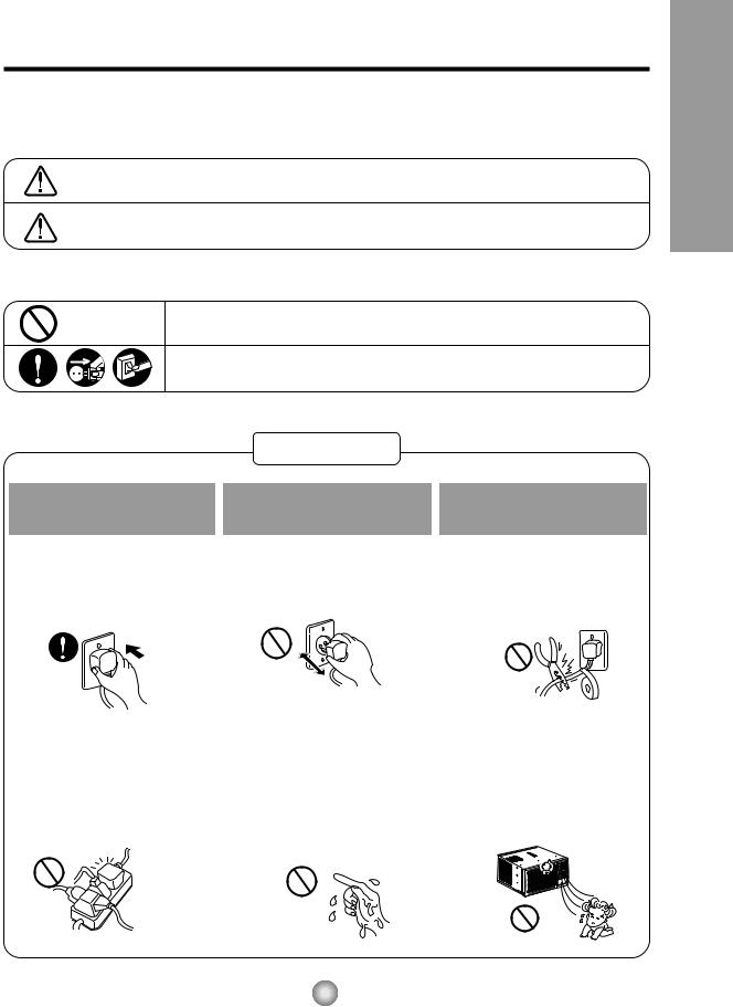
Plug in the power plug properly.
•Otherwise, it will cause electric shock or fire due to heat generation.
Do not operate or stop the unit by inserting or pulling out the power plug.
•It will cause electric shock or fire due to heat generation.
Do not damage or use an unspecified power cord.
•It will cause electric shock or fire.
•If the power cord is damaged, it must be replaced by the manufacturer or an authorized service center or a similarly qualified person in order to avoid a hazard.
Do not modify power cord |
Do not operate with wet |
Do not direct air flow at room |
length or share the outlet |
hands or in a damp |
occupants. |
with other appliances. |
environment. |
|
• It will cause electric shock or fire |
• It will cause electric shock. |
• This could lead to health |
|
due to heat generation. |
problems. |
|
Precautions Safety
3

Safety Precautions
When the air filter is to be removed, do not touch the metal parts of the unit.
• It may cause an injury.
|
|
|
Do not clean the air |
Ventilate well when used |
|
conditioner with water. |
together with a stove, etc. |
|
• Water may enter the unit and |
• An oxygen shortage may occur. |
|
degrade the insulation. It may |
|
|
cause an electric shock. |
|
|
When the unit is to be |
Do not put a pet or house |
Do not use for special |
|
cleaned, switch off, and turn |
plant where it will be exposed |
purposes. |
|
off the breaker. |
to direct air flow. |
|
|
|
|
|
|
• Since the fan rotates at high |
• This could injure the pets or |
• Do not use this air conditioner to |
|
speed during operation, it may |
plants. |
preserve precision devices, food, |
|
pets, plants, and art objects. |
|||
cause an injury. |
|
||
|
It may cause deterioration of |
quality, etc.
Do not operate switches |
Do not apply an insecticide |
Do not put a heater, etc. |
with wet hands. |
or flammable spray. |
where it is exposed to direct |
|
|
air flow. |
• It may cause an electric shock. |
• It may cause a fire or deformation |
• It may cause imperfect |
|
of the cabinet. |
combustion. |
4
About the Controls on the Air Conditioner
The controls will look like one of the following.
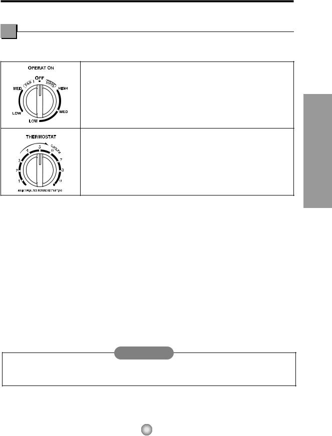
Controls
Model : CW-C84GU
|
Off |
- Turns air conditioner off. |
|
||
|
Med Fan |
- Med speed fan operation without cooling. |
|
Low Fan |
- Low speed fan operation without cooling. |
High Cool - Cooling with high speed fan operation.
Med Cool - Cooling with med speed fan operation.
Low Cool - Cooling with low speed fan operation.
This automatically controls the temperature of the indoor air.
Turn the knob so that arrow points to the higher number for greater cooling. Point the arrow to the lower number for more moderate cooling.
(i.e. the higher the number, the greater the cooling)
• FOR NORMAL COOLING
1. |
Turn the operation switch to the High Cool or the Low Cool setting. |
2. |
Set the Thermostat control to the desired temperature mark 5 (the mid-point is a good starting position). |
|
If the room temperature is not satisfactory after a reasonable time, adjust the control to a cooler or warmer |
|
setting, as appropriate. |
• FOR MAXIMUM COOLING
1.Turn the Operation Knob to the High Cool setting.
2.Set the Thermostat control to the largest (9) temperature mark.
• FOR QUIETER OPERATION
1.Turn the Operation Knob to the Low Cool setting.
2.Set the Thermostat control as needed.
CAUTION
When the air conditioner has performed its cooling operation and is turned off or set to the fan position, wait at least 3 minutes before resetting to the cooling operation again.
Conditioner Air the on Controls the About
5
About the Controls on the Air Conditioner
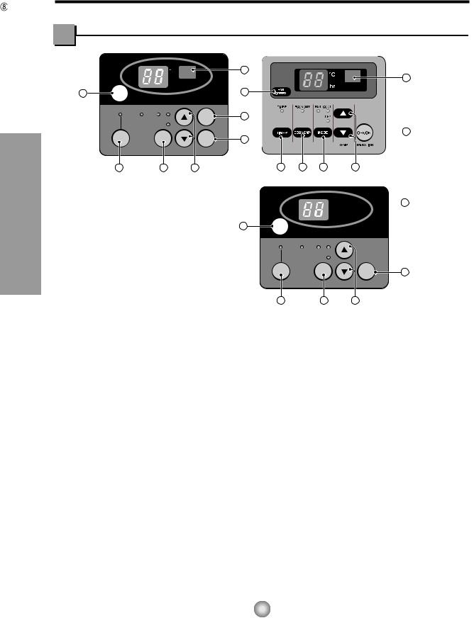
Controls
Model: CW-XC84HU |
Models: CW-XC64HK, CW-XC84HK |
F |
8 |
hr |
8 |
|
4 |
FAN |
4 |
SPEED |
ECONOMY FAN COOL
|
AIR |
7 |
DRY |
SWING |
|
|
|
 1
1
TIMER |
MODE |
OFF/ON |
1 |
|
TEMP |
OPERATION |
|
3 |
2 |
5 |
3 |
6 |
2 |
5 |
Models: CW-XC64HU, CW-XC84GU
OPERATION
•To turn the air conditioner ON, push the OFF/ON button.
To turn the air conditioner OFF, push the 4 button again.
•This button takes priority over any other buttons.
•When you first turn it on, the air conditioner is on the High cool mode and the temp. at 72°F (22°C)
 F
F  8 hr
8 hr
FAN |
SPEED |
ECONOMY |
FAN COOL |
|
|
|
DRY |
|
|
TIMER |
MODE |
OFF/ON |
1 |
|
TEMP |
OPERATION |
|
MODE |
|
|
3 |
|
2 |
5 |
|
|
|
|
Model: CW-XC80HU |
|
|
|
|||
• Evey time you push this button,it will toggle |
|
|
|
|
|
|||
|
|
TEMPERATURE SETTING |
|
|
||||
between COOL, FAN, DRY. |
|
|
• This button can automatically control the |
|
||||
(Models:CW-XC64HK,CW-XC84HK) |
|
|
temperature ofF the room. The temperature8 |
can |
||||
• Every time you push this button, it will |
|
4 |
be set within ahrrange of 60°F to 86°F by 1°F |
|||||
toggle between COOL,ECONOMY, FAN |
|
FAN |
|
|
|
|
|
|
|
|
|
(16˚C to 30˚C by 1˚C) Select the lower number |
|||||
and DRY. |
|
|
SPEED |
|
|
|
|
|
|
|
for lower temperature of the room. |
|
|||||
(Models:CW-XC64HU, CW-XC84HU, |
|
|
|
FAN COOL |
|
|
|
|
CW-XC84GU) |
|
|
ECONOMY |
DRY |
|
|
|
|
|
|
|
(Models:TIMER |
CWMODE-XC64HK, CW-XC84HK) |
|
|||
ON/OFF TIMER |
|
|
|
|
|
OFF/ON |
1 |
|
|
|
• If you push the button, the fan stops when the |
||||||
• Every time you push the TIMER button, |
|
|
|
|
TEMP |
OPERATION |
|
|
timer is set as follows. (1Hour → 2Hours → |
|
compressor stops cooling. |
|
|
||||
|
• Approximately every 3 minutes the fan will turn |
|||||||
3Hours → 4Hours → 5Hours → 6Hours → |
|
3 |
|
2 |
5 |
|
|
|
7Hours → 8Hours → 9Hours → 10Hours → |
|
on and check the room air to determine if |
|
|||||
|
cooling is needed. |
|
|
|
||||
11Hours → 12Hours → O) |
|
|
|
|
||||
|
|
|
|
|
|
|
||
• The Setting Temperature will be raised by |
|
AIR SWING |
|
|
|
|
||
2°F(1˚C) 30 min. later and by 2°F(1˚C) after |
|
• This button can automatically control the air flow |
||||||
another 30 min. |
|
direction. |
|
|
|
|
||
FAN SPEED |
|
REMOTE CONTROL SIGNAL RECEIVER |
|
|||||
• Every time you push this button it is set as follows. {High(F3) → Low(F1) → Med(F2) → High(F3)...}.
6

Remote controller
Precaution: The Remote Controller will not function properly if strong light strikes the sensor window of the air conditioner or if there are obstacles between the Remote Controller and the air conditioner.
Model: CW-XC84HU |
Models: CW-XC64HU, CW-XC64HK |
|
CW-XC84GU, CW-XC84HK |
1 |
OPERATION |
|
|
|
TEMP |
|
5 |
TIMER |
AIR |
SWING |
|
3 |
7 |
|
|
MODE |
FAN SPEED |
2 |
4 |
ECONOMY
6
OPERATION
•To turn the air conditioner ON, push the button. To turn the air conditioner OFF, push the button again.
•This button takes priority over any other buttons.
•When you first turn it on, the air conditioner is on the High cool mode and the temp. at 72°F (22˚C).
 MODE
MODE
•Every time you push this button, it will toggle between COOL, FAN and DRY. (Models:CW-XC64HK, CW-XC84HK)
•Every time you push this button,it will toggle between COOL, ECONOMY, FAN and DRY. (Models: CW-XC64HU, CW-XC84HU, CW-XC84GU)
 ON/OFF TIMER
- STOPPING OPERATION
•Every time you push this button, when the air conditioner is operating, timer is set as follows. (1Hour → 2Hours → 3Hours → 4Hours → 5Hours → 6Hours → 7Hours → 8Hours → 9Hours → 10Hours → 11Hours → 12Hours → O)
•The Setting Temperature will be raised by 2°F (1°C) 30 min. later and by 2°F (1°C) after another 30 min.
- STARTING OPERATION
•Every time you push this button, when the air conditioner is not operating, timer is set as follows. (1Hour → 2Hours → 3Hours → 4Hours → 5Hours → 6Hours → 7Hours → 8Hours → 9Hours → 10Hours → 11Hours → 12Hours → O)
1 |
OPERATION |
|
|
|
TEMP |
TIMER |
5 |
3 |
|
MODE |
FAN SPEED |
2
 4
4
ECONOMY
6
FAN SPEED
•Every time you push this button it is set as follows. {High(F3) → Low(F1) → Med(F2) → High(F3)...}.
 TEMPERATURE SETTING
•This button can automatically control the temperature of the room.
The temperature can be set within a range of 60°F to 86°F by 2°F.(16˚C to 30˚C by 1˚C) Select the lower number for lower temperature of the room.
 ECONOMY
•If the switch is set to "On", the fan stops when the compressor stops cooling. Approximately every 3 minutes the fan will turn on and check the room air to determine if cooling is needed.
AIR SWING
•This button can automatically control the air flow direction.
 DRY
DRY
•When this unit is in dry mode, the fan rotates in low speed. The fan stops when the compressor stops cooling.
Approximately every 3 minutes the fan will turn on and the unit checks the room air temperature to set itself.
Conditioner Air the on Controls the About
7
About the Controls on the Air Conditioner
Additional controls and important information.
Ventilation
The ventilation lever must be in the CLOSE position in order to maintain the best |
|
|
cooling conditions. When fresh air is necessary in the room, set the ventilation |
|
|
lever to the OPEN position. |
|
|
The damper is opened and room air is drawn out. |
CLOSE VENT OPEN |
|
|
||
NOTE: Before using the ventilation feature, and prior to installing the front grille, |
|
Part B |
|
|
|
pull down part until level with part . |
|
Part A |
Air Direction
The direction of air can be controlled wherever you want to cool by adjusting the horizontal louver and the vertical louver.
• VERTICAL AIR-DIRECTION CONTROL • HORIZONTAL AIR-DIRECTION CONTROL
Controlled |
Controlled |
Controlled by Remote |
manually |
manually |
Controller (Model: CW-XC84HU) |
The vertical air direction is adjusted by |
The horizontal air direction is adjusted by rotating |
rotating the horizontal louver forward or |
the vertical louver right or left manually or by |
backward manually. |
Remote Controller. |
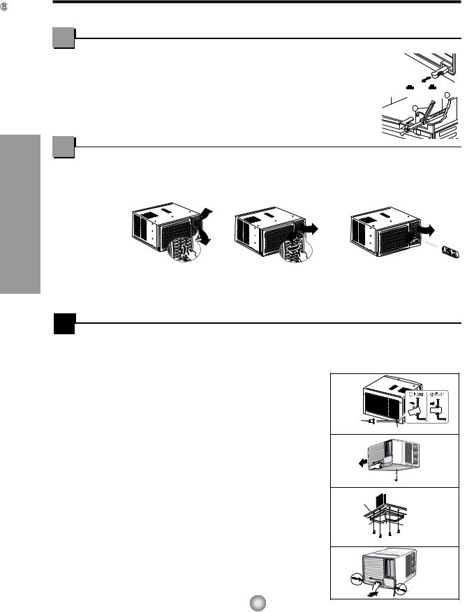
 How to Secure the Drain Pipe
In humid weather, excess water may cause the BASE PAN to overflow. To drain the water, remove the DRAIN CAP and secure the DRAIN PIPE to the rear hole of the BASE PAN. Press the drain pipe into the hole by pushing down and away from the fins to avoid injury.(See Fig.1)
Optional(CW3H02502C)
1.Remove the rubber plug and slide the chassis out from the cabinet.(See Fig.2)
2.Install the drain pan over the corner of the cabinet where you removed the plug with 4 (or 2) screws.(See Fig.3)
3.Connect the drain hose to the outlet located at the bottom of the drain pan. You can purchase the drain hose or tubing locally to satisfy your particular needs. (Drain hose is not supplied).(See Fig.3)
4.Select the most appropriate connection from among the figures to the right (by considering the hole of the unit) to fit drain pan to your own unit.(See Fig.3)
5.Slide the chassis back into the cabinet. Reinstall the cabinet screws. Secure the cabinet to chassis by using screws. (See Fig.4)
Drain pipe
Drain cap |
Fig. 1 |
Remove the |
rubber plug |
Fig. 2 |
CABINET |
|
DRAIN |
DRAIN HOSE |
Inside diameter 17mm (5/8") |
|
PAN |
|
 SCREW
SCREW
Fig. 3
Fig. 4
8
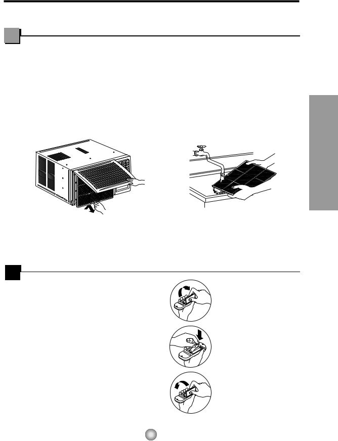
Care and Maintenance
TURN THE AIR CONDITIONER OFF AND REMOVE THE PLUG FROM THE POWER OUTLET.
Air Filter Cleaning
The air filter behind the front grille should be checked and cleaned at least once every 2 weeks or more often if necessary.
TO REMOVE:
1.Open the inlet grille upward by pulling out the bottom of the inlet grille or downward by pulling out the top of the inlet grille.
2.Using the tab, pull up slightly on the filter to release it and pull it down or up.
3.Clean the filter with warm, soapy water under 40°C (104°F).
4.Rinse and gently shake the water from the filter and let it dry before replacing it.
Conditioner Air the on Controls the About
CAUTION: DO NOT operate the air conditioner without a filter because dirt and lint will clog it and reduce performance.
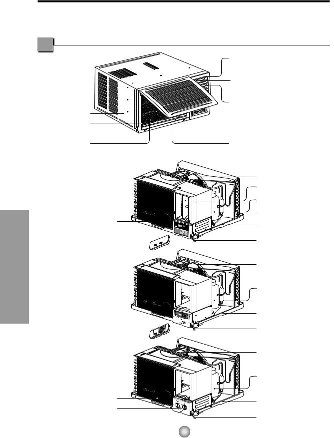
 How to Insert Batteries
1.Remove the cover from the back of the remote controller.
2.Insert two AAA dry cell batteries.
•Be sure that the (+) and (-) directions are correct.
•Be sure that both batteries are new.
3.Re-attach the cover.
•Do not use rechargeable batteries. Such batteries differ from standard dry cells in shape, dimensions, and performance.
•Remove the batteries from the remote controller if the air conditioner is not going to be used for an extended length of time.
9
Features
Learning parts name prior to installation will help you understand the installation procedure.
Features and Installation
CABINET |
FRONT GRILLE |
AIR FILTER
Models: CW-XC84HU
EVAPORATOR
F hr
CONTROL BOARD

REMOTE CONTROLLER 


Models: CW-XC64HK
CW-XC84HK
CW-XC64HU
CW-XC84GU
EVAPORATOR 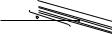
 CONTROL BOARD
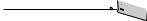


REMOTE CONTROLLER 

Model: CW-C84GU
EVAPORATOR
CONTROL BOARD
VERTICAL AIR DEFLECTOR (HORIZONTAL LOUVER)
HORIZONTAL AIR DEFLECTOR (VERTICAL LOUVER)
AIR DISCHARGE
AIR INTAKE (INLET GRILLE)
BRACE
VERTICAL LOUVER
COMPRESSOR
CONDENSER
BASE PAN
POWER CORD
BRACE
COMPRESSOR
 CONDENSER
BASE PAN
POWER CORD
BRACE
COMPRESSOR
 CONDENSER
BASE PAN
POWER CORD
10
INSTALLATION
How to Install the Unit
1.To prevent vibration and noise, make sure the unit is installed securely and firmly
2.Install the unit where the sunlight does not shine directly on the unit.
3.The outside of the cabinet must extend outward for at least 28cm (11") and there should be no obstacles, such as a fence or wall, within 50.8cm (20") from the back of the cabinet because it will prevent heat radiation of the condenser.
Restriction of outside air will greatly reduce the cooling efficiency of the air conditioner.
Cooled air
76.2cm (30")~ 152.4cm (60")
Fence
Awning
Heat radiation
About 12.7mm (1/2")
Over 50.8cm (20")
CAUTION: All side louvers of the cabinet must remain exposed to the outside of the structure.
4.Install the unit a little slanted so the back is slightly lower than the front (about 12.7mm (1/2")).
This will force condensed water to flow to the outside.
5.Install the unit with the bottom about 76.2cm (30")~152.4cm (60") above the floor level.
Window Requirements
NOTE: All supporting parts should be secured to firm wood, masonry, or metal.
This unit is designed for installation in standard double hung windows with actual opening widths from 55.88cm (22") to 91.44cm (36").
The top and bottom window sash must open sufficiently to allow a clear vertical opening of 38cm (15") from the bottom of the upper sash to the window stool.
|
|
|
|
|
|
|
|
|
|
|
|
|
|
|
|
|
|
|
|
|
|
|
55.8cm (22") to |
|
|
|
|
|
|
||||
|
|
|
|
|
|
|
|
|
|
|
|
|||||
|
|
|
|
|
|
91.44cm (36") |
|
|
|
|
|
|
||||
|
38cm (15") min |
Stool |
|
|
|
|
|
|
||||||||
(With frame curtain) |
|
|
|
|
|
Offset |
||||||||||
|
|
|
|
|
|
|
|
|
|
|
|
|
|
|
|
|
|
|
|
|
|
|
|
|
|
|
|
|
|
||||
|
|
|
|
|
|
|
|
|
|
|
|
|
|
|
|
12.7mm (1/2") to |
|
|
|
|
|
|
|
|
|
|
|
|
|
|
|
|
|
|
|
|
|
|
|
|
|
|
|
|
|
|
|
|
|
|
|
|
|
|
|
|
|
|
|
|
|
|
|
|
|
|
31.8mm (11/4") |
|
|
|
|
|
|
|
|
|
|
|
||||||
|
|
|
|
|
|
|
|
|
|
|
|
|
|
|
|
|
|
|
|
|
|
|
|
|
|
|
|
|
|
|
|
|
Sill |
|
|
|
|
|
|
|
|
|
|
|
|
|
|
|||
|
|
|
|
|
Interior wall |
|
|
|
Exterior |
|||||||
|
|
|
|
|
|
|
|
|
|
|
||||||
|
|
|
|
|
47cm (181/2") min. |
|
|
|
|
|
|
|||||
|
|
|
|
(Without frame curtain) |
|
|
|
|
|
|
|
|||||
|
|
|
|
|
|
|
||||||||||
Installation and Features
11
Features and Installation
Installation Kit Contents
1 |
2 |
3 |
4 |
|
|
5 |
6 |
7 |
8 |
11 |
9 |
10 |
|
|
|
|
|
12 |
|
|
|
|
|
Suggested Tool Requirements
NO. |
NAME OF PARTS |
Q'TY |
1 |
FRAME CURTAIN |
2 |
2 |
SILL SUPPORT |
2 |
3 |
BOLT |
2 |
4 |
NUT |
2 |
5 |
SCREW(TYPE A) (10mm (25/64")) |
16 |
6 |
SCREW(TYPE B)D5.1mm(3/16")/16mm(5/8") |
3 |
7 |
SCREW(TYPE C)D4.1mm(5/32")/16mm(5/8") |
5 |
8 |
FOAM-STRIP |
1 |
9 |
FOAM-PE (466mm x 10mm x 2mm) |
1 |
10 |
WINDOW LOCKING BRACKET |
1 |
11 |
FOAM-PE (920mm x 30mm x 2mm) |
1 |
12 |
DRAIN PIPE |
1 |
■Top retainer bar is in the product package.
SCREWDRIVER(+, -), RULER, KNIFE, HAMMER, PENCIL, LEVEL
PREPARATION OF CHASSIS
1.Remove the screws which fasten the cabinet at both sides and at the back.
2.Slide the unit from the cabinet by gripping the base pan handle and pulling while bracing the cabinet.
3.Cut the window sash seal to the proper length.
Peel off the backing and attach the FOAM-PE
 to the underside of the window sash.
4.Remove the backing from the top upper guide
FOAM-PE  and attach it to the bottom of the upper guide
5.Attach the upper guide onto the top of the cabinet with 3 type A screws from underneath the top of the cabinet.
6.Insert the Frame Curtain  into the upper guide.
11
(Type A)
5
7. Fasten the curtains to the unit with 4 Type
A screws.
5
12
Shipping
Screws
9
Lower guide
 5 (Type A)
Lower guide
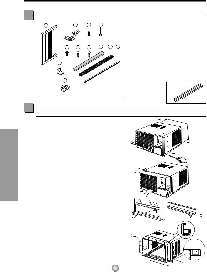
Cabinet Installation |
|
|
|
1. Open the window. Mark a line on |
|
|
|
center of the window sill (or desired |
|
|
|
air conditioner location). |
|
|
|
Carefully place the cabinet on the |
Upper Guide |
|
|
window sill and align the center mark |
|
|
|
|
Window sill |
||
on the bottom front with the center |
|
||
|
Front Angle |
Fig. 1 |
|
line marked in the window sill. |
|
|
|
(See Fig.1) |
Window Sash |
Upper guide |
|
|
|
||
2. Pull the bottom window sash down |
Foam-pe 11 |
|
|
behind the upper guide until it |
|
|
|
|
|
|
|
meets.(See Fig.2) |
Cabinet |
|
|
|
Frame Curtain 1 |
|
|
NOTE: |
Foam-pe 9 |
|
Fig. 2 |
|
|
|
|
• Do not pull the window sash down so |
|
|
|
|
|
tightly that the movement of Frame |
INDOOR |
OUTDOOR |
|
||
Curtain is restricted. |
|
||||
3. Loosely assemble the sill support |
|
Sill Support 2 |
|
|
|
using the parts in Fig. 3. |
Bolt 3 |
Nut 4 |
Fig. 3 |
|
|
|
|
||||
4. Select the position that will place the |
|
Screw (Type A) 5 |
|
|
|
sill support near the outer most point |
Frame Guide 9 |
|
/2") |
|
|
|
|
|
|||
on sill (See Fig. 4) |
|
|
|
1 |
andFeatures |
position using 2 Type A screws in |
|
|
|
About12.7mm ( |
|
5. Attach the sill support to the cabinet |
|
|
|
|
|
track hole in relation to the selected |
|
Cabinet |
|
|
|
|
|
|
|
|
|
each support (See Fig. 4). |
INDOOR |
OUTDOOR |
|
/(12.7mm12") |
Installation |
Adjust the bolt and the nut of sill |
|
||||
|
Fig. 4 |
|
|||
6. The cabinet should be installed with a |
Screw (Type B) 6 |
|
|
|
|
very slight tilt (about 12.7mm(1/2")) |
|
|
|
|
|
downward toward the outside (See |
|
|
|
|
|
Fig. 5). |
|
|
|
|
|
support for balancing the cabinet. |
|
|
|
About |
|
|
|
Sill support 2 |
|
||
|
|
|
|
||
7. |
Attach the cabinet to the window sill |
|
|
by driving the screws (Type B) |
Sash track |
|
through the front angle into window |
|
|
sill. |
|
8. |
Pull each Frame curtain fully to each |
|
|
window sash track, and repeat step 2. |
Front Angle |
|
|
|
|
|
Screw (Type B) 6 |
|
Sill support 2 |
Fig. 5 |
13
Features and Installation
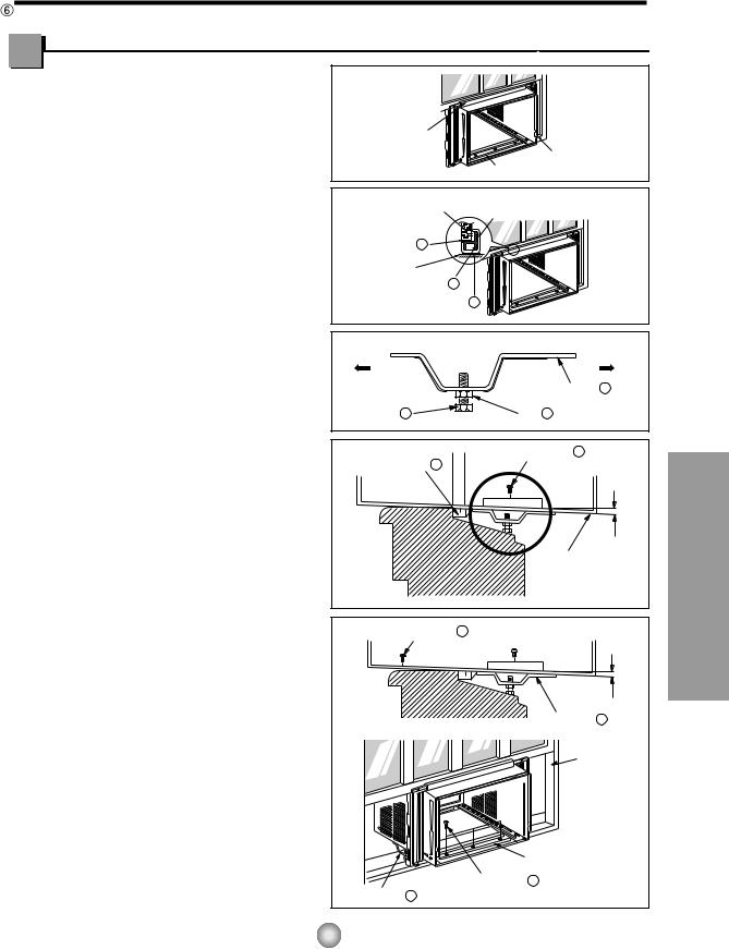
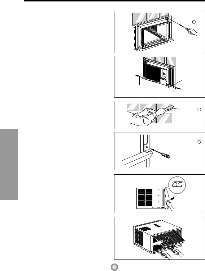
9.Attach each Frame curtain to the window sash using screws  (Type C). (See Fig. 6)
CAUTION: DO NOT DRILL A HOLE IN THE
BOTTOM PAN.
The unit is designed to operate with approximately 12.7mm (1/2") of water in bottom pan.
10. Slide the unit into the cabinet. (See Fig. 7)
CAUTION: For security purposes, reinstall screws at cabinet's sides.
11.Cut the foam-strip  to the proper length and insert between the upper window sash and the lower window sash.
(See Fig. 8)
Type C 7
Fig. 6
|
Power cord |
Screw |
|
Screw |
Fig. 7 |
|
Foam-Strip 8 |
Fig. 8 |
12.Attach the window locking bracket  with a type C screw. (See Fig. 9)
13.Attach the front grille to the cabinet by inserting the tabs on the grille into the tabs on the front of the cabinet. Push the grille in until it snaps into place. (See Fig.10)
NOTE: Please refer p.8 for setting ventilation kit.
14.Lift the inlet grille and secure it with two type two screws through the front grille. (See Fig. 11)
15.Window installation of room air conditioner is now completed. See ELECTRICAL DATA for attaching power cord to electrical outlet.
 Window locking bracket 10
Fig. 9
Fig. 10
Fig. 11
14
 Electrical Data
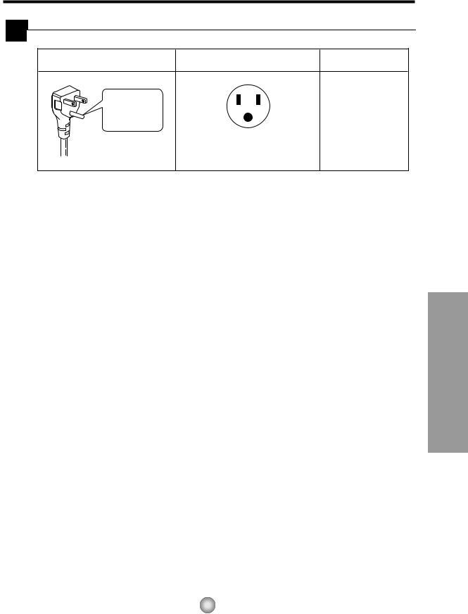
Line Cord Plug |
Use Wall Receptacle |
Power Supply |
Do not under any |
|
|
circumstances cut |
|
Use 15 AMP, time |
or remove the |
|
|
grounding prong |
|
delay fuse or circuit |
from the plug. |
|
breaker. |
|
|
|
Power supply cord with |
Standard 125V, 3-wire grounding |
|
3-prong grounding plug |
receptacle rated 15A, 125V AC |
|
USE OF EXTENSION CORDS
Because of potential safety hazards, we strongly discourage the use of an extension cord. However, if you wish to use an extension cord, use a CSA certified/UL-listed 3-wire (grounding) extension cord, rated 15A, 125V.
Installation and Features
15

 Electrical Data
Line Cord Plug |
Use Wall Receptacle |
Power Supply |
Do not under any |
|
|
circumstances cut |
|
Use 15 AMP, time |
or remove the |
|
|
grounding prong |
|
delay fuse or circuit |
from the plug. |
|
breaker. |
|
|
|
Power supply cord with |
Standard 125V, 3-wire grounding |
|
3-prong grounding plug |
receptacle rated 15A, 125V AC |
|
USE OF EXTENSION CORDS
Because of potential safety hazards, we strongly discourage the use of an extension cord. However, if you wish to use an extension cord, use a CSA certified/UL-listed 3-wire (grounding) extension cord, rated 15A, 125V.
Installation and Features
15
Features and Installation
Electrical Safety (Applies to USA and Puerto Rico)
IMPORTANT
(PLEASE READ CAREFULLY)
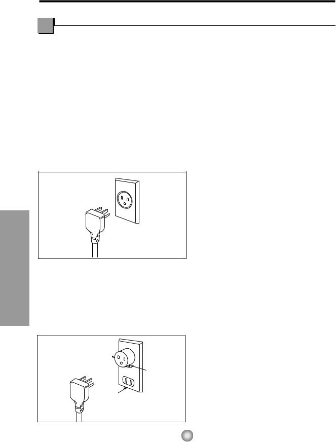
FOR THE USER'S PERSONAL SAFETY, THIS APPLIANCE MUST BE PROPERLY GROUNDED
The power cord of this appliance is equipped with a three-prong (grounding) plug. Use this with a standard three-slot (grounding) wall power outlet (Fig. 12) to minimize the hazard of electric shock. The customer should have the wall receptacle and circuit checked by a qualified electrician to make sure the receptacle is properly grounded.
PREFERRED METHOD
Ensure proper ground exists before use
Fig. 12
DO NOT CUT OR REMOVE THE THIRD (GROUND) PRONG FROM THE POWER PLUG.
A.SITUATIONS WHERE THE APPLIANCE WILL BE DISCONNECTED ONLY OCCASIONALLY:
TEMPORARY METHOD
Adapter plug 
Metal screw
Receptacle cover
Because of potential safety hazards, we strongly discourage the use of an adapter plug. However, if you wish to use an adapter, a TEMPORARY CONNECTION may be made. Use UL-listed adapter, available from most local hardware stores (Fig. 13). The large slot in the adapter must be aligned with the large slot in the receptacle to assure a proper polarity connection.
CAUTION: Attaching the adapter ground terminal to the wall receptacle cover screw does not ground the appliance unless the cover screw is metal, and not insulated, and the wall receptacle is grounded through the house wiring.
The customer should have the circuit checked by a qualified electrician to make sure the
receptacle is properly grounded.
Disconnect the power cord from the adapter, using one hand on each. Otherwise, the adapter ground terminal might break. DO NOT USE the appliance with a broken adapter plug.
B.SITUATIONS WHERE THE APPLIANCE WILL BE DISCONNECTED OFTEN.
Do not use an adapter plug in these situations. Unplugging the power cord frequently can lead to an eventual breakage of the ground terminal. The wall power outlet should be replaced by a three-slot (grounding) outlet instead.
USE OF EXTENSION CORDS
Because of potential safety hazards, we strongly discourage the use of an extension cord. However, if you wish to use an extension cord, use a CSA certified/UL-listed 3-wire (grounding) extension cord, rated 15A, 125V.
Fig. 13
16
Before you call for service...
Models: CW-XC64HU, CW-XC64HK, CW-XC84GU, CW-XC84HK, CW-XC84HU
Troubleshooting Tips save time and money!
Review the chart below first and you may not need to call for service.
Normal Operation
•You may hear a pinging noise caused by water being picked up and thrown against the condenser on rainy days or when the humidity is high. This design feature helps remove moisture and improve efficiency.
•You may hear the relay click when the compressor cycles on and off.
•Water will collect in the base pan during high humidity or on rainy days. The water may overflow and drip from the outdoor side of the unit.
•The fan may run even when the compressor does not.
 Abnormal Operation
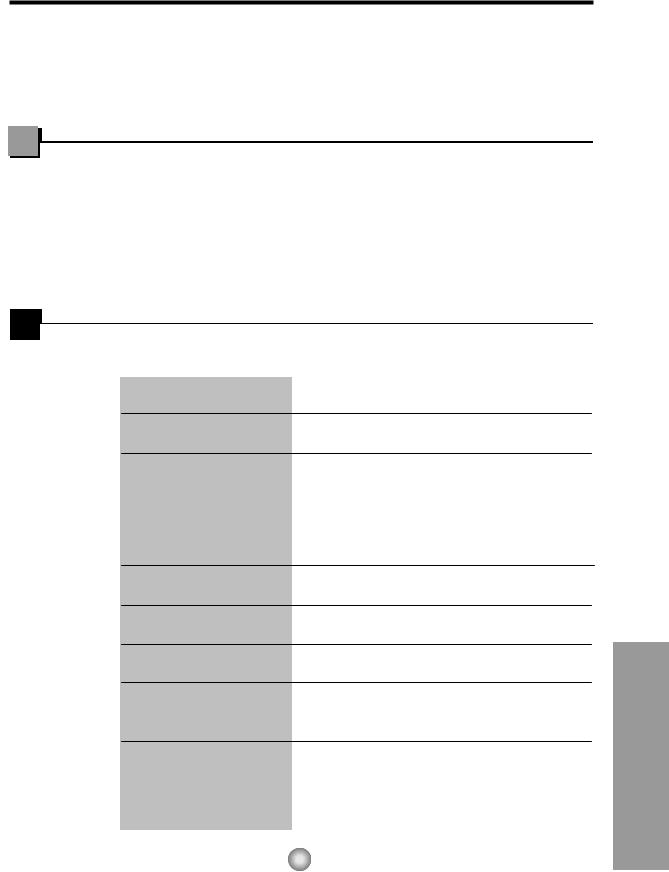
Problem |
Possible Causes |
What To Do |
|
|
|
|
|
|
■ The air conditioner is |
• Make sure the air conditioner plug is pushed |
|
|
unplugged. |
completely into the outlet. |
|
Air conditioner |
■ The fuse is blown/circuit |
• Check the house fuse/circuit breaker box and |
|
breaker is tripped. |
replace the fuse or reset the breaker. |
||
does not start |
|||
|
■ Power failure. |
• When power is restored, wait 3 minutes to restart the |
|
|
|
air conditioner to prevent tripping of the compressor |
|
|
|
overload. |
|
|
|
|
|
|
■ Airflow is restricted. |
• Make sure there are no curtains, blinds, or furniture |
|
|
|
blocking the front of the air conditioner. |
|
|
■ TEMP Control set to a |
• Set the TEMP Control to a lower number. |
|
|
higher number. |
|
Air conditioner does not cool as it should
■The air filter is dirty.
■The room may have been hot.
■Cold air is escaping.
•Clean the filter at least every 2 weeks. See the operating instructions section.
•When the air conditioner is first turned on
you need to allow time for the room to cool down.
•Check for open furnace floor registers and cold air returns.
•Set the air conditioner's vent to the closed position.
|
■ Cooling coils have iced up. |
• See Air Conditioner Freezing Up below. |
|
|
|
Air conditioner |
■ Ice blocks the air flow and |
• Set the mode control to High Fan at a high |
freezing up |
stops the air conditioner |
temperature. |
|
from cooling the room. |
|
|
|
|
...service for call you Before
17
Model: CW-C84GU
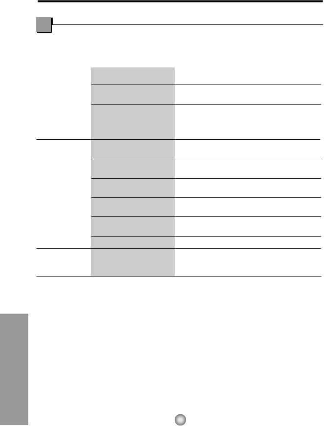
Problem |
Possible Causes |
What To Do |
|
|
|
|
|
|
■ The air conditioner is |
• Make sure the air conditioner plug is inserted |
|
|
unplugged. |
completely into the outlet. |
|
Air conditioner |
■ The fuse is blown/circuit |
• Check the house fuse/circuit breaker box and |
|
breaker is tripped. |
replace the fuse or reset the breaker. |
|
|
does not start |
|
||
|
■ Power failure. |
• If power failure occurs, turn the mode control to Off. |
|
|
|
When power is restored, wait 3 minutes to restart the |
|
|
|
air conditioner to prevent tripping of the compressor |
|
|
|
overload. |
|
Air conditioner does not cool as it should
■ Airflow is restricted. • Make sure there are no curtains, blinds, or furniture blocking the front of the air conditioner.
■The THERMOSTAT may • Turn the knob to a higher number. The highest not be set high enough. setting provides maximum cooling.
■The air filter is dirty. • Clean the filter at least every 2 weeks.
|
See the care and Maintenance section. |
■ The room may have been |
• When the air conditioner is first turned on, you need |
hot. |
to allow time for the room to cool down. |
■ Cold air is escaping. |
• Check for open furnace floor registers and cold air |
|
returns. |
■ Cooling coils have iced up. • See Air Conditioner Freezing Up below.
Air conditioner ■ Ice blocks the air flow and freezing up stops the air conditioner
from cooling the room.
•Set the mode control at Med Fan or High Cool with thermostat at 1 or 2.
Before you call for service...
18
 Loading...