


Operating Instructions
High-spec Wired Remote Controller
Model No. CZ-RTC5
Installation Instructions
Separately Attached.
ENGLISH
Before operating the unit, read these operating instructions thoroughly and keep them for future reference.
Panasonic Corporation
1006 Kadoma, Kadoma City, Osaka, Japan
Panasonic Corporation |
CV6233312187 |
http://www.panasonic.com |

Safety Precautions
WARNING
This symbol refers to a hazard or unsafe practice which can result in severe personal injury or death.
CAUTION
This symbol refers to a hazard or unsafe practice which can result in personal injury or product or property damage.
Matters to be observed |
|
Prohibited matters |
|
|
|
 WARNING
Do not use this appliance in a potentially explosive atmosphere.
In case of malfunction of this appliance, do not repair by yourself. Contact the sales or service dealer for repair.
In case of emergency, remove the power plug from the socket or switch off the circuit breaker or the means by which the system is isolated from the mains power.
 CAUTIONS
This appliance is intended to be used by expert or trained users in shops, in light industry and on farms, or for commercial use by lay persons.
This appliance can be used by children aged from 8 years and above and persons with reduced physical, sensory or mental capabilities or lack of experience and knowledge if they have been given supervision or instruction concerning use of the appliance in a safe way and understand the hazards involved.
•Do not operate with wet hands.
•Do not wash with water.
2 (EN)

Note:
This device complies with Part 15 of the FCC Rules. Operation is subject to the following two conditions: (1) This device may not cause harmful interference, and (2) this device must accept any interference received, including interference that may cause undesired operation.
This equipment has been tested and found to comply with the limits for a Class B digital device, pursuant to Part 15 of the FCC Rules. These limits are designed to provide reasonable protection against harmful interference in a residential installation. This equipment generates, uses and can radiate radio frequency energy and, if not installed and used in accordance with the instructions, may cause harmful interference to radio communications. However, there is no guarantee that interference will not occur in a particular installation. If this equipment does cause harmful interference to radio or television reception, which can be determined by turning the equipment off and on, the user is
encouraged to try to correct the interference by one or more of the following measures:
•Reorient or relocate the receiving antenna.
•Increase the separation between the equipment and receiver.
•Connect the equipment into an outlet on a circuit different from that to which the receiver is connected.
•Consult the dealer or an experienced radio/TV technician for help.
FCC Caution: To assure continued compliance, follow the attached installation instructions. Any changes or modifications not expressly approved by the party
responsible for compliance could void the user’s authority to operate this equipment.
(EN) 3

Thank you for purchasing the Panasonic high-spec wired remote controller.
Read the Operating Instructions carefully for safe use. This manual describes the Operating Instructions of the wired remote controller. Read this manual as well as operating instructions supplied with indoor units and outdoor units.
Be sure to read the “Safety Precautions” (P.2, 3) before using.
Keep this manual with operating instructions supplied with indoor units and outdoor units in a safe place.
Be sure to keep this manual in a place easily accessible by users. In the case of user change, be sure to give this manual to the new user.
NOTICE
The English text is the original instructions. Other languages are translation of the original instructions.
CONTENTS |
Page |
|
|
Safety Precautions............................... |
2 |
Preparations |
|
Part Names |
5 |
||
|
|||
• Control panel ....................................... |
5 |
|
|
• Screen display ..................................... |
6 |
|
|
|
|
|
|
..................................Basic Operations |
8 |
|
|
Menu List ............................................ |
10 |
|
|
Flap Setting for Each Indoor Unit .... |
12 |
How |
|
• FLAP |
12 |
||
|
|||
Flap Setting for Each Air Outlet ....... |
13 |
to |
|
• Lock indiv. flap |
13 |
||
Use |
|||
Timer Reservation |
14 |
||
|
|||
• ON/OFF timer .................................... |
14 |
|
|
• Weekly timer overview....................... |
15 |
|
|
• Weekly timer ...................................... |
16 |
|
|
|
|
|
|
................................Filter Information |
20 |
|
|
Quiet Operation/ |
|
|
|
Power Consumption Monitor............ |
22 |
|
|
Energy Saving .................................... |
24 |
|
|
• ECONAVI........................................... |
24 |
|
|
• Temp auto return................................ |
26 |
|
|
• Temp range........................................ |
27 |
Setting |
|
• Auto shutoff |
28 |
||
|
|||
• Schedule peak cut ............................. |
30 |
|
|
• Repeat off timer ................................. |
32 |
Change |
|
Outing Function ................................. |
33 |
||
Initial Settings .................................... |
35 |
||
• Clock/Clock type/Operation lock........ |
35 |
||
• Controller name ................................. |
36 |
|
|
• Touch sound/Contrast/Backlight/ |
|
|
|
Language .......................................... |
37 |
|
|
• Password change/Temp sensor/ |
|
|
|
Main/sub/Vent output/Contact address... |
38 |
|
|
Ventilation Setting.............................. |
40 |
|
|
Setting List.......................................... |
41 |
|
|
Troubleshooting |
43 |
When Necessary |
|
|
|||
Specifications..................................... |
45 |
|
|
|
|
|
4 (EN)

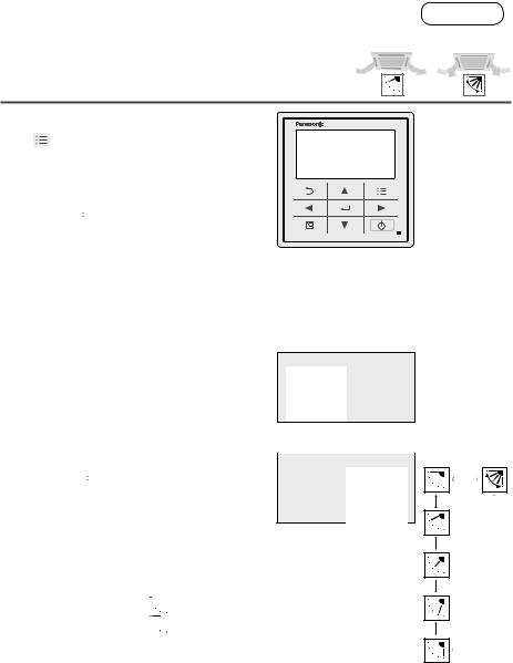
Part Names |
Control panel |
|
Return button |
|
Menu button |
Returns to the previous screen. |
Displays the menu |
|
|
|
screen (P. 10). |
LCD screen
Cross key buttons
Selects an item.
Up
Left |
Right |
|
Down |
|
|
|
|
|
Operation indicator |
|
|
|
|
|
|
|
|
|
|
|
|
|
|
|
|
|
Illuminates during operation. |
|
|
|
|
|
Blinks during alarm. |
|
|
|
Start/Stop button |
||
Energy saving |
|
||||
button |
Starts/Stops operation. |
||||
Switches Energy |
|
|
|
|
|
saving/Normal |
Enter button |
||||
operation. |
Fixes the selected content. |
||||
|
|
||||
Note
Press centre |
No glove |
No pen |
(EN) 5

Part Names Screen display
Top screen
|
|
|
|
|
Appears when |
|
|
|
|
|
|
|
|
Remote controller |
ECONAVI is |
Operation is |
|
Present time & |
|||||||||
being set to |
|
||||||||||||
name (P.36) |
|
ON. |
|
locked. (P.35) |
|
day (P.35) |
|||||||
|
|
|
|
|
|
|
|
|
|
|
Setting |
||
|
|
|
|
|
|
|
|
|
|
||||
|
|
|
|
|
|
|
|
|
|
|
|
||
|
|
|
|
|
|
|
|
|
|
|
|
information |
|
|
|
|
|
|
|
|
|
|
|
|
|
||
|
|
|
|
|
|
|
|
|
|
|
|
icon |
|
|
|
|
|
|
|
|
|
|
|
|
|
|
|
|
|
|
|
|
|
|
|
|
|
|
|
When |
|
|
|
|
|
|
|
|
|
|
|
|
|
||
|
|
|
|
|
|
|
|
|
|
|
|
checking the |
|
|
|
|
|
|
|
|
|
|
|
|
|
meanings |
|
Operation |
|
|
|
|
|
|
|
|
|
|
|
of all icons |
|
|
|
|
|
|
|
|
|
|
|
|
(P.41) |
||
mode |
|
|
|
|
|
|
|
|
|
|
|
|
|
|
|
|
|
|
|
|
|
|
|
|
|
|
|
Set temperature Fan speed Flap
The indoor unit is stopped or slight blow operation is in process.
When inspection is |
Appears if there is a |
|||
required (P.43) |
problem on ECONAVI. |
|||
|
|
|
|
|
|
|
|
|
|
|
|
|
|
|
|
|
|
|
|
Item selection |
Operation stop |
Lock screen display |
|||||
screen |
|
screen |
|
|
|
|
|
|
|
|
|
|
|
|
|
|
|
|
|
|
|
|
|
|
|
|
|
|
|
|
|
Cursor |
Operation guide (P.7) |
[Operation lock] is functioning. |
||
(P.35) |
|
|
||
|
|
|
|
|
|
|
To cancel lock |
||
|
|
Press |
|
button for |
|
|
4 seconds. |
||
6 (EN)

Setting information icons displayed on the top screen
Icon |
Description |
Page |
|
The indoor unit filter needs to be cleaned. |
P.20 |
|
|
|
|
The engine oil needs to be replaced. |
- |
|
(Only when using a gas heat pump air conditioner.) |
|
|
|
|
|
Switching operation modes is prohibited. |
- |
|
(Switching to Auto mode is also prohibited.) |
|
|
|
|
|
Remote control operation is restricted by a central control device. |
- |
|
|
|
|
[ON/OFF timer] is set. |
P.14 |
|
|
|
|
[Weekly timer] is set. |
P.15 |
|
|
|
|
Energy saving operation is in process. |
P.8 |
|
|
|
|
Fresh air is used for ventilation. |
|
|
(Only when connecting a heat exchange ventilation unit or |
P.40 |
|
connecting a commercially sold fan.) |
|
|
Prevents the room temperature from increasing too much (or |
P.33 |
|
decreasing too much) when no one is in the room. |
|
|
|
Menu screen (P.10)
Screen name Present time & day
Operation guide The currently operable content is simply displayed.
• ▲▼◄►: Cross key buttons
• 
 : Enter button
(EN) 7

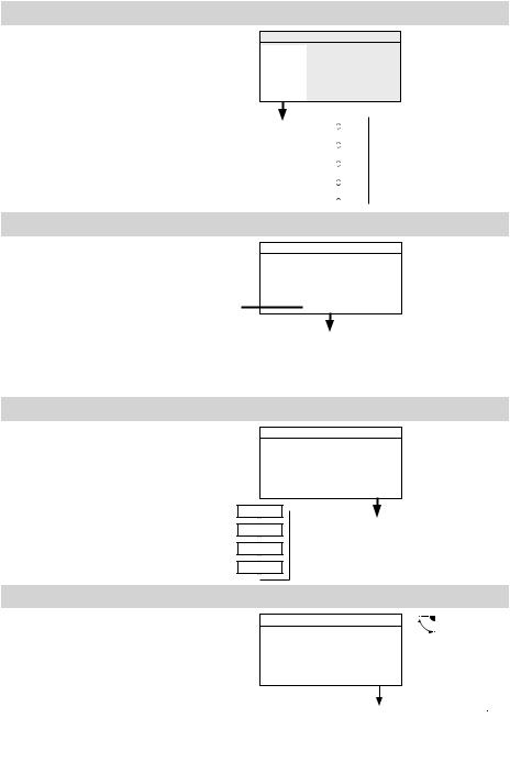
Basic Operations
1
2
3
Start operation.
Press  .
.
(The operation indicator illuminates.)
To change the setting
(P.10)
To turn the energy saving 


 operation ON/OFF
Press during operation.
(Only for models equipped with the energy saving function.)
To stop
(The operation indicator turns off.)
Select the item to set. |
Operation indicator |
||
|
|||
Press ◄ |
|
►. |
Energy saving operation |
|
|||
|
|||
Change the setting. |
is in process. |
||
|
|||
Press ▲▼ → |
|
. |
|
|
|
|
(The cursor disappears.) |
|
Note
Operation modes that cannot be set are not displayed.
The flap display differs from the actual flap angle.
Pressing  after recovery from mains power failure will resume operation with the contents before mains power failure has occurred.
If no operation is performed for a certain period of time, the backlight turns off to save electricity. (Press any button for illumination.)
The energy saving operation restricts the maximum current value, resulting in decreased cooling/heating performance.
(If the current of outdoor units does not reach the peak due to low load operation, the current value is not restricted.)
The temperature range that can be set varies depending on the model.
The set temperature range can be changed using the remote controller. (P.26)
Some models do not display the flap.
8 (EN)
Perform the following operations in step 2 on page 8.
Operation mode (e.g. Cool, Heat, etc.)
Press ◄.
|
|
Heat |
↓ |
*Auto: |
|
|
|
|
|
|
|
|
|
|
|
|
The mode is |
|
|
|
|
|
|
|
|
Dry |
|
||
|
|
|
automatically |
||
|
|
|
|
|
|
|
|
Cool |
|
switched to |
|
|
|
|
|
|
Cool or Heat to |
|
|
Fan |
|
||
|
|
|
achieve the set |
||
|
|
|
|
|
|
|
|
Auto |
|
temperature. |
|
|
|
|
|
|
|
Set temperature
Press 
 . (When the cursor is not visible)
Cursor
• Cool/Dry: 18 °C to 30 °C
• Heat : 16 °C to 30 °C
• Auto : 17 °C to 27 °C
Fan speed
Press ►.
High
Medium
Low
Auto
Flap
Press ► 2 times.
Flap Setting for Each Indoor Unit (P.12)
↓
*Auto: Cannot be selected in Fan mode.
•
 : Swing
•Pressing ▲▼ during swing can stop the flap at your preferred position.
•5-level adjustment
is possible 
 during Heat,

 Fan and Auto (Heat) modes.
(EN) 9

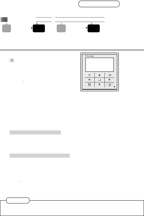
Menu List
1
2
Display the menu screen.
To return to the previous screen
Press  .
.
When no operation is performed in each setting screen for several minutes
The display returns to the top screen.
Select the menu item. |
Selectable menus (1 to 13) |
▲ ▼ → 

To turn the page
Press ◄ ►.
For details of screen examples, see the next page.
10 (EN)
Menu items (1 to 13)
1Basicinstructions
2FLAP*
3Lock indiv. flap*
4ON/OFFtimer
5Weekly timer
6Filter info*
7Outingfunction
8Quietoperation*
Power
9consumption monitor*
10Energysaving
11Initialsettings
Explains the basic |
|
|
operations. |
P.8 |
|
• Press ◄ ► to turn the |
||
|
||
page. |
|
Sets flaps for each indoor P.12 unit.
Fixes the flap of a specific |
P.13 |
|
|||
air outlet. |
|
|
|
||
|
|
|
|
|
|
Sets the ON/OFF timer |
P.14 |
|
|||
|
|
|
|
|
|
Sets the operation |
|
P.15 |
|
||
schedule on a daily basis. |
|
||||
|
|
|
|
|
|
Confirms and resets the |
P.20 |
|
|||
time to filter cleaning. |
|
||||
|
|
||||
|
|
|
|
|
|
Prevents the room |
|
|
|||
temperature from |
|
|
|
||
increasing to much (or |
P.33 |
|
|||
decreasing too much) |
|
|
|||
when no one is the room. |
|
|
|||
Performs quiet operation |
P.22 |
|
|||
for outdoor units. |
|
|
|||
|
|
|
|||
|
|
|
|
|
|
Confirms the power |
|
|
|||
consumptions on a daily, |
P.23 |
|
|||
weekly or yearly basis. |
|
|
|||
The energy saving |
|
|
|
||
functions shown on the |
|
|
|||
right can be set individually |
|
|
|||
|
|
||||
aside from the |
|
|
(Energy |
|
|
saving) button. |
|
|
|
|
|
12 |
Ventilation* |
Sets ventilation operation |
|
including the heat |
P.40 |
||
exchange ventilation unit. |
|
||
13 |
Setting list |
Confirms the meanings of |
P.41 |
setting information icons. |
|||
|
|
|
|
*Depending on the model, some menus cannot be used. The following display appears.
The administrator password is required for setting. (P.38)
No. 10 [Energy saving] details
|
The ECONAVI sensor |
|
|
ECONAVI |
detects human activity |
P.24 |
|
and conserves energy |
|||
|
|
||
|
based on the activity level. |
|
|
|
Restores the temperature |
|
|
Temp auto |
after the set time has |
P.26 |
|
return |
elapsed even if the |
||
|
|||
|
temperature is changed. |
|
|
Temp range |
Restricts the temperature |
P.27 |
|
range that can be set. |
|||
|
|
||
|
|
|
|
Auto shutoff |
Sets the auto shutoff |
P.28 |
|
timer. |
|||
|
|
|
|
Schedule |
Determines the time zone |
|
|
for the energy saving |
P.30 |
||
peak cut |
|||
operation. |
|
||
|
|
||
Repeat off |
Stops operation after a |
|
|
certain period of time |
P.32 |
||
timer |
each time operation is |
||
|
|||
|
performed. |
|
|
No. 11 [Initial settings] details |
|
||
|
|
|
|
Clock |
Sets the present date and |
|
|
time. |
|
||
|
|
||
|
|
|
|
Clock type |
Sets the type of clock |
P.35 |
|
display. |
|||
|
|
||
|
|
|
|
Operation |
Locks the button |
|
|
lock |
operations. |
|
|
Controller |
Names the remote |
P.36 |
|
name |
controller. |
||
|
|||
Touch |
Turns the operation sound |
|
|
sound |
ON/OFF. |
|
|
Contrast |
Sets the screen contrast. |
|
|
|
|
P.37 |
|
Backlight |
Sets the backlight |
||
|
|||
brightness of the screen. |
|
||
|
|
||
|
|
|
|
Language |
Sets the display language |
|
|
for the top screen. |
|
||
|
|
||
|
|
|
|
Password |
Sets the administrator |
P.38 |
|
change |
password. |
||
|
|||
|
Sets whether to use the |
|
|
Temp |
temperature sensor of the |
|
|
sensor |
remote controller or the |
|
|
|
indoor units. |
|
|
Main/sub |
Set this when 2 remote |
|
|
|
controllers are connected. |
P.39 |
|
Vent |
Interlocks the ON/OFF |
||
|
|||
of the air conditioner and |
|
||
output |
|
||
ON/OFF of the fan. |
|
||
|
|
||
Contact |
Confirms the contact |
|
|
address and telephone |
|
||
address |
|
||
number for servicing. |
|
||
|
|
||
(EN) 11
Flap Setting for Each Indoor Unit |
FLAP |
e.g. unit 1-1 |
e.g. unit 1-3 |
When setting flaps for each indoor unit |
|
• Flaps of all air outlets of 1 indoor unit face the same direction.
1
2
3
4
Display the menu screen.
To return to the previous screen
Press  .
.
To return to the top screen
Press  2 times.
Select [FLAP].
▲ ▼ → 

Select the indoor unit to set.
▲ ▼ → ►
•ALL: All units connected to the remote controller
e.g. (unit) ALL → 1-1 → 1-2 to 1-8
Select the flap direction. |
|
Swing |
|
▲ ▼ → 
(Press 2 times to finish.)
• Pressing ▲ or ▼ during swing can stop the flap at your preferred position.
• Pressing ▲ or ▼ while swing is stopped sets the flap at the specified position.
When ▲ is pressed 
 When ▼ is pressed

• 3-level adjustment is possible for Cool and Dry mode.
12 (EN)

Flap Setting for Each Air Outlet Lock indiv. flap
When setting the flap for each air outlet individually according to the room condition
•Even if the flap setting of all indoor units (P.9) or each indoor unit (P. 12) is changed, the flap directions set here are not changed.
1
2
3
4
5
Display the menu screen.
To return to the previous screen
Press  .
.
To return to the top screen
Press  2 times.
Select [Lock indiv. flap].
▲ ▼ → 

Select the indoor unit to set.
▲ ▼ → ►
e.g. 1-1 → 1-2 to 1-8
Select the air outlet.
▲ ▼ → ►
•The air outlet No. changes according to the installation direction. Check by actual operation.
Select the flap direction.
▲ ▼ → 
(Press 2 times to finish.)
•Although 


 is also displayed in Cool and Dry mode, the actual direction is


 .
.
*For types other than the 4-way cassette type, the following display appears and this function cannot be used.
1
2 
 4
4
 3
3
Swing


 Unlock

(EN) 13
Timer Reservation ON/OFF timer
This turns ON/OFF at the specified time. (e.g. Turning ON/OFF after 3 hours)
|
|
|
ON |
|
|
OFF |
|
|
OFF |
|
|
ON |
Set |
|
3 hours |
|
Operation |
Set |
|
3 hours |
|
Operation |
|||
|
|
|
|
|
stop |
|
|
|
|
stop |
||
•Use OFF timer for example when: Reducing electric consumption while sleeping
•Use ON timer for example when: Operating the air conditioner according to the meeting start timing
1
2
3
4
5
Display the menu screen.
To return to the previous screen
Press  .
.
To return to the top screen
Press  2 times.
Select [ON/OFF timer].
▲ ▼ → 

Select the timer type
▲ ▼ → 

• Select [OFF timer] or [ON timer].
Select [Set].
▲ ▼ → 

• To set the timer to OFF, select [Unset].
Set the time.
hour minute
▲ ▼ → ► → ▲ ▼ →

 →
→ 
(Press 2 times to finish.)
•Upper limit: Stops in 72 h. (by the 30 minutes)
Note
If ON timer and OFF timer are set to the same time, priority is given to OFF timer, and ON timer cannot be used.
14 (EN)
 Loading...