


Overhead 9q Widescreen Color LCD Monitor with Built-in DVD Player
CY-VHD9401N
Installation Instructions Einbauanleitung Instructions d’installation Installatiehandleiding Monteringsanvisningar Istruzioni per l’installazione Instrucciones de instalación Installationsanvisninger
≥Please read these instructions carefully before using this product and keep this manual for future reference.
≥Bitte lesen Sie diese Bedienungsanleitung vor der Verwendung dieses Produktes aufmerksam durch und bewahren Sie sie danach für spätere Nachschlagzwecke sorgfältig auf.
≥Prière de lire ces instructions attentivement avant d’utiliser le produit et garder ce manuel pour l’utilisation ultérieure.
≥Leest u deze instructie alstublieft zorgvuldig door voor u dit product in gebruik neemt en bewaar deze handleiding voor later gebruik.
≥Läs igenom denna bruksanvisning noga innan produkten tas i bruk. Spara bruksanvisningen för framtida behov.
≥Si prega di leggere attentamente queste istruzioni prima di usare questo prodotto e di conservare questo manuale per usi futuri.
≥Lea con atención estas instrucciones antes de utilizar el producto y guarde este manual para poderlo consultar en el futuro.
≥Læs venligst denne brugsvejledning grundigt, inden dette produkt tages i brug og gem den til senere konsultation.
NE |
Safety Information |
|
|
|
|
||||
G |
|
|
|
|
|
|
|
|
|
|
|
|
|
|
|
|
|
|
|
L |
|
|
|
|
|
|
|
|
|
I |
∫Read the operating instructions for the unit and |
∫This manual uses pictographs to show you how to |
|
|
|||||
S |
|
all other components of your car audio system |
use the product safely and to alert you to potential |
Warning |
qInstall the product after checking the position |
||||
H |
|
||||||||
|
|
carefully before using the system. They contain |
dangers resulting from improper connections |
Observe the following warnings when |
of the car’s pipes, tank and electrical wiring. |
||||
|
|
When opening holes in the car body to install |
|||||||
|
|
instructions about how to use the system in a |
and operations. The meaning of the pictographs |
||||||
|
|
installing. (Continued) |
the product, be careful not to touch or interfere |
||||||
|
|
safe and effective manner. Panasonic assumes |
are explained below. It is important that you fully |
||||||
|
|
qDo not install the product in a position where it |
with the pipes, tank or electrical wiring. Doing |
||||||
|
|
no responsibility for any problems resulting from |
understand the meanings of the pictographs in |
||||||
|
|
will interfere with the operation of the air bag. |
so could cause fire or accidents. |
||||||
|
|
failure to observe the instructions given in this |
order to use this manual and the system properly. |
||||||
|
|
The air bag may fail to operate properly or the |
qAlways use the accessories provided with the |
||||||
|
|
manual. |
|
|
|
|
|||
|
|
|
|
|
|
main unit or its parts could become dislodged |
product and the specified parts. |
||
|
|
|
|
|
|
|
|
||
|
|
|
|
|
|
|
|
||
|
|
|
|
This pictograph intends to alert |
|
This pictograph intends to alert |
|
and end up flying through the air by an air bag |
Using parts other than those specified could |
|
|
|
|
|
|
which has opened, causing an accident and/or |
damage the inside of the product or cause the |
||
|
|
|
|
you to the presence of important |
|
you to the presence of important |
|
||
|
|
|
|
|
|
injury. |
product to not be securely fastened and thus |
||
|
|
|
|
operating instructions and |
|
operating instructions and installation |
|
||
|
|
Warning |
|
installation instructions. Failure to |
|
Caution instructions. Failure to heed the |
|
qBe sure to use fuses with the prescribed |
come loose, which could cause accidents, |
|
|
|
|
heed the instructions may result in |
|
instructions may result in injury or |
|
capacity. Have a professional technician |
malfunction or fire. |
|
|
|
|
|
|
replace the fuses. |
qDo not install the product in a location where |
||
|
|
|
|
severe injury or death. |
|
material damage. |
|
||
|
|
|
|
|
|
Using fuses that exceed the prescribed capacity |
it will be subject to heavy vibration or in an |
||
|
|
|
|
|
|
|
|
||
|
|
|
|
|
|
|
|
||
|
|
|
|
|
|
|
|
could cause the product to start smoking, ignite |
unstable location. |
|
|
Warning |
qBe sure to disconnect the battery’s - terminal |
or otherwise malfunction. For replacement and |
Installing the product in a sloping location or on |
||||
|
|
while wiring and installing the product. |
repair of fuses, contact the store from which you |
a noticeably curved surface, etc. may cause the |
|||||
|
|
Observe the following warnings when |
|||||||
|
|
Doing the wiring and installation with the |
purchased your product or a nearby Panasonic |
product to shift out of position or drop down, |
|||||
|
|
installing. |
|
|
battery’s - terminal still connected could cause |
Service Centre. |
etc. while the car is moving, resulting in an |
||
|
|
qDo not, under any circumstances, install the |
electrical shock and injury due to a short circuit |
qContact your car dealer or manufacturer |
accident and/or injury. |
||||
|
|
product in a place where the driver’s ability to |
accidents. |
to determine the required procedure and |
qFollow the instructions to install and wire the |
||||
|
|
drive the car or the driver’s field of vision will |
qInstall the product securely so that it will not |
strictly follow their instructions before |
product. |
||||
|
|
be impaired. |
shift out of place or drop down. |
attempting installation of this product if your |
Failure to follow the instructions to properly |
||||
|
|
Installing the product in a place where it will |
Loose screws or insecure installation may cause |
car is equipped with air bag and/or anti-theft |
install and wire the product could cause |
||||
|
|
interfere with the driver’s field of vision either |
the product to shift out of position or drop |
systems. |
accidents or fire. |
||||
|
|
in front or behind or in a place where it will |
down, etc. while the car is moving, resulting in |
Specific procedures may be required for |
qRun the cords so that they do not interfere with |
||||
|
|
interfere with the driver’s ability to drive the car |
an accident and/or injury. |
connection and disconnection of the battery |
driving or with entering or exiting the car. |
||||
|
|
may lead to traffic accidents and/or injury. |
qDo not disassemble, repair or modify the |
to install this product. Failure to follow the |
Run the cords so that they do not wrap around |
||||
|
|
qHave a professional technician wire and install |
product. |
procedure may result in the unintended |
the steering wheel, gearshift, brake pedal, etc. |
||||
|
|
the product. |
Do not disassemble, repair or modify the |
deployment of air bags or activation of the |
or around your legs, and secure all the cords |
||||
|
|
Professional skill and experience is required |
product, or cut the cord to connect it to the |
anti-theft system resulting in damage to the car |
together. Failure to do so could cause accidents |
||||
|
|
to wire and install the product. Improper |
power supply for another device. This could |
and personal injury. |
or injury. |
||||
|
|
installation could result in failure of safety |
cause fire, electrical shock or other malfunction. |
|
|
||||
|
|
equipment resulting in accident and injury. |
qNever use the car’s safety equipment for |
|
|
||||
|
|
For safety’s sake, always ask the store from |
installing or grounding the product. |
NO WARRANTY |
|||||
|
|
which you purchased the product to install and |
Using the bolts, nuts and screws of the car’s |
Panasonic shall have no liability for reduction in safety or any accident caused by installing this |
|||||
|
|
wire it for you. |
safety equipment (steering and brake systems, |
||||||
|
|
product. We shall not guarantee any auto parts damaged during installation. |
|||||||
|
|
qUse in DC 12 V - grounded vehicles. |
fuel tank, etc.) could cause accidents. Follow |
||||||
|
|
|
|
||||||
|
|
This product is only for DC 12 V - grounded |
the instructions and only use the accessories |
|
|
||||
|
|
vehicles. It cannot be used in DC 24 V vehicles |
provided with the product and the specified |
|
|
||||
|
|
(such as large trucks, diesel vehicles designed |
parts. |
|
|
||||
|
|
for cold climates, etc.). |
|
|
|
|
|||
|
|
Using this product in such vehicles could cause |
|
|
|
|
|||
|
|
fire or other malfunction. |
|
|
|
|
|||
E N G L I S H
2 |
CY-VHD9401N |
|
CY-VHD9401N |
3 |
|
|
|
||
|
|
|
|
|

NE |
|
Safety Information (continued) |
|
||||
G |
|
|
|
|
|
|
|
|
|
|
|
|
|
|
|
L |
|
|
|
|
|
|
|
I |
|
|
|
|
|
|
|
S |
|
|
Caution |
qWear goggles or protective eyewear to shield |
≥The main unit weighs approximately 3 . Be |
||
H |
|
|
|||||
|
|
|
Observe the following cautions when |
your eyes from airborne metal particles during |
absolutely sure that the main unit is secured |
||
|
|
|
drilling. |
properly and does not come loose even with |
|||
|
|
|
installing. |
Failure to heed this caution may result in an |
vibration or shock. |
||
|
|
|
qDo not damage the cords. |
accident and/or injury. |
≥Check that there is sufficient strength in the |
||
|
|
|
Wire breaks and short circuits can cause |
qAs you cut the headliner, take care not to cut |
ceiling reinforcement crosspieces to hold the |
||
|
|
|
electrical shock or fire. |
your fingers. Also take care not to damage any |
weight of the product. |
||
|
|
|
Run the cords so that they do not get tangled in |
other areas of the headliner. |
≥Check the thickness of the interior materials, |
||
|
|
|
the moving parts (such as the seat rails), screws |
Failure to heed this caution may result in an |
attachment space, etc, refer to the attachment |
||
|
|
|
or car body. |
accident and/or injury. |
example (page 40) and determine the base plate |
||
|
|
|
Do not damage, pull too hard, fold, twist, or |
qWhen fitting the product, using the supplied |
attachment position. |
||
|
|
|
work on the cords. Do not place the cords near |
base plate, please ensure that it is properly |
≥Take care that the base plate or attachment |
||
|
|
|
heating appliances or put heavy objects on the |
secured to avoid excessive vibration or the |
screws do not pinch cords and wiring. Also take |
||
|
|
|
cords. |
chance of the product coming loose and |
care not to scratch or damage the ceiling or |
||
|
|
|
qInstall the monitor in a position where it will |
causing an accident. |
other parts of the vehicle. |
||
|
|
|
not hit anybody’s head when it opens and |
qThe metal plate, screws and nuts required to |
Observe the following cautions when |
||
|
|
|
attach the base plate are not supplied. |
||||
|
|
|
closes. |
using this unit or installing. |
|||
|
|
|
Failure to heed this caution may result in an |
The parts required for attaching the product |
|||
|
|
|
qIf an RCA or similar cord is to be connected |
||||
|
|
|
accident and/or injury. |
differ depending on the vehicle type. Consult a |
|||
|
|
|
qTake care not to injure your fingers with the |
professional technician for more details, and |
to the product, adjust its position and length |
||
|
|
|
power drill or other tool you are using. Also |
always have a professional technician wire |
so that it will not become entangled or come |
||
|
|
|
take care not to damage the wiring near the |
and install the product for you. |
into contact with your body. After use, be |
||
|
|
|
ceiling panel. |
qFollow local rules and regulations for |
absolutely sure to disconnect it from the |
||
|
|
|
Failure to heed this caution may result in an |
installing the unit. |
product. |
||
|
|
|
accident, injury and/or malfunctioning. |
Observe the following cautions for |
Failure to heed this caution may result in an |
||
|
|
|
accident and/or injury. |
||||
|
|
|
qDo not poke your fingers between the ceiling |
connections. |
qBefore connecting the product with another |
||
|
|
|
and this product. |
≥To prevent damage to the unit, be sure to follow |
device, consult the operating instructions |
||
|
|
|
Failure to heed this caution may result in an |
||||
|
|
|
the connection diagram. |
of the device concerned to ensure that the |
|||
|
|
|
injury and/or malfunctioning of the product. |
||||
|
|
|
≥Do not connect the power connector to the unit |
product and device will be connected properly. |
|||
|
|
|
qWear gloves for installation work to protect |
||||
|
|
|
until the wiring is completed. |
Incorrect connections may cause accidents |
|||
|
|
|
yourself from injuries. |
||||
|
|
|
≥When connecting stripped wires, be sure to |
and/or malfunctioning. |
|||
|
|
|
Failure to heed this caution may result in an |
||||
|
|
|
wrap them securely with electrical tape to |
Observe the following cautions when |
|||
|
|
|
accident and/or injury. |
||||
|
|
|
prevent shorts. |
||||
|
|
|
qTake care that the wiring is not pinched or |
replacing the bulb of the dome light. |
|||
|
|
|
≥Bundle all cables and keep cable terminals free |
||||
|
|
|
caught by the base plate attached to the roof |
from touching any metal parts. |
≥Have the dome light replaced by a qualified |
||
|
|
|
or any other parts. |
Observe the following cautions for |
specialist. |
||
|
|
|
Failure to heed this caution may result in an |
≥While you are replacing a bulb, be absolutely |
|||
|
|
|
accident and/or injury. |
installing the base plate |
sure to keep the dome light switch at OFF. |
||
|
|
|
qBefore installing the unit, be absolutely sure to |
≥Do not install the base plate as figure on page |
Otherwise, you may burn yourself. |
||
|
|
|
check that the screws do not make any contact |
38. |
≥The bulb is very hot to touch while it is lighted |
||
|
|
|
with the ceiling panel. |
One method for installing the main unit is to |
and immediately after it has gone off. |
||
|
|
|
If some space is required between the base plate |
use bond or adhesive tape (option) to fix wood |
≥Before attempting to replace it, turn the dome |
||
|
|
|
and the unit, attach and adjust the under cover. |
or plastic (option) to the ceiling panel before |
light switch off, wait several minutes and then |
||
|
|
|
For details on installing the under cover, consult |
attaching the base plate. However, the main unit |
check that it cooled off. |
||
|
|
|
your dealer. |
will not be securely installed using this method, |
≥Use a bulb with the specified ratings (12 V/5 W). |
||
|
|
|
|
|
|
and the bond may separate due to heat from |
Do not use any other bulb. |
|
|
|
|
|
|
the vehicle. Shock, impact, vibration or main |
≥Gripping the bulb with too much force may |
|
|
|
|
|
|
unit weight in this situation would be extremely |
break it. Wear fingerstalls or use some other |
|
|
|
|
|
|
dangerous. |
anti-slip method when replacing it. |
|
4 |
|
|
|
|
|
|
|
|
CY-VHD9401N |
|
|
|
||
|
|
|
|
|
|
|
|
|
|
|
|
|
|
|
|
Contents |
|
|
|
N |
|
|
|
|
E |
|
|
|
|
G |
|
|
|
|
|
|
|
|
|
L |
Safety Information |
Page 2 |
I |
||
S |
||||
Before Installation |
|
34 |
|
H |
|
|
|
||
Safety Installation Diagram ................ |
|
34 |
|
|
Open the Display Unit |
|
35 |
|
|
|
|
|||
Close the Display Unit ........................ |
|
35 |
|
|
Display Unit Lateral Angle |
|
|
|
|
Adjustment....................................... |
|
35 |
|
|
Installation Guide................. |
|
36 |
|
|
Supplied Hardware............................. |
|
36 |
|
|
Installation.......................... |
|
37 |
|
|
Introduction ....................................... |
|
37 |
|
|
Correct Example of Base Plate |
|
|
|
|
Installation ........................................ |
|
39 |
|
|
Attachment Example |
|
|
|
|
(without the Under Cover)................ |
|
40 |
|
|
Attachment Example |
|
|
|
|
(with the Under Cover)..................... |
|
40 |
|
|
Work Flow.......................................... |
|
41 |
|
|
Installation Procedures ...................... |
|
41 |
|
|
Electrical Connections ........... |
|
48 |
|
|
Wiring Diagram (Simple System)....... |
48 |
|
|
|
Wiring Diagram |
|
|
|
|
(Recommended System).................. |
|
50 |
|
|
Wiring Diagram |
|
|
|
|
(Advanced System) .......................... |
|
52 |
|
|
Note:
≥For replacing the bulb of the dome light, please refer to page 129 in the Operating Instructions.
CY-VHD9401N 5

E N G L I S H
1
Before Installation
Safety Installation Diagram |
Perform the adjustment below in order to provide the installation range shown in the figure on the left. |
≥This unit opens and closes at the maximum dimensions given below.
Approximately 150 mm* |
Installation angle: Less than 20˚ |


 Approximately 300 mm
Maximum |
Approximately |
120˚ |
300 mm |
*Install the product in such a way as to maintain the distances shown even when the display unit is rotated by 30˚ toward the front seat headrest (page 35).
 WARNING:
Have a professional technician wire and install the product.
Professional skill and experience is required to wire and install the product. Improper installation could result in failure of safety equipment resulting in accident and injury. For safety’s sake, always ask the store from which you purchased the product to install and wire it for you.
Open the Display Unit
[PUSH OPEN]
 Maximum
120x
1Push the display release button [PUSH OPEN] until the display is unlocked.
(Press the button with one hand while holding the display with the other.)
2Open the display unit by both hands until a comfortable viewing angle is reached.
Close the Display Unit
Move the display unit by both hands until the display release button is locked.
Note:
≥Always use both hands to open or close the display unit.
≥Always check that the display release button is locked after closing the display unit.
≥If the display unit cannot be locked, be sure to consult your dealer and remedy the situation.
Display Unit Lateral Angle
Adjustment
30x
30x
You can swivel it to the left and right, 30˚ each way.
Hold the display unit by the non-slip part in the upper half of it and adjust its lateral angle.
E N G L I S H
2
34 |
CY-VHD9401N |
|
CY-VHD9401N |
35 |
|
|
|
||
|
|
|
|
|
E N G L I S H
3
Installation Guide
 WARNING:
≥Use in DC 12 V - ground vehicles. This product is only for DC 12 V - grounded vehicles. It cannot be used in DC 24 V vehicles (such as large trucks, diesel vehicles designed for cold climates, etc.). Using this product in such vehicles could cause fire or other malfunction.
≥Be sure to disconnect the battery’s
- terminal while wiring and installing the product. Doing the wiring and installation with the battery’s - terminal still connected could cause electrical shock and injury due to a short circuit accidents.
≥Contact your car dealer or manufacturer to determine the required procedure and strictly follow their instructions before attempting installation of this product if your car is equipped with
air bag and/or anti-theft systems. Specific procedures may be required for
connection and disconnection of the battery to install this product. Failure to follow the procedure may result in the unintended deployment of air bags or activation of the anti-theft system resulting in damage to the car and personal injury.
Note:
≥Various settings that have been stored in the memory in other on-board equipment (car navigation etc.) may be lost if the battery terminals are disconnected.
Therefore, we recommend to make a record of or to back up the settings before disconnecting the terminals.
After completing installation of the main unit, set the equipment again according to the record.
For Installation
No. |
Item |
Diagram Q’ty |
1 |
Paper template |
1 |
|
Printed on the inside of |
|
|
the box. |
|
2 |
Under cover |
1 |
3 |
Base plate |
1 |
4 |
Screw |
6 |
|
(M5k25 mm) |
|
5 |
Spring washer |
6 |
|
(5 mm‡) |
|
6 |
Flat washer |
6 |
|
(5 mm‡) |
|
7 |
Screw (for resin) |
6 |
|
(2.6 mm‡k8 mm) |
|
8 |
Cord clamp |
2 |
9 |
Power connector |
1 |
Installation
 WARNING:
Have a professional technician wire and install the product.
Professional skill and experience is required to wire and install the product. Improper installation could result in failure of safety equipment resulting in accident and injury.
For safety’s sake, always ask the store from which you purchased the product to install and wire it for you.
 Caution:
≥Wear gloves for installation work to protect yourself from injuries. Failure to heed this caution may result in an accident and/or injury.
≥Wear goggles or protective eyewear to shield your eyes from airborne metal particles during drilling. Failure to heed this caution may result in an accident and/or injury.
≥When fitting the product, using the supplied base plate, please ensure that it is properly secured to avoid excessive vibration or the chance of the product coming loose and causing an accident.
≥The metal plate, screws and nuts required to attach the base plate are not supplied.
The parts required for attaching the product differ depending on the vehicle type. Consult a professional technician for more details, and always have a professional technician wire and install the product for you.
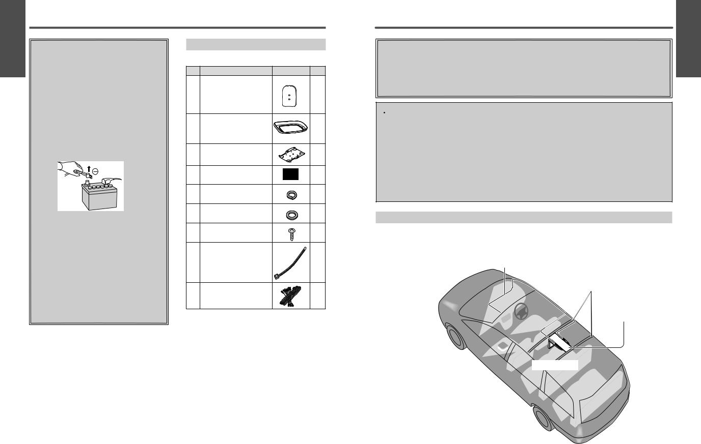
Introduction
A sample installation is shown below for your reference.
First remove the headliner. Next, firmly attach the metal plate (option) and the base plate to the two ceiling reinforcement crosspieces. Finally replace the headliner as it was and attach the main unit.
Wiring
Ceiling reinforcement crosspieces
Metal plate (option), base plate
CY-VHD9401N
E N G L I S H
4
36 |
CY-VHD9401N |
|
CY-VHD9401N |
37 |
|
|
|
||
|
|
|
|
|
 Loading...