


CU-TE9DKE
Order No. RAC0502005C2
Air Conditioner
CS-TE9DKE CU-TE9DKE
CS-TE12DKE CU-TE12DKE
CONTENTS
Page Page
1 Features 2
2 Functions
2.1. Remote Control
2.2. Indoor Unit
2.3. Outdoor unit
3 Product Specifications
4 Dimensions
4.1. Indoor Unit
4.2. Outdoor Unit
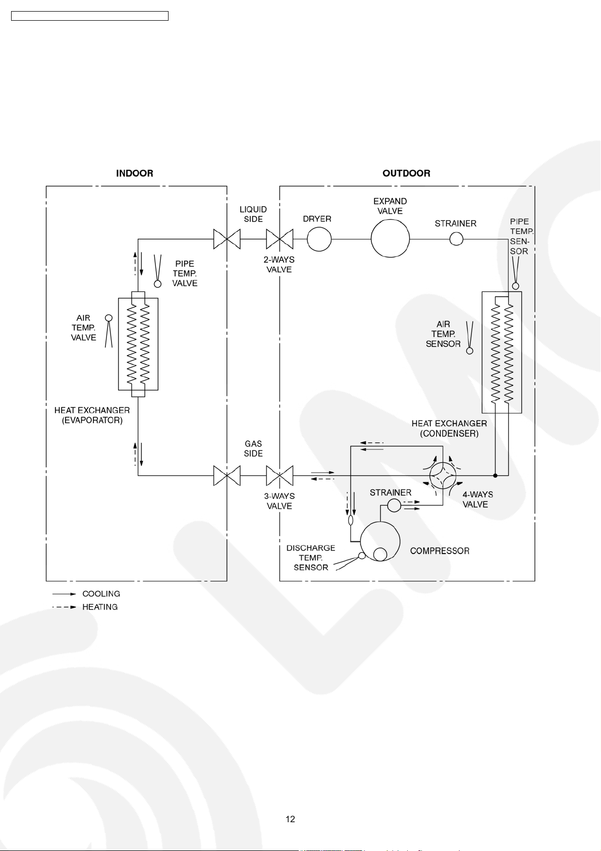
5 Refrigeration Cycle Diagram
6 Block Diagram
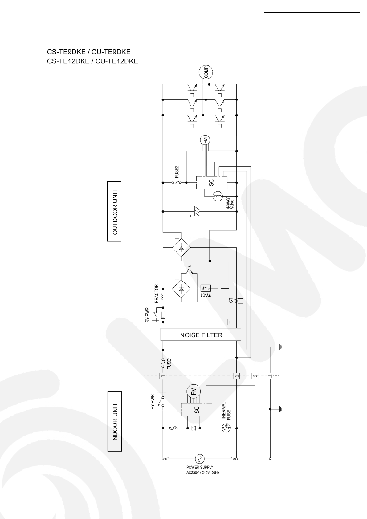
7 Wiring Diagram
7.1. CS-TE9DTE / CS-TE12DKE
10
10
11
12
13
14
14
3
3
4
5
6
7.2. CU-TE9DKE / CU-TE12DKE 15
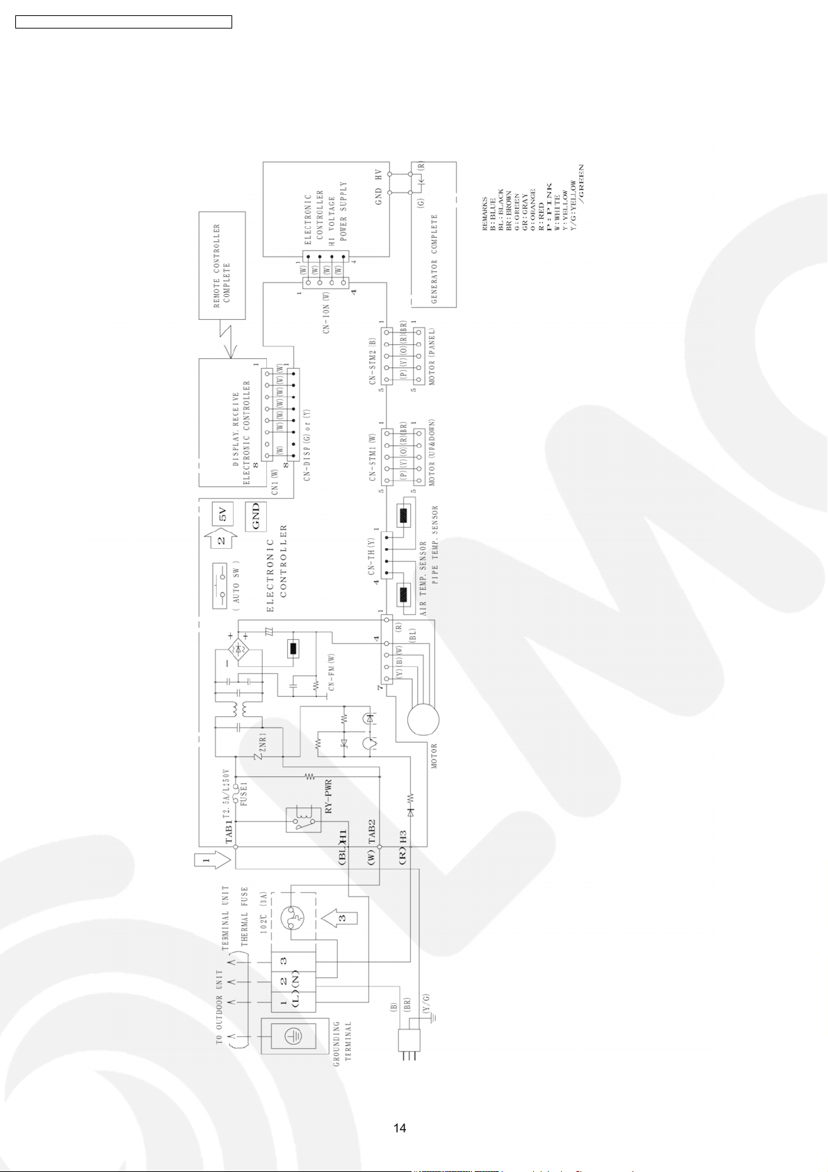
8 Electronic Circuit Diagram
8.1. Indoor Unit / Remote Controller
8.2. Outdoor Unit
9 Operation Details
9.1. BASIC FUNCTION
9.2. Indoor Power Relay Control
9.3. Room Air Temperature Control (Compressor Control)
9.4. Airflow Direction Control
9.5. Quiet operation (Cooling Mode / Cooling area of Dry
Mode)
9.6. Indoor Fan Control
9.7. Powerful Operation
© 2005 Matsushita Electric Industrial Co., Ltd. All
rights reserved. Unauthorized copying and
distribution is a violation of law.
16
16
18
20
20
21
21
23
24
26
29
CS-TE9DKE CU-TE9DKE / CS-TE 12DKE CU-TE12D KE
9.8. Automatic Operation 30
9.9. Timer Operation (24H Real Timer)
9.10. Auto Restart Control
9.11. Ionizer Operation
9.12. Protection Control
10 Operating Instructions
11 Installation Instructions
11.1. SAFETY PRECAUTIONS
11.2. INDOOR UNIT
11.3. OUTDOOR UNIT
12 Installation and Servicing Air Conditioner Using R410A
12.1. OUTLINE
12.2. TOOLS FOR INSTALLING /SERVICING REFRIGERANT
PIPING
12.3. REFRIGERANT PIPING WORK
1 Features
•
•
Product
• •
−
−
Microcomputer-controlled compressor operating
− −
frequency.
−
−
Vertical airflow direction.
− −
−
−
Four modes of operation selection.
− −
−
−
Air filter with function to reduce dust and smoke.
− −
−
−
SUPER Alleru-buster filter inactive various harmful
− −
airborne elements including allergens, viruses and
bacteria.
−
−
Ionizer control for generate negative ion in discharge air.
− −
−
−
Quiet mode to provide quiet operation.
− −
−
−
24-hour timer setting.
− −
−
−
Long installation piping up to 15 meters.
− −
•
•
Quality Improvement
• •
−
−
Random auto restart after power failure for safety restart
− −
operation.
−
−
Gas leakage detection.
− −
12.4. INSTALLATION, TRANSFERRING, SERVICING 57
13 Servicing Information
31
31
32
33
34
40
40
43
46
49
49
50
54
13.1. About Lead Solder (PbF)
13.2. TROUBLESHOOTING
13.3. BREAKDOWN SELF DIAGNOSIS FUNCTION
13.4. DISASSEMBLY OF PARTS
14 Technical Data
14.1. Operation Characteristics
14.2. Sensible Capacity Chart
15 Exploded View and Replacement Parts List
15.1. Exploded View (Indoor Unit)
15.2. Replacement Parts List (Indoor Unit)
15.3. Exploded View (Outdoor Unit)
15.4. Replacement Parts List (Outdoor Unit)
61
61
62
64
66
74
74
76
77
77
78
79
80
•
•
Serviceability
• •
−
−
Removable and washable front panel.
− −
−
−
Breakdown self diagnosis function .
− −
•
•
Environmental Protection
• •
−
−
Non-ozone depletion substances refrigerant (R410A).
− −
2
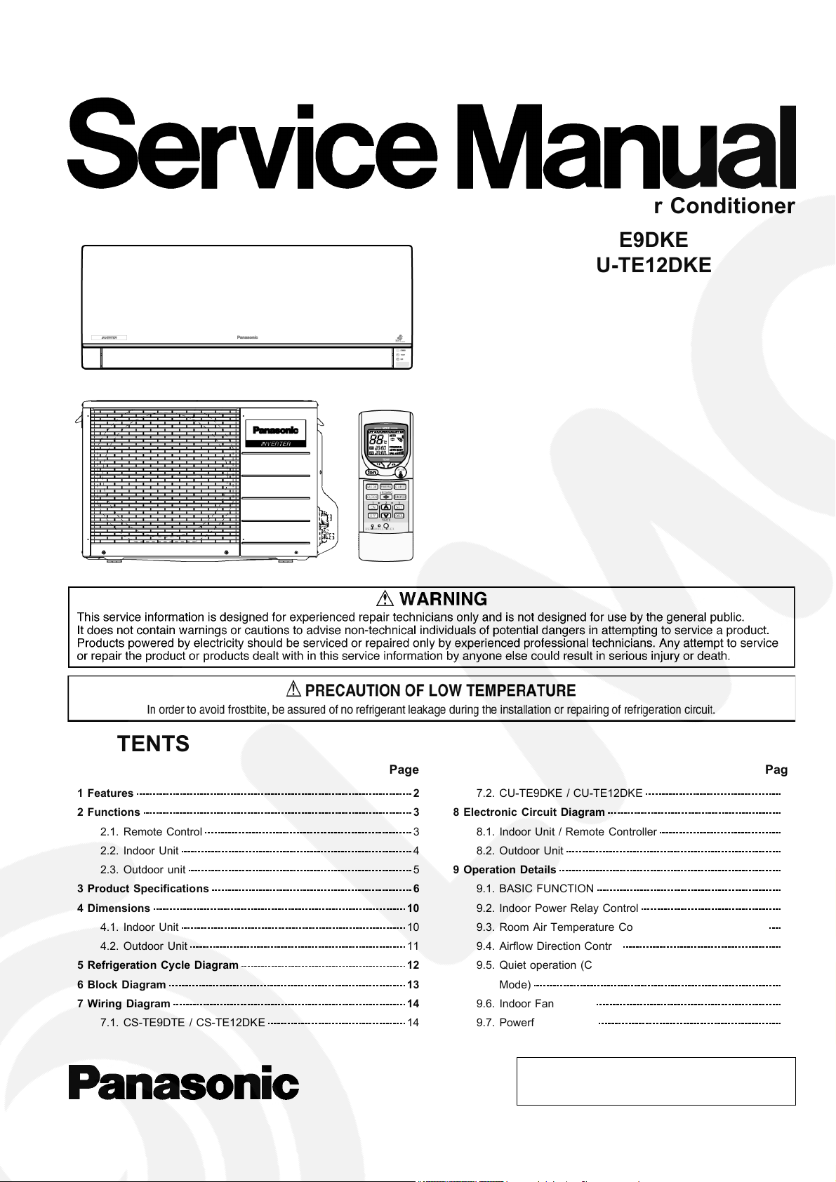
2 Functions
2.1. Remote Control
CS-TE9DKE CU-TE9DKE / CS-TE 12DKE CU-TE12D KE
3

CS-TE9DKE CU-TE9DKE / CS-TE 12DKE CU-TE12D KE
2.2. Indoor Unit
4
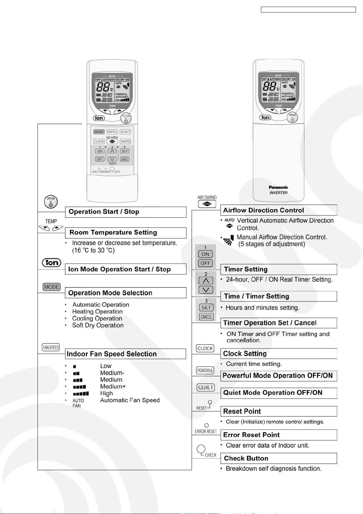
2.3. Outdoor unit
CS-TE9DKE CU-TE9DKE / CS-TE 12DKE CU-TE12D KE
5
CS-TE9DKE CU-TE9DKE / CS-TE 12DKE CU-TE12D KE
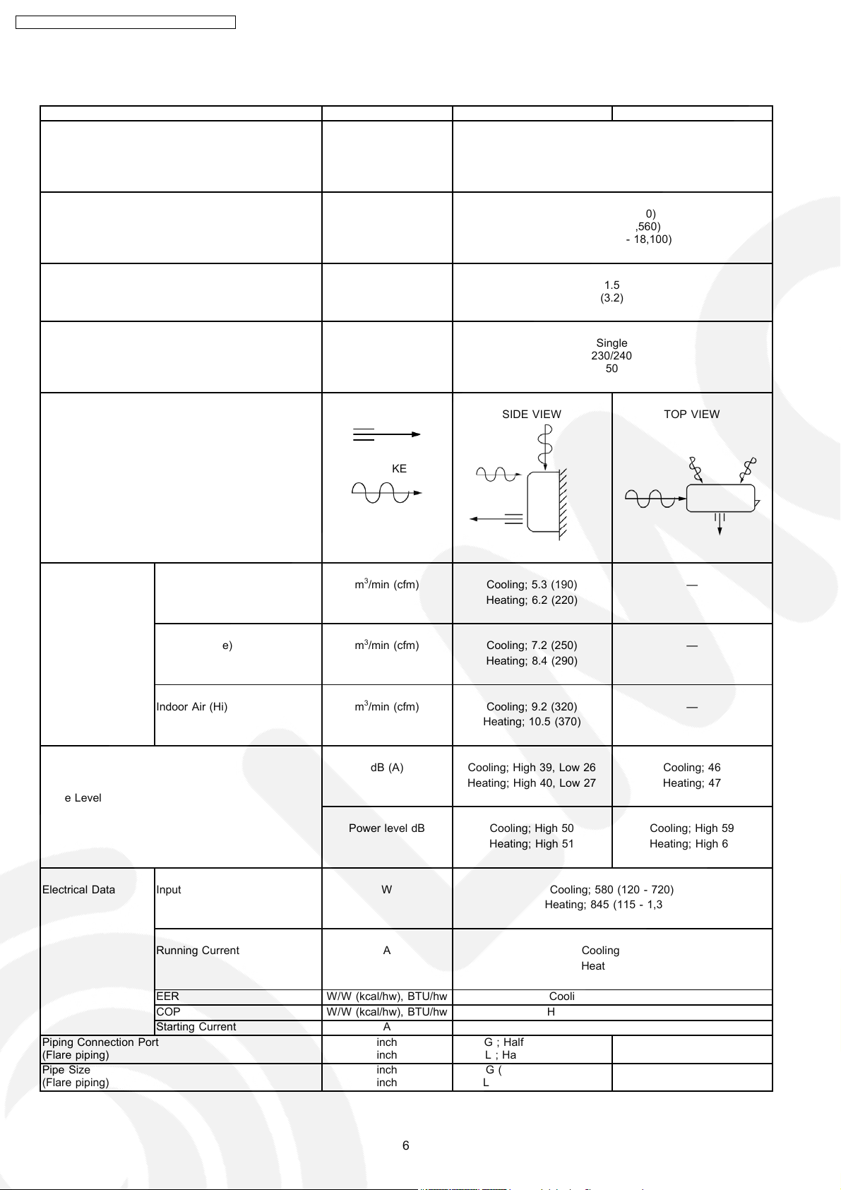
3 Product Specifications
Unit CS-TE9DKE CU-TE9DKE
Cooling Capacity kW
kcal/h
BTU/h
Heating Capacity kW
kcal/h
BTU/h
Moisture Removal l/h
Pint/h
Power Source Phase
V
Cycle
Airflow Method OUTLET
INTAKE
2.60 (0.60 - 3.00)
2,240 (520 - 2,580)
8,870 (2,050 - 10,200)
3.60 (0.60 - 5.30)
3,100 (520 - 4,560)
12,300 (2,050 - 18,100)
1.5
(3.2)
Single
230/240
50
SIDE VIEW TOP VIEW
Air Volume Indoor Air (Lo) m3/min (cfm) Cooling; 5.3 (190) —
Heating; 6.2 (220)
Indoor Air (Me) m3/min (cfm) Cooling; 7.2 (250) —
Heating; 8.4 (290)
Indoor Air (Hi) m3/min (cfm) Cooling; 9.2 (320) —
Heating; 10.5 (370)
dB (A) Cooling; High 39, Low 26 Cooling; 46
Heating; High 40, Low 27 Heating; 47
Noise Level
Power level dB Cooling; High 50 Cooling; High 59
Heating; High 51 Heating; High 60
Electrical Data Input W Cooling; 580 (120 - 720)
Heating; 845 (115 - 1,360)
Running Current A Cooling; 2.7
Heating; 3.9
Piping Connection Port
(Flare piping)
Pipe Size
(Flare piping)
EER W/W (kcal/hw), BTU/hw Cooling; 4.48(3.86), 15.3
COP W/W (kcal/hw), BTU/hw Heating; 4.26 (3.67), 14.5
Starting Current A 3.9
inch
inch
inch
inch
G ; Half Union 3/8”
L ; Half Union 1/4”
G (gas side) ; 3/8”
L (liquid side) ; 1/4”
G ; 3-way valve 3/8”
L ; 2-way valve 1/4”
G (gas side) ; 3/8”
L (liquid side) ; 1/4”
6
CS-TE9DKE CU-TE9DKE / CS-TE 12DKE CU-TE12D KE
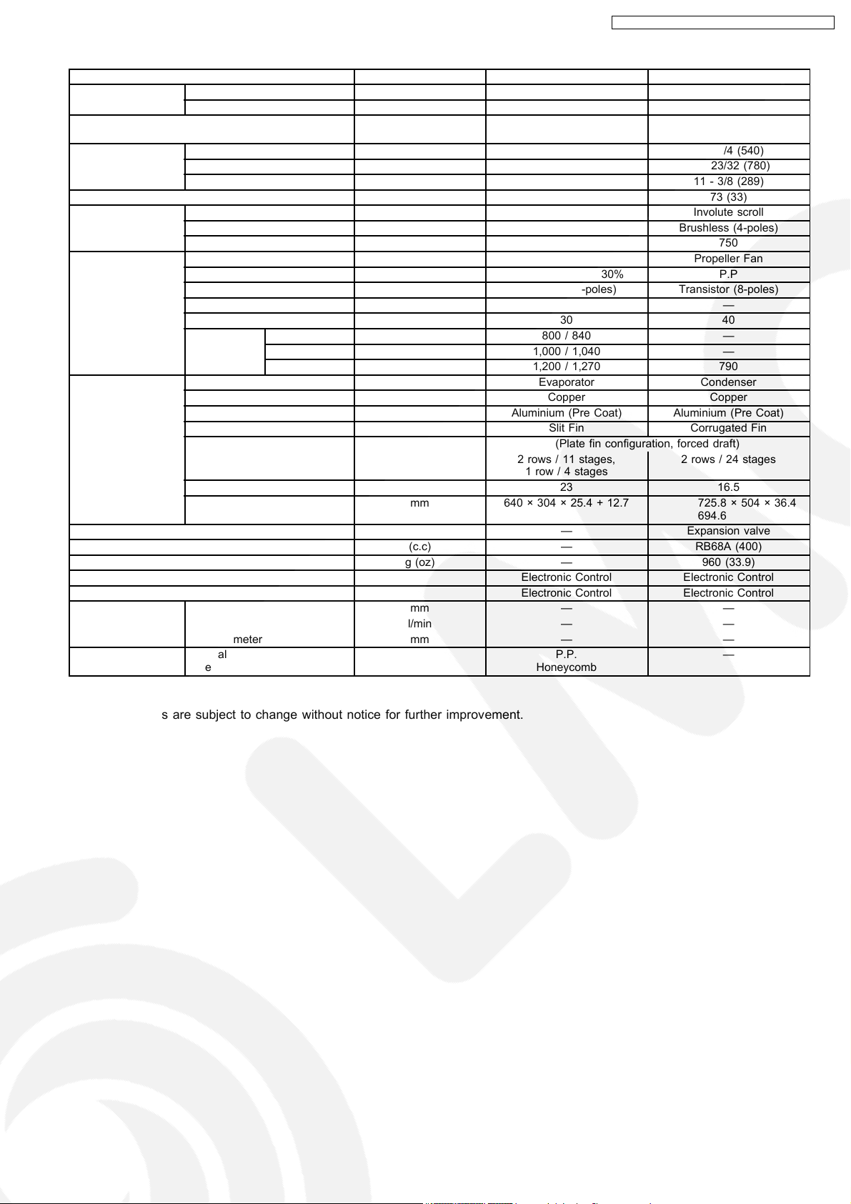
Unit CS-TE9DKE CU-TE9DKE
Drain
Hose
Power Cord Length
Number of core-wire
Dimensions Height inch (mm) 11 - 23/32 (298) 21 - 1/4 (540)
Net Weight lb (kg) 18 (8) 73 (33)
Compressor Type — Involute scroll
Air Circulation Type Cross-flow Fan Propeller Fan
Heat Exchanger Description Evaporator Condenser
Refrigerant Control Device — Expansion valve
Refrigeration Oil (c.c) — RB68A (400)
Refrigerant (R410A) g (oz) — 960 (33.9)
Thermostat Electronic Control Electronic Control
Protection Device Electronic Control Electronic Control
Capillary Tube Flow Rate l/min — —
Air Filter Material
Inner diameter mm 16 —
Length m 0.65 —
3-core wires × 1.0 mm
Width inch (mm) 31 - 15/32 (799) 30 - 23/32 (780)
Depth inch (mm) 5 - 15/32 (139) 11 - 3/8 (289)
Motor Type — Brushless (4-poles)
Rated Output W — 750
Material AS + Glass Fiber 30% P.P
Motor Type Transistor (8-poles) Transistor (8-poles)
Input W — —
Rate Output W 30 40
Fan Speed Lo (Cool/Heat) rpm 800 / 840 —
Me (Cool/Heat) rpm 1,000 / 1,040 —
Hi (Cool/Heat) rpm 1,200 / 1,270 790
Tube material Copper Copper
Fin material Aluminium (Pre Coat) Aluminium (Pre Coat)
Fin Type Slit Fin Corrugated Fin
Row / Stage (Plate fin configuration, forced draft)
FPI 23 16.5
Size (W × H × L) mm 640 × 304 × 25.4 + 12.7 725.8
Length mm — —
Inner Diameter mm — —
Style
2.0 m
2 rows / 11 stages,
1 row / 4 stages
P.P.
Honeycomb
2
—
—
2 rows / 24 stages
× 504 × 36.4
694.6
—
•
•
Specifications are subject to change without notice for further improvement.
• •
7
CS-TE9DKE CU-TE9DKE / CS-TE 12DKE CU-TE12D KE
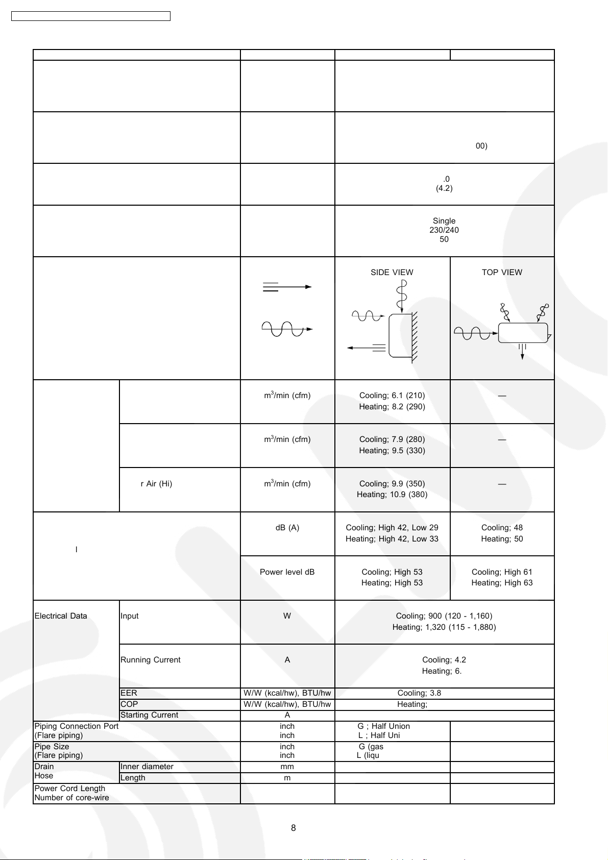
Unit CS-TE12DKE CU-TE12DKE
Cooling Capacity kW
kcal/h
BTU/h
Heating Capacity kW
kcal/h
BTU/h
Moisture Removal l/h
Pint/h
Power Source Phase
V
Cycle
Airflow Method OUTLET
INTAKE
3.50 (0.60 - 4.00)
3,010 (520 - 3,440)
11,950 (2,050 - 13,600)
4.80 (0.60 - 6.50)
4,130 (520 - 5,590)
16,400 (2,050 - 22,200)
2.0
(4.2)
Single
230/240
50
SIDE VIEW TOP VIEW
Air Volume Indoor Air (Lo) m3/min (cfm) Cooling; 6.1 (210) —
Heating; 8.2 (290)
Indoor Air (Me) m3/min (cfm) Cooling; 7.9 (280) —
Heating; 9.5 (330)
Indoor Air (Hi) m3/min (cfm) Cooling; 9.9 (350) —
Heating; 10.9 (380)
dB (A) Cooling; High 42, Low 29 Cooling; 48
Heating; High 42, Low 33 Heating; 50
Noise Level
Power level dB Cooling; High 53 Cooling; High 61
Heating; High 53 Heating; High 63
Electrical Data Input W Cooling; 900 (120 - 1,160)
Heating; 1,320 (115 - 1,880)
Running Current A Cooling; 4.2
Heating; 6.2
Piping Connection Port
(Flare piping)
Pipe Size
(Flare piping)
Drain
Hose
Power Cord Length
Number of core-wire
EER W/W (kcal/hw), BTU/hw Cooling; 3.89 (3.34), 13.3
COP W/W (kcal/hw), BTU/hw Heating; 3.64 (3.13), 12.4
Starting Current A 6.2
inch
inch
inch
inch
G ; Half Union 1/2”
L ; Half Union 1/4”
G (gas side) ; 1/2”
L (liquid side) ; 1/4”
G ; 3-way valve 1/2”
L ; 2-way valve 1/4”
G (gas side) ; 1/2”
L (liquid side) ; 1/4”
Inner diameter mm 16 —
Length m 0.65 —
3-core wires × 1.0 mm
2.0 m
2
8
—
—
CS-TE9DKE CU-TE9DKE / CS-TE 12DKE CU-TE12D KE
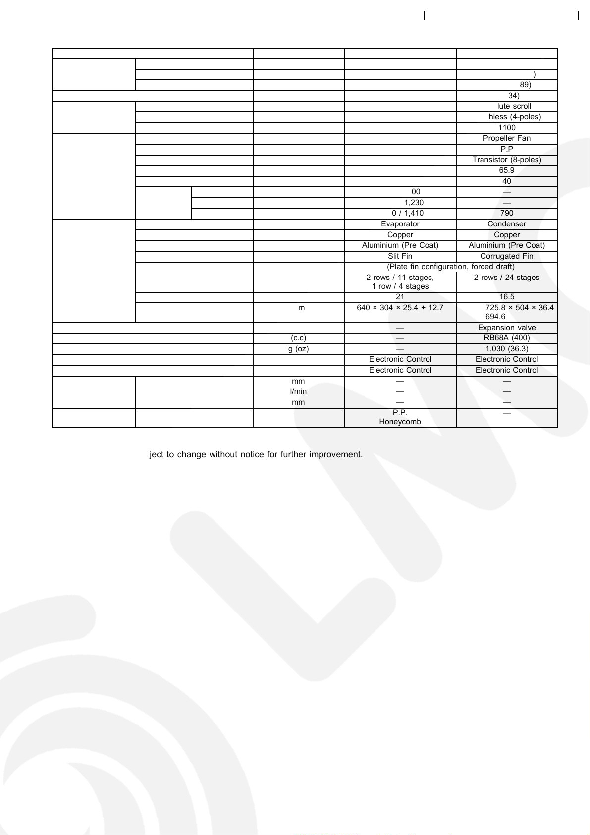
Unit CS-TE12DKE CU-TE12DKE
Dimensions Height inch (mm) 11 - 23/32 (298) 21 - 1/4 (540)
Width inch (mm) 31 - 15/32 (799) 30 - 23/32 (780)
Depth inch (mm) 5 - 15/32 (139) 11 - 3/8 (289)
Net Weight lb (kg) 18 (8) 75 (34)
Compressor Type — Involute scroll
Motor Type — Brushless (4-poles)
Rated Output W — 1100
Air Circulation Type Cross-flow Fan Propeller Fan
Material AS + Glass Fiber 30% P.P
Motor Type Transistor (8-poles) Transistor (8-poles)
Input W — 65.9
Rate Output W 30 40
Fan Speed Lo (Cool/Heat) rpm 880 / 1,100 —
Me (Cool/Heat) rpm 1,100 / 1,230 —
Hi (Cool/Heat) rpm 1,310 / 1,410 790
Heat Exchanger Description Evaporator Condenser
Tube material Copper Copper
Fin material Aluminium (Pre Coat) Aluminium (Pre Coat)
Fin Type Slit Fin Corrugated Fin
Row / Stage (Plate fin configuration, forced draft)
2 rows / 11 stages,
1 row / 4 stages
FPI 21 16.5
Size (W × H × L) mm 640 × 304 × 25.4 + 12.7 725.8
Refrigerant Control Device — Expansion valve
Refrigeration Oil (c.c) — RB68A (400)
Refrigerant (R410A) g (oz) — 1,030 (36.3)
Thermostat Electronic Control Electronic Control
Protection Device Electronic Control Electronic Control
Length mm — —
Capillary Tube Flow Rate l/min — —
Inner Diameter mm — —
Air Filter Material
Style
P.P.
Honeycomb
2 rows / 24 stages
× 504 × 36.4
694.6
—
•
•
Specifications are subject to change without notice for further improvement.
• •
9

CS-TE9DKE CU-TE9DKE / CS-TE 12DKE CU-TE12D KE
4 Dimensions
4.1. Indoor Unit
10
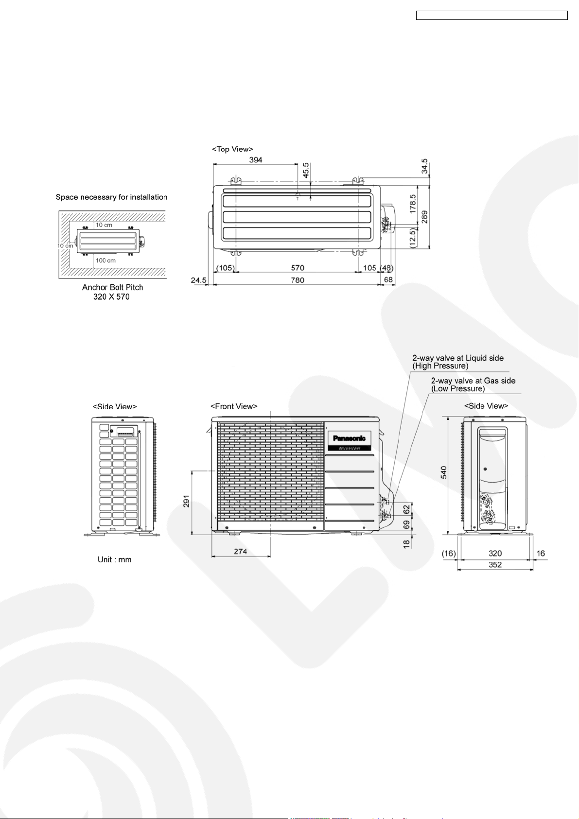
4.2. Outdoor Unit
CS-TE9DKE CU-TE9DKE / CS-TE 12DKE CU-TE12D KE
11
CS-TE9DKE CU-TE9DKE / CS-TE 12DKE CU-TE12D KE
5 Refrigeration Cycle Diagram
12
6 Block Diagram
CS-TE9DKE CU-TE9DKE / CS-TE 12DKE CU-TE12D KE
13
CS-TE9DKE CU-TE9DKE / CS-TE 12DKE CU-TE12D KE
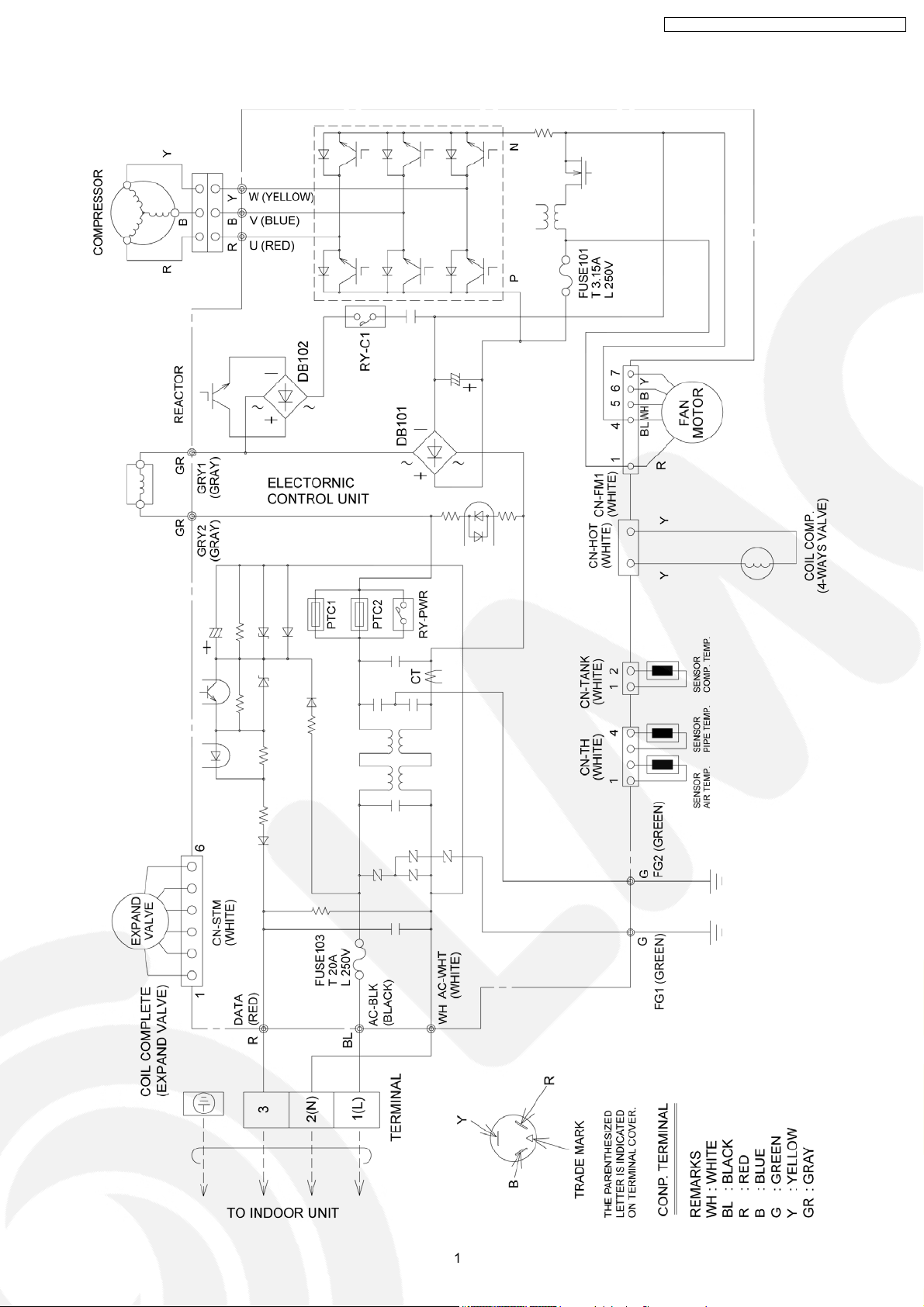
7 Wiring Diagram
7.1. CS-TE9DTE / CS-TE12DKE
14
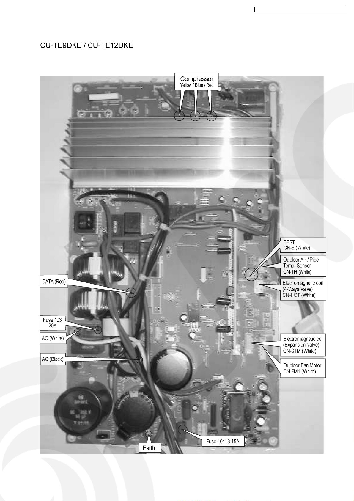
7.2. CU-TE9DKE / CU-TE12DKE
CS-TE9DKE CU-TE9DKE / CS-TE 12DKE CU-TE12D KE
15
CS-TE9DKE CU-TE9DKE / CS-TE 12DKE CU-TE12D KE
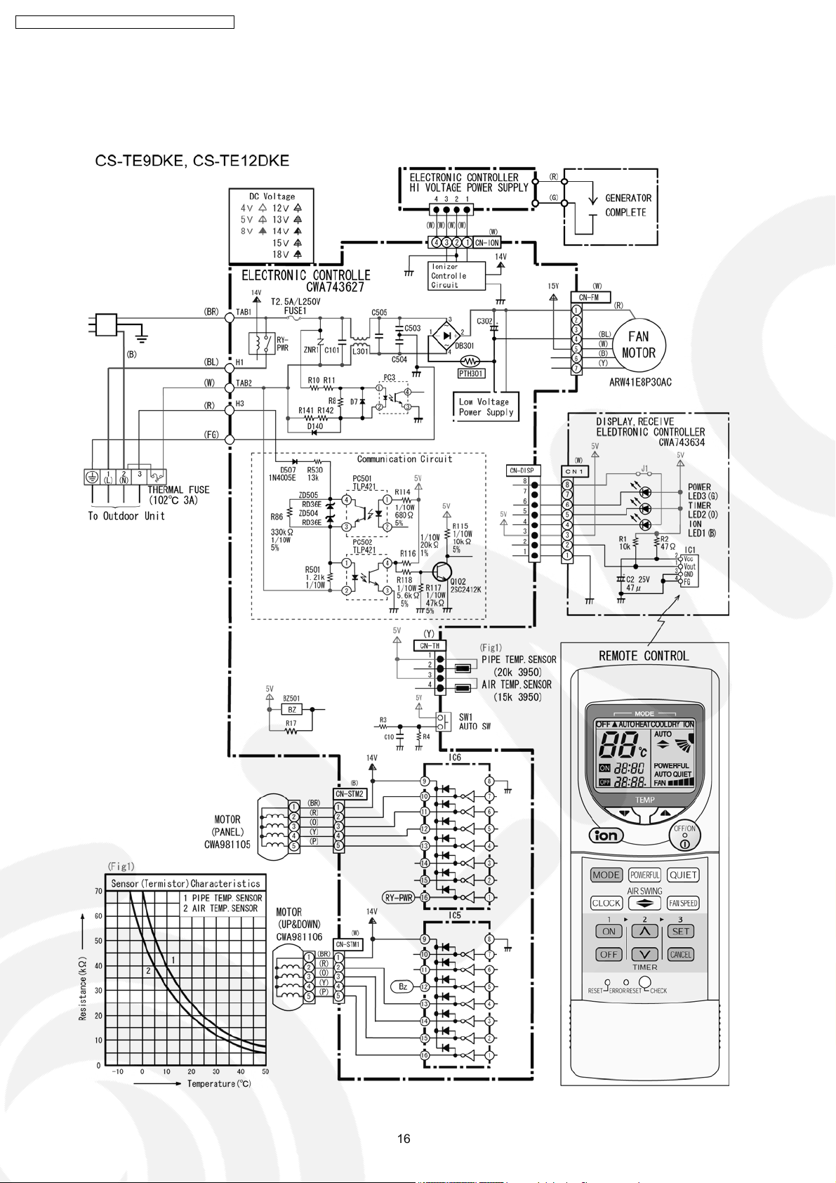
8 Electronic Circuit Diagram
8.1. Indoor Unit / Remote Controller
16
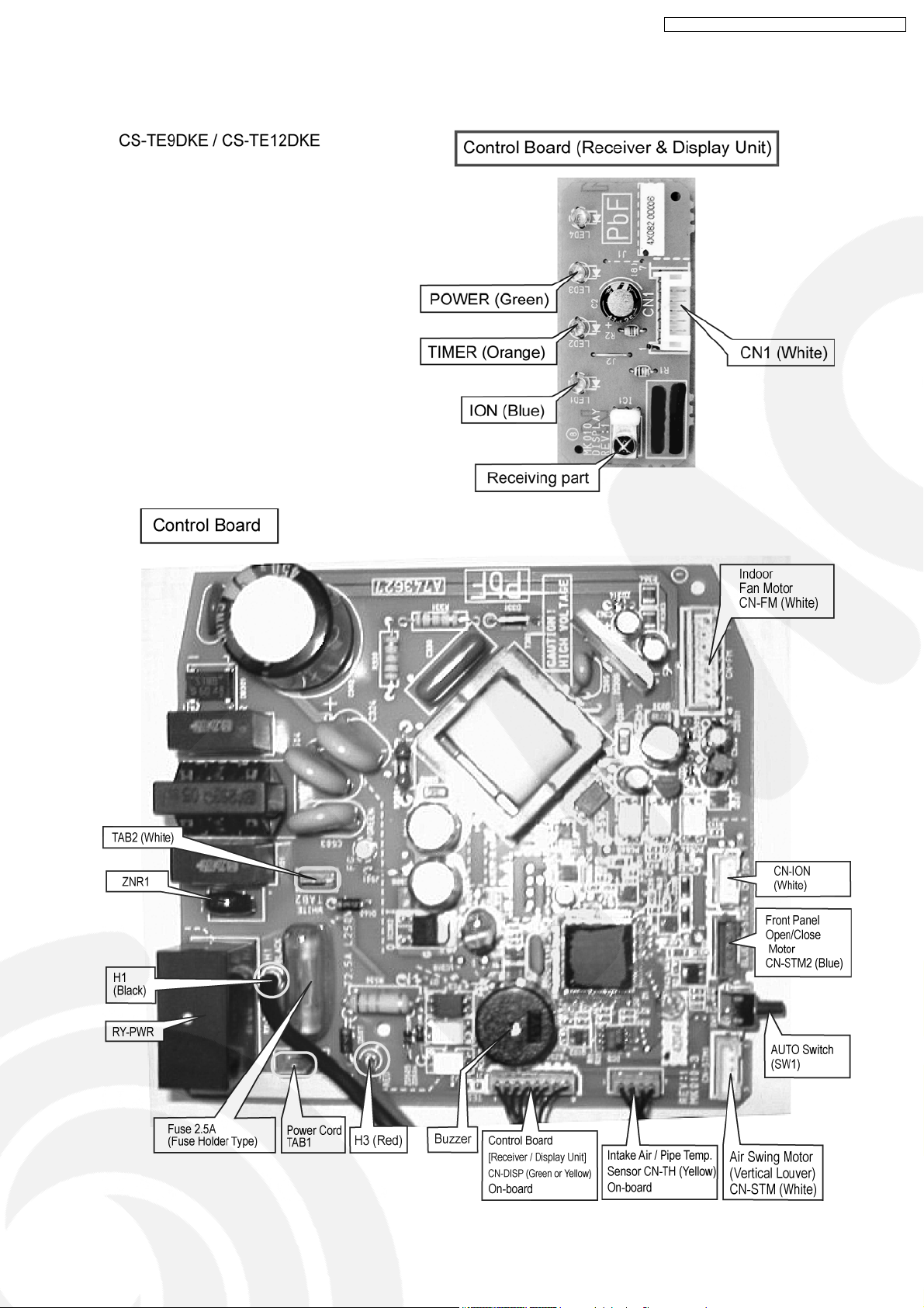
8.1.1. Printed Circuit Board
CS-TE9DKE CU-TE9DKE / CS-TE 12DKE CU-TE12D KE
17
CS-TE9DKE CU-TE9DKE / CS-TE 12DKE CU-TE12D KE
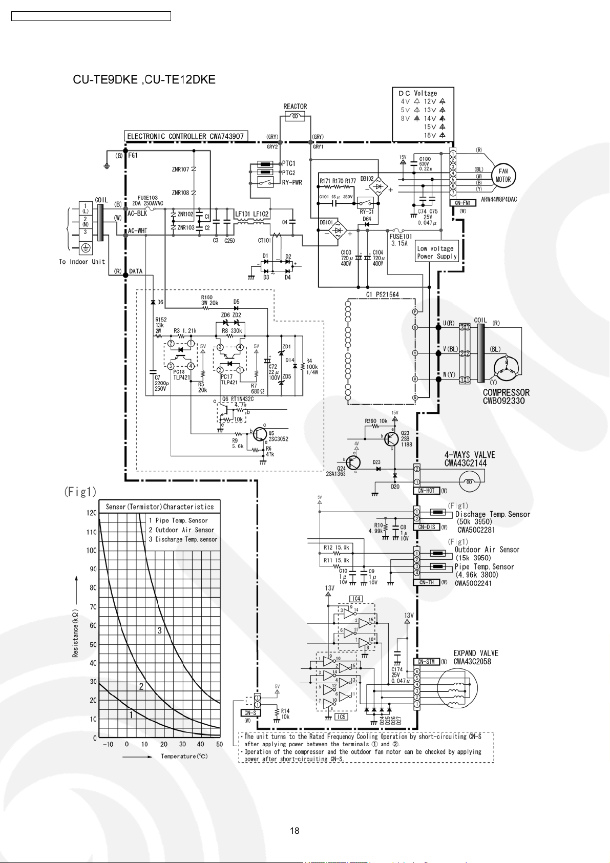
8.2. Outdoor Unit
18
8.2.1. Printed Circuit Board
CS-TE9DKE CU-TE9DKE / CS-TE 12DKE CU-TE12D KE
19
CS-TE9DKE CU-TE9DKE / CS-TE 12DKE CU-TE12D KE
9 Operation Details
9.1. BASIC FUNCTION
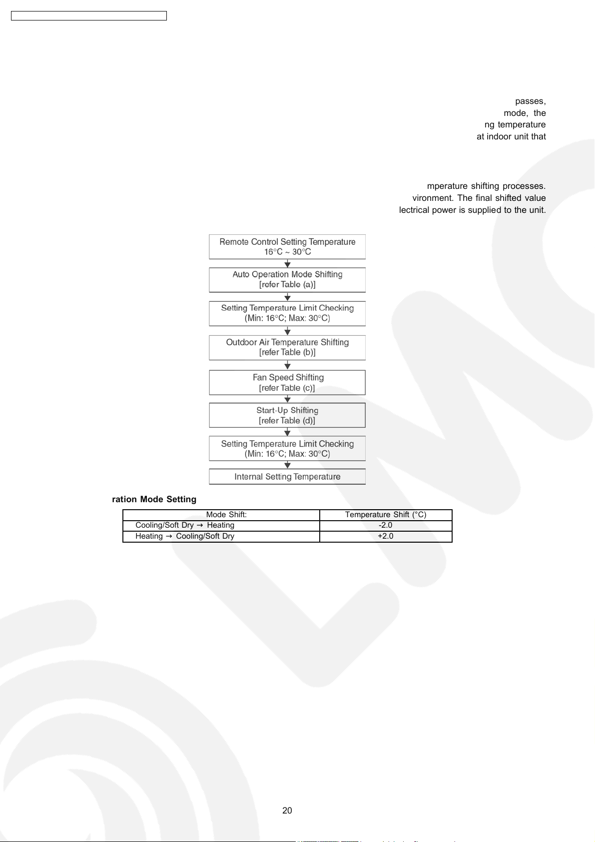
Inverter control, which equipped with a microcomputer in determining the most suitable operating mode as time passes,
automatically adjusts output power for maximum comfort always. In order to achieve the suitable operating mode, the
microcomputer maintains the set temperature by measuring the temperature of the environment and performing temperature
shifting. The compressor at outdoor unit is operating following the frequency instructed by the microcomputer at indoor unit that
judging the condition according to internal setting temperature and intake air temperature.
9.1.1. Internal Setting Temperature
Once the operation starts, remote control setting temperature will be taken as base value for temperature shifting processes.
These shifting processes are depending on the air conditio ner settings and the operation environment. The final shifted value
will be used as internal setting temperature and it is updated continuously whenever the electrical power is supplied to the unit.
Table (a): Auto Operation Mode Setting
Cooling/Soft Dry→Heating -2.0
Heating→Cooling/Soft Dry +2.0
Mode Shift: Temperature Shift (°C)
20
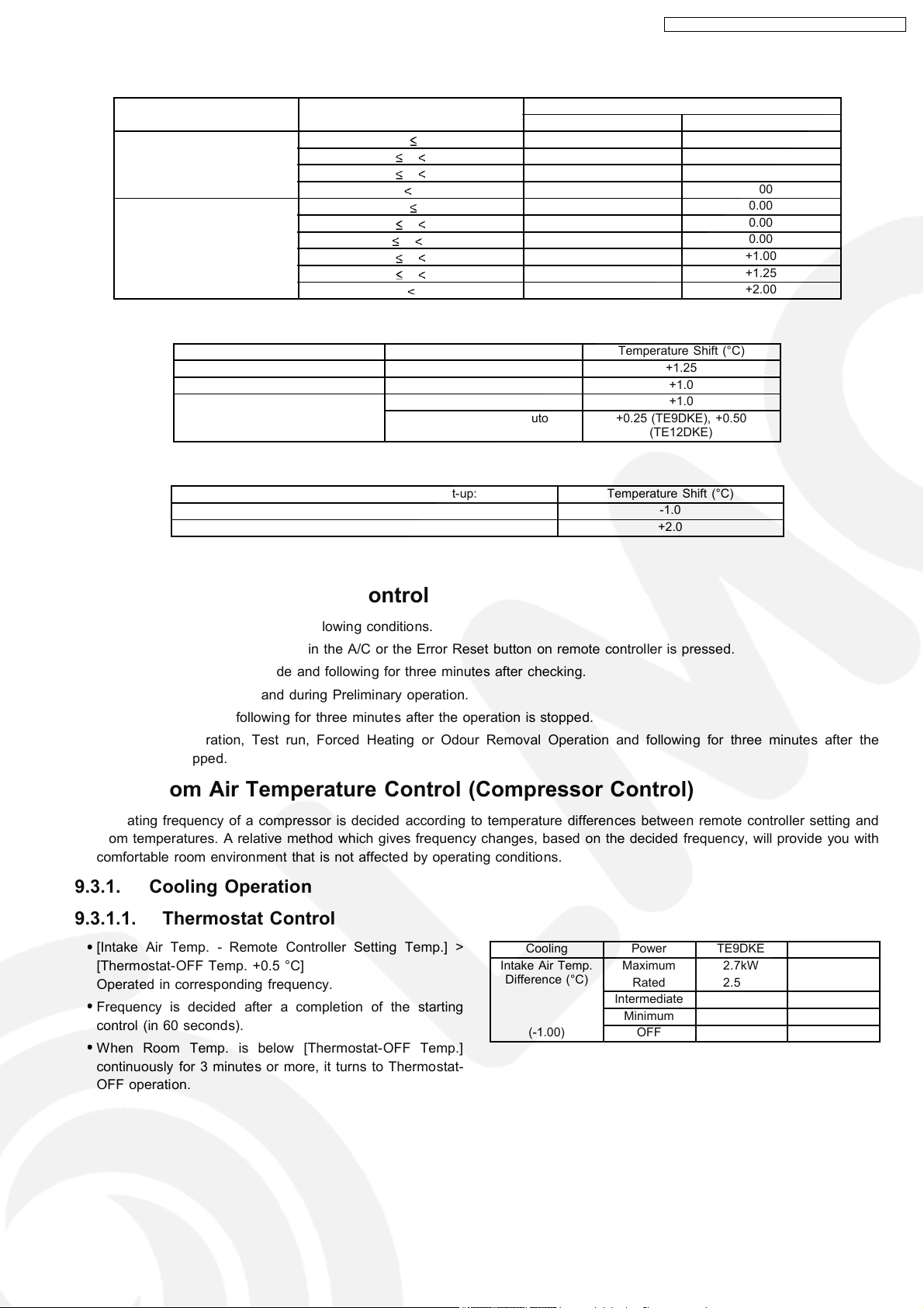
Table (b): Outdoor Air Temperature Shifting
Mode: Outdoor Temperature, X (°C): Temperature Shift (°C)
Cooling/Soft Dry 38 X 0.00 0.00
Heating 21 X 0.00 0.00
Table (c): Fan Speed Shifting
Mode: Fan Speed: Temperature Shift (°C)
Cooling All +1.25
Soft Dry All +1.0
Heating Lo +1.0
Table (d): Start-Up Shifting
Mode within 60 Minutes from Start-up: Temperature Shift (°C)
Cooling/Soft Dry -1.0
Heating +2.0
CS-TE9DKE CU-TE9DKE / CS-TE 12DKE CU-TE12D KE
TE9DKE TE12DKE
30 X 38 0.00 0.00
23 X 30 0.00 0.00
X 23 0.00 0.00
17 X 21 0.00 0.00
9 X 17 0.00 0.00
5 X 9 +0.50 +1.00
1 X 5 +1.00 +1.25
X 1 +1.50 +2.00
Hi, Me-, Me, Me+, Auto +0.25 (TE9DKE), +0.50
(TE12DKE)
9.2. Indoor Power Relay Control
The Power Relay turns on under the following conditions.
1. For three minutes, when plugged in the A/C or the Error Reset button on remote controller is pressed.
2. During Installation Check Mode and following for three minutes after checking.
3. During On-timer sampling and during Preliminary operation.
4. During Operation and following for three minutes after the operation is stopped.
5. During Auto Operation, Test run, Forced Heating or Odour Removal Operation and following for three minutes after the
operation is stopped.
9.3. Room Air Temperature Control (Compressor Control)
Operating frequency of a compressor is decided according to temperature differences between remote controller setting and
room temperatures. A relative method which gives frequency changes, based on the decided frequency, will provide you with
comfortable room environment that is not affected by operating conditions.
9.3.1. Cooling Operation
9.3.1.1. Thermostat Control
•
•
[Intake Air Temp. - Remote Controller Setting Temp.] >
• •
[Thermostat-OFF Temp. +0.5 °C]
Operated in corresponding frequency.
•
•
Frequency is decided after a completion of the starting
• •
control (in 60 seconds).
•
•
When Room Temp. is below [Thermostat-OFF Temp.]
• •
continuously for 3 minutes or more, it turns to Thermostat-
OFF operation.
Cooling Power TE9DKE TE12DKE
Intake Air Temp.
Difference (°C)
(-1.00) OFF —- —-
Maximum 2.7kW 4.0kW
Rated 2.5kW 3.6kW
Intermediate ~ ~
Minimum 0.8kW 0.8kW
21
CS-TE9DKE CU-TE9DKE / CS-TE 12DKE CU-TE12D KE
9.3.2. Dry Operation
9.3.2.1. Thermostat Control
•
•
[Intake Air Temp. - Remote Controller Setting Temp.] >
• •
[Thermostat-OFF Temp. +0.5 °C]
Operated in corresponding frequency.
•
•
Frequency is decided after a completion of the starting
• •
control (in 60 seconds).
•
•
When Room Temp. is below [Thermostat-OFF Temp.]
• •
continuously for 3 minutes or more, it turns to ThermostatOFF operation.
•
•
When room temperature almost comes to Thermostat-OFF
• •
Temp., the operation turns to the Minimum power & fan
speed: SSLo.
Dry Power TE9DKE TE12DKE
Intake Air Temp.
Difference (°C)
(-2.50) OFF — —
Maximum 2.7kW 4.0kW
Rated 2.5kW 3.6kW
Intermediate ~ ~
Minimum 0.8kW 0.8kW
9.3.3. Heating Operation
9.3.3.1. Thermostat Control
•
•
[Intake Air Temp. - Remote Controller Setting Temp.] >
• •
[Thermostat-OFF Temp. +0.5 °C]
Operated in corresponding frequency.
•
•
Frequency is decided after a completion of starting control
• •
(in 60 seconds).
•
•
When Room Temp. is below Thermostat-OFF Temp.
• •
continuously for 3 minutes or more, it turns to Thermostat-
OFF operation.
•
•
When room temperature almost comes to Thermostat-OFF
• •
Temp., the operation turns to the Maximum power.
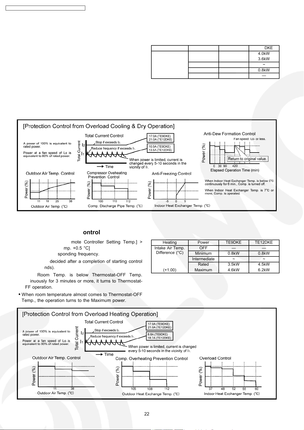
Heating Power TE9DKE TE12DKE
Intake Air Temp.
Difference (°C)
(+1.00) Maximum 4.6kW 6.2kW
OFF — —
Minimum 0.8kW 0.8kW
Intermediate ~ ~
Rated 3.5kW 4.5kW
22
CS-TE9DKE CU-TE9DKE / CS-TE 12DKE CU-TE12D KE
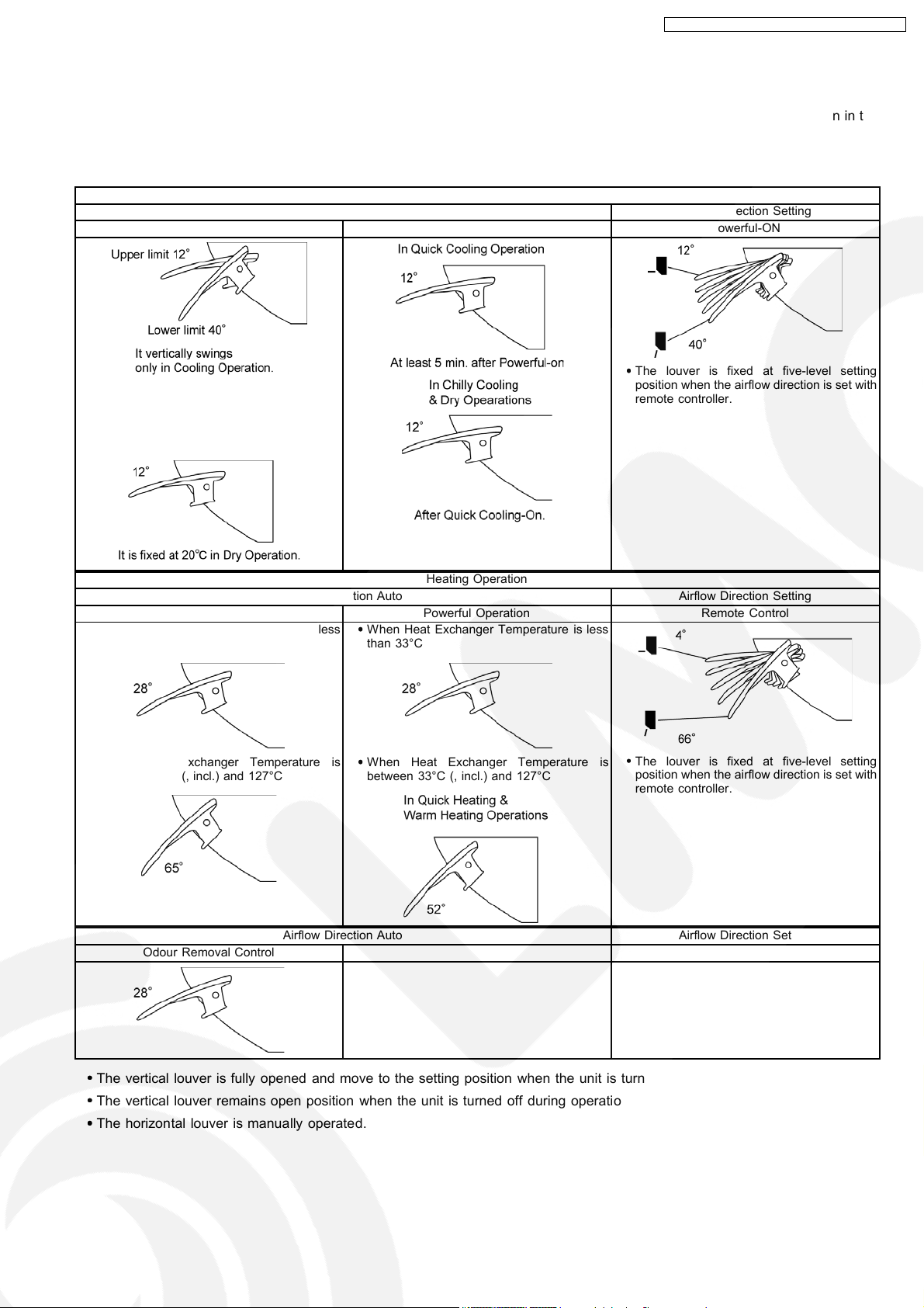
9.4. Airflow Direction Control
Vertical louver is controlled with Vertical Airflow Direction button on remote controller and by operation conditions, as shown in the
table below.
9.4.1. Vertical Airflow Louver Angle
Cooling and Dry Operations
Airflow Direction Auto Airflow Direction Setting
Manual Operation Vertical Auto Operation Powerful-ON
•
•
The louver is fixed at five-level setting
• •
•
•
It swings when airflow direction is set with
• •
remote controller.
•
•
It does not swing while indoor fan is
• •
stopped. (It is fixed at the upper limit.).
position when the airflow direction is set with
remote controller.
Heating Operation
Airflow Direction Auto Airflow Direction Setting
Fixed by Heat Exchanger Temperature Powerful Operation Remote Control
•
•
When Heat Exchanger Temperature is less
• •
than 33°C
•
•
When Heat Exchanger Temperature is
• •
between 33°C (, incl.) and 127°C
Airflow Direction Auto Airflow Direction Setting
Odour Removal Control
•
•
When Heat Exchanger Temperature is less
• •
than 33°C
•
•
When Heat Exchanger Temperature is
• •
between 33°C (, incl.) and 127°C
•
•
The louver is fixed at five-level setting
• •
position when the airflow direction is set with
remote controller.
•
•
The vertical louver is fully opened and move to the setting position when the unit is turned on with the remote controller.
• •
•
•
The vertical louver remains open position when the unit is turned off during operation.
• •
•
•
The horizontal louver is manually operated.
• •
23
CS-TE9DKE CU-TE9DKE / CS-TE 12DKE CU-TE12D KE
9.5. Quiet operation (Cooling Mode / Cooling area of Dry Mode)
A. Purpose
To provide quiet cooling operation compare to normal operation.
B. Control condition
a. Quiet operation start condition
•
•
When “quiet” button at remote control is pressed.
• •
Quiet LED illuminates.
b. Quiet operation stop condition
1. When one of the following conditions is satisfied, quiet operation stops:
a. Powerful button is pressed.
b. Stop by OFF/ON switch.
c. Timer “off” activates.
d. When change mode to ION only mode.
2. When quiet operation is stopped, operation is shifted to normal operation with previous setting.
3. When fan speed is changed, quiet operation is shifted to quiet operation of the new fan speed.
4. When operation mode is changed, quiet operation is shifted to quiet operation of the new mode, except ION only mode.
5. During quiet operation, if timer “on” activates, quiet operation maintains.
6. After off, when on back, quiet operation is not memorised.
C. Control contents
1. Fan speed is changed from normal setting to quiet setting of respective fan speed.
This is to reduce sound of Hi, Me, Lo for 3dB.
2. Fan speed for quiet operation is -100 rpm from setting fan speed.
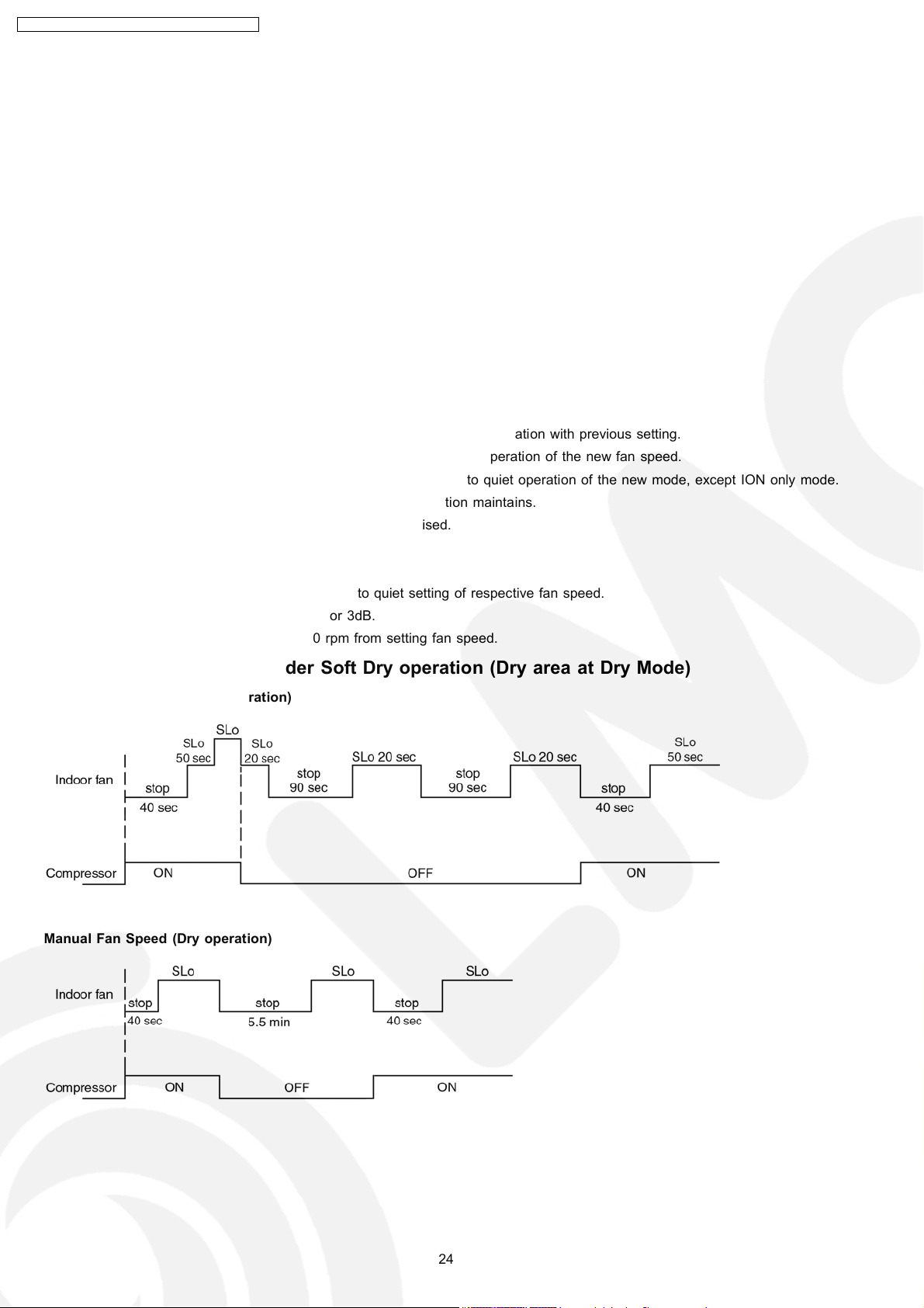
9.5.1. Quiet operation under Soft Dry operation (Dry area at Dry Mode)
Automatic Fan Speed (Dry operation)
Manual Fan Speed (Dry operation)
24
 Loading...