


CW-XC183HU

INSTALLATION AND
OPERATING INSTRUCTIONS
Room Air Conditioner
Models: CW-XC183HU
CW-XC243HU
Please read these operating instructions thoroughly
before using your air conditioner and keep for future
reference.
For assistance, please call: 1-800-211-PANA(7262) or
Register your product at : http://www.panasonic.com/register
R
2
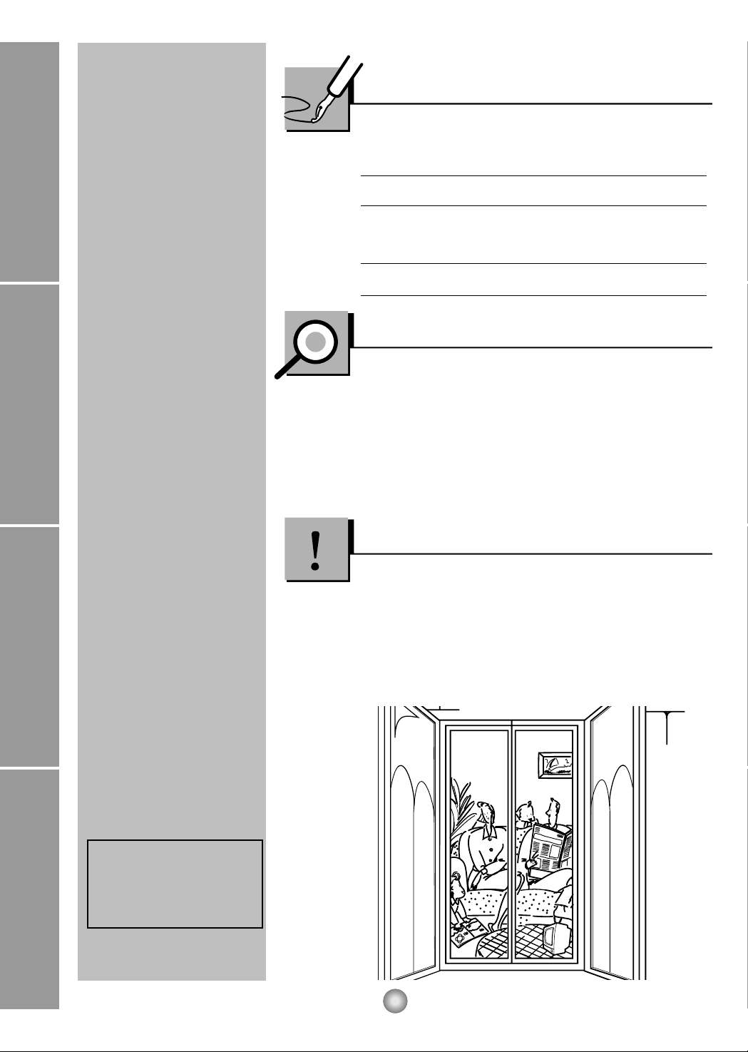
Safety Precautions
About the Controls on the Air Conditioner
Features and Installation
Before you call for service...
FOR YOUR RECORDS
Staple your receipt to this page in case you need it later.
Write down the model and serial numbers here:
Model #
Serial #
You can find them on a label on the side of each unit.
Dealer's Name
Date Purchased
Inside you will find many helpful hints on how to use and
maintain your air conditioner properly. Just a little preventive
care on your part can save you a great deal of time and
money over the life of your air conditioner.
You'll find many answers to common problems in the chart
of troubleshooting tips. If you review our chart of
Troubleshooting Tips first, you may not need to call for
service at all.
READ THIS MANUAL
CAUTION
• Contact the authorized Service technician for repair or
maintenance of this unit.
• The air conditioner is not intended for use by young
children or infirm persons without supervision.
• Young children should be supervised to ensure that they
do not play with the air conditioner.
Safety Precautions
Safety Precautions.............3
About the Controls on
the Air Conditioner
Controls..............................5
Ventilation ..........................6
Air Direction........................6
How to Secure Drain Pipe
....6
Care and Maintenance
Air Filter Cleaning...............7
How to Insert Batteries.......7
Features
Features.............................8
Installation
How to Install the Unit........9
Window Requirements.......9
Installation Kit Contents ...10
Suggested Tool
Requirements...................11
Cabinet Installation...........12
Electrical Data..................14
Electrical Safety ...............14
Before you call for
service...
Normal Operation.............15
Abnormal Operation.........15
WARNING
3
Safety Precautions
Safety Precautions
To prevent injury to the user or other people and property damage, the following instructions must be
followed.
■ Incorrect operation due to ignoring of instruction will cause harm or damage. The seriousness is classified
by the following indications.
■ Meanings of symbols used in this manual are as shown below.
Plug in the power plug
properly.
• Otherwise, it will cause electric
shock or fire due to heat
generation.
Do not operate or stop the
unit by inserting or pulling
out the power plug.
• It will cause electric shock or fire
due to heat generation.
Do not damage or use an
unspecified power cord.
• It will cause electric shock or fire.
•
If the power cord is damaged, it must
be replaced by the manufacturer or
an authorized service center or a
similarly qualified person in order to
avoid a hazard.
Do not modify power cord
length or share the outlet
with other appliances.
• It will cause electric shock or fire
due to heat generation.
Do not operate with wet
hands or in a damp
environment.
• It will cause electric shock.
Do not direct air flow at room
occupants.
• This could damage your health.
WARNING : This symbol indicates the possibility of death or serious injury.
CAUTION
:
This symbol indicates the possibility of injury or damage to
property only.
Be sure not to do this.
Be sure to follow the instructions.
4
Safety Precautions
When the air filter is to be
removed, do not touch the
metal parts of the unit.
• It may cause an injury.
Do not clean the air
conditioner with water.
• Water may enter the unit and
degrade the insulation. It may
cause an electric shock.
Ventilate well when used
together with a stove, etc.
• An oxygen shortage may occur.
When the unit is to be
cleaned, switch off, and turn
off the breaker.
• Since the fan rotates at high
speed during operation, it may
cause an injury.
Do not put a pet or house
plant where it will be exposed
to direct air flow.
• This could injure the pets or
plants.
Do not use for special
purposes.
• Do not use this air conditioner to
preserve precision devices, food,
pets, plants, and art objects.
It may cause deterioration of
quality, etc.
Do not operate switches
with wet hands
.
• It may cause an electric shock.
Do not apply an insecticide
or flammable spray.
• It may cause a fire or deformation
of the cabinet.
Do not put a heater, etc.
where it is exposed to direct
air flow.
•
It may cause imperfect
combustion.
5
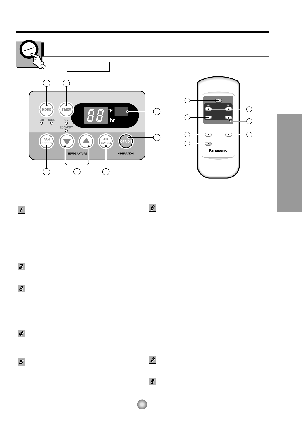
About the Controls on the Air Conditioner
62
1
8
34 7
OPERATION
TEMP
TIMER
AIR
SWING
MODE
ECONOMY
FAN SPEED
1
6
2 4
5
3
7
About the Controls on the Air Conditioner
Controls
REMOTE CONTROL
DISPLAY
OPERATION BUTTON
• To turn the air conditioner ON, push the
button. To turn the air conditioner OFF, push
the button again.
• This button takes priority over any other
buttons.
• When you first turn it on, the air conditioner is
on the High cool mode and the temp. at
72°F(22°C)
OPERATION MODE SELECTION BUTTON
Every time you push this button, it will toggle
between COOL, FAN.
ROOM TEMPERATURE SETTING BUTTON
This button can automatically control the
temperature of the room. The temperature can
be set within a range of 60°F to 86°F by 1°F.
(16°C to 30°C by 1°C)
Select the lower number for lower temperature
of the room.
FAN SPEED SELECTION BUTTONS
Every time you push this button, it is set as
follows.
{High(F3) → Low(F1) → Med(F2) → High(F3)...}.
ECONOMY
• If the switch is set to "On", the fan stops when
the compressor stops cooling. Approximately
every 3 minutes the fan will turn on and check
the room air to determine if cooling is needed.
ON/OFF TIMER BUTTON
You can set the time when the unit will turn on or turn
off automatically by pressing the timer button. If the
unit is operating, this button controls the time it will be
turned off. If the unit is off state, this button controls
the time it will start. Every time you push this button,
the remaining time will be set as follows.
- STOPPING OPERATION
•
Every time you push this button, when the air
conditioner is operating, timer is set as follows.
(1Hour → 2Hours → 3Hours → 4Hours → 5Hours →
6Hours → 7Hours → 8Hours → 9Hours → 10Hours →
11Hours → 12Hours → 0Hours → 1Hours → 2Hours → ...)
• The Setting Temperature will be raised by
2°F(1°C) 30min. later and by 2°F(1°C) after
another 30 min.
- STARTING OPERATION
•
Every time you push this button, when the air conditioner
is not operating, timer is set as follows. (1Hour → 2Hours
→ 3Hours → 4Hours → 5Hours → 6Hours → 7Hours →
8Hours → 9Hours → 10Hours → 11Hours → 12Hours →
0Hours → 1Hours → 2Hours → ...)
AIR SWING BUTTON
This button can automatically control the air
flow direction.
REMOCON SIGNAL RECEIVER
Precaution: The Remote Control unit will not function properly if strong light strikes the sensor
window of the air conditioner or if there are obstacles between the Remote Control
unit and the air conditioner.
VENTCLOSE
OPEN
Part
A
Part
B
Drain pipe
Drain cap
6
About the Controls on the Air Conditioner
Additional controls and important information.
Ventilation
The ventilation lever must be in the CLOSE position in order to maintain the best cooling conditions.
When fresh air is necessary in the room, set the ventilation lever to the OPEN position.
The damper is opened and room air is drawn out.
NOTE: Before using the ventilation feature, and prior to installing the front grille, pull down part until
level with part .
Air Direction
The vertical air direction is adjusted by rotating the
horizontal louver forward or backward manually.
The horizontal air direction is adjusted by rotating the
vertical louver right or left by Remote Controller.
The direction of air can be controlled wherever you want to cool by adjusting the horizontal louver
and the vertical louver.
• VERTICAL AIR-DIRECTION CONTROL
•
HORIZONTAL AIR-DIRECTION CONTROL
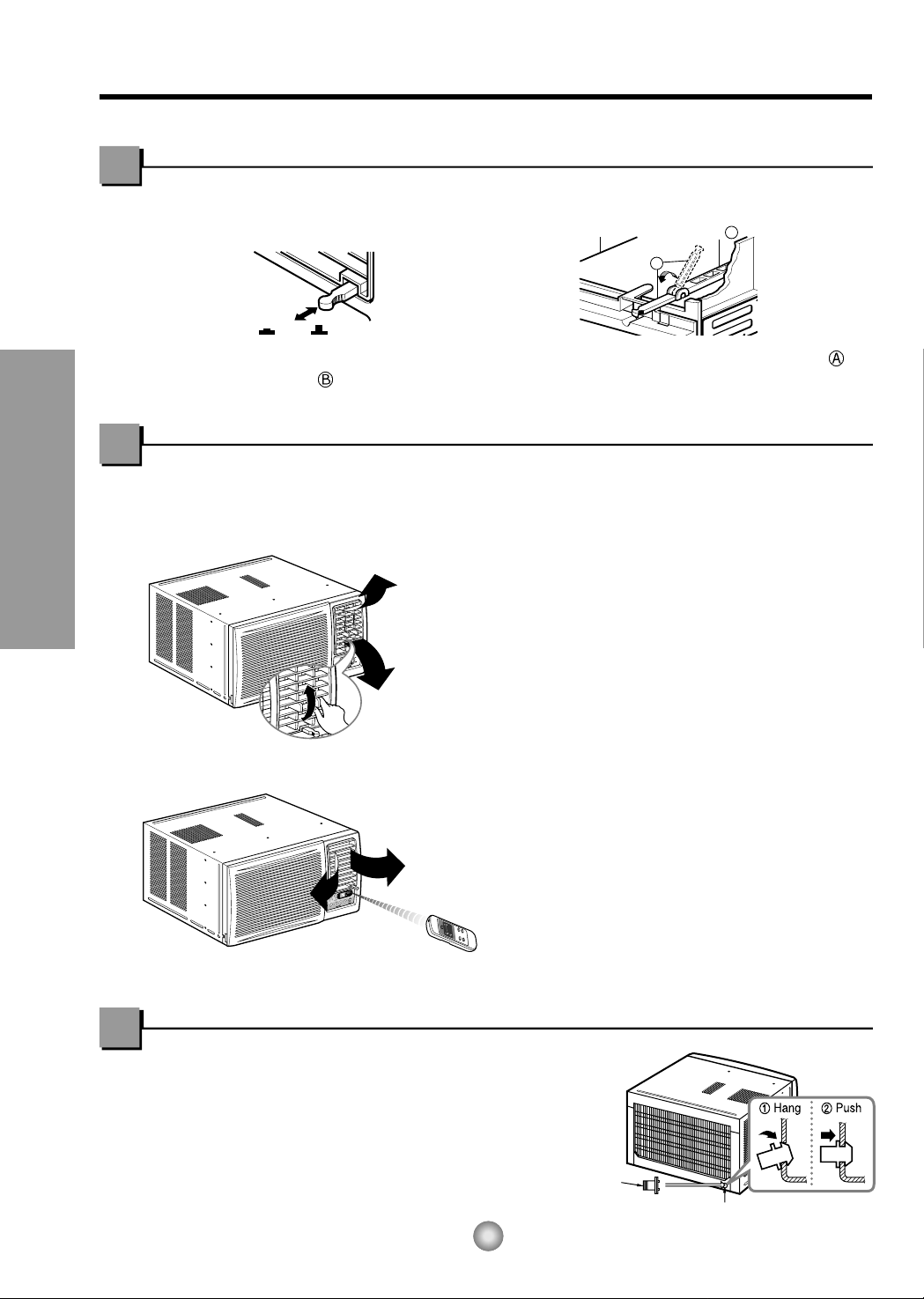
How to Secure the Drain Pipe
In humid weather, excess water may cause the BASE
PAN to overflow. To drain the water, remove the DRAIN
CAP and secure the DRAIN PIPE to the rear hole of the
BASE PAN. Press the drain pipe into the hole by pushing
down and away from the fins to avoid injury.
7
About the Controls on the Air Conditioner
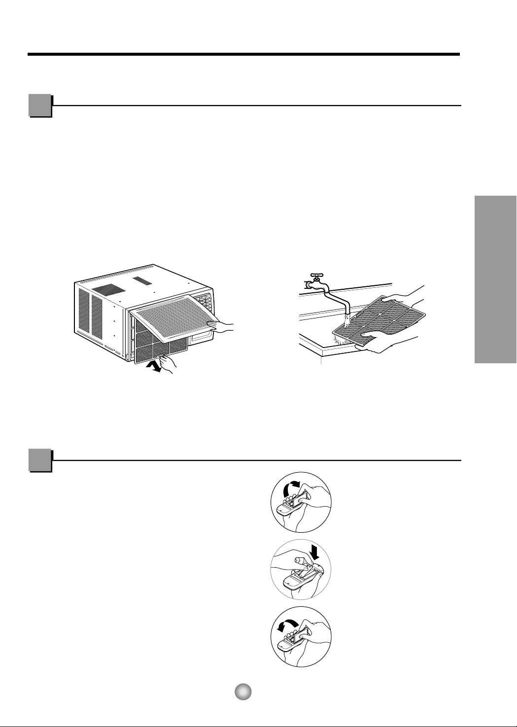
Air Filter Cleaning
The air filter behind the front grille should be checked and cleaned at least once every 2
weeks or more often if necessary.
TO REMOVE:
1. Open the inlet grille upward by pulling out the bottom of the inlet grille or downward by
pulling out the top of the inlet grille.
2. Using the tab, pull up slightly on the filter to release it and pull it down or up.
3. Clean the filter with warm, soapy water below 40°C (104°F).
4. Rinse and gently shake the water from the filter and let it dry before replacing it.
CAUTION: DO NOT operate the air conditioner without a filter because dirt and lint will
clog it and reduce performance.
Care and Maintenance
TURN THE AIR CONDITIONER OFF AND REMOVE THE PLUG FROM THE POWER OUTLET.
• Do not use
rechargeable batteries.
Such batteries
differ from standard dry
cells in shape,
dimensions, and
performance.
• Remove the batteries
from the remote
controller if the air
conditioner is not going
to be used for an
extended length of time.
How to insert batteries
1. Remove the cover from the back of the
remote
controller.
2. Insert two AAA dry cell batteries.
• Be sure that the (+) and (-) directions
are correct.
• Be sure that both batteries are new.
3. Re-attach the cover.

8
Features and Installation
Learning parts name prior to installation will help you understand the installation procedure.
Features
Features
CABINET
FRONT GRILLE
AIR FILTER
AIR INTAKE
(INLET GRILLE)
AIR DISCHARGE
HORIZONTAL AIR DEFLECTOR
(VERTICAL LOUVER)
VERTICAL AIR DEFLECTOR
(HORIZONTAL LOUVER)
EVAPORATOR
POWER CORD
BASE PAN
CONDENSER
COMPRESSOR
BRACE
CONTROL BOARD
About 1/2"
Over 20"
HEAT
RADIATION
FENCE
AWNING
INSIDE OUTSIDE
FOAM
COOLED
AIR
30-60"
Level
1/4 Bubble
26" to 41"
18" min
DESPLAZAMIENTO
ALFEZAR
EXTERIOR
PARED INTERIOR
REPISA
9
Installation
Features and Installation
How to Install the Unit
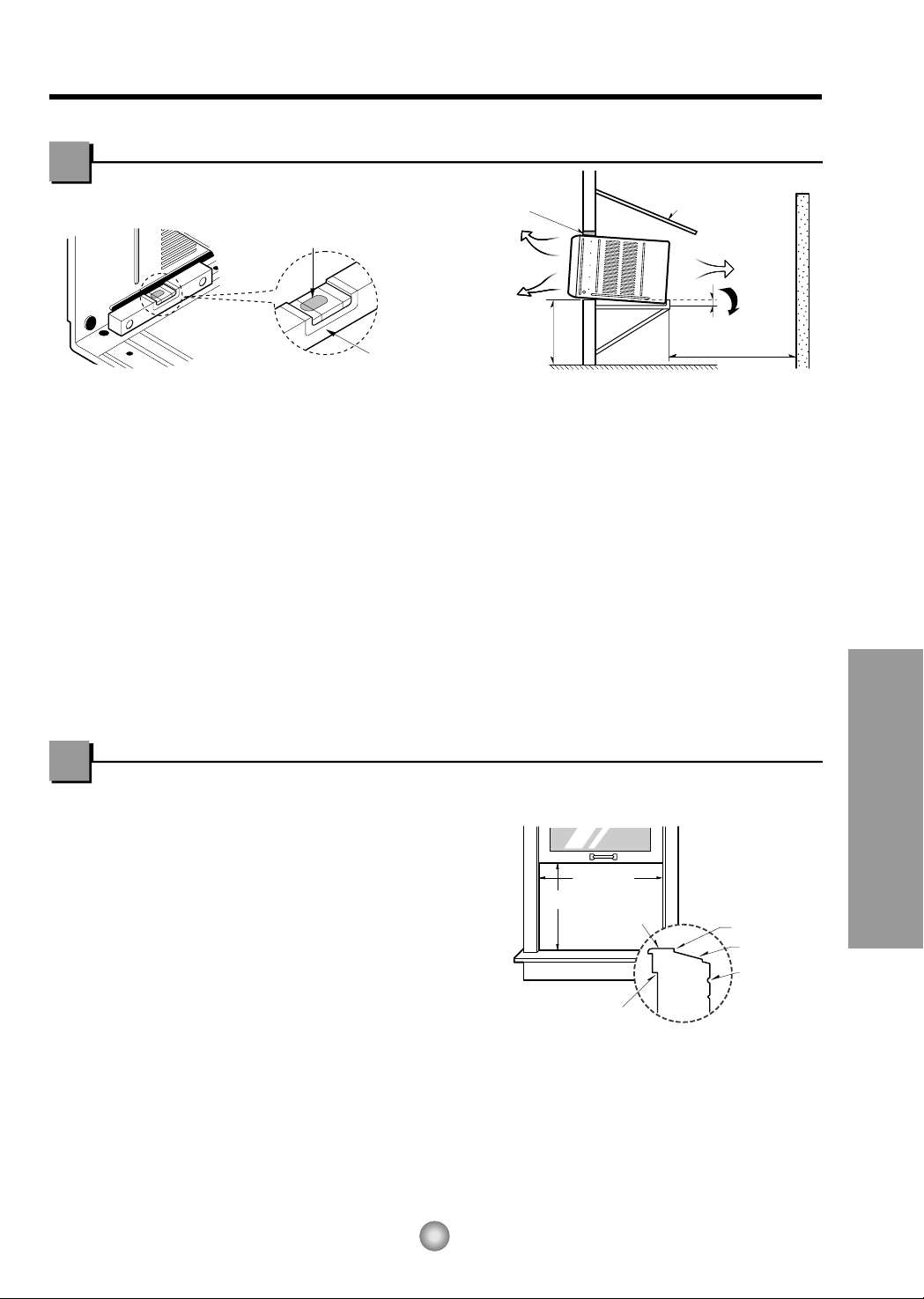
1. To avoid vibration and noise, make sure the unit is installed securely and firmly.
2. Install the unit where the sunlight does not shine directly on the unit.
If the unit receives direct sunlight, build an awning to shade the cabinet.
3. There should be no obstacle, like a fence, within 20” which might restrict heat radiation from the
condenser.
4. To prevent reducing performance, install the unit so that louvers of the cabinet are not blocked.
5. Install the unit a little obliquely outward not to avoid leaking the condensed water into the room
(about 1/2” or 1/4 bubble with level).
6. Install the unit with its bottom portion 30~60” above the floor level.
7. Stuff the foam between the top of the unit and the wall to prevent air and insects from getting into
the room.
8. The power cord must be connected to an independent circuit. The green wire must be grounded.
9. Connect the drain tube to the base pan hole in the rear side if you need to drain (consult a dealer.)
Plastic hose or equivalent may be connected to the drain tube.
NOTE: All supporting parts should be secured to firm wood, masonry, or metal.
WINDOW REQUIREMENTS
1. This unit is designed for installation in
standard double hung windows with actual
opening widths from 26" to 41".
The top and bottom window sashes must
open sufficiently to allow a clear vertical
opening of 18" from the bottom of the upper
sash to the window stool.
2. The stool offset (height between the stool
and sill) must be less than 1 1/4".
Window Requirements
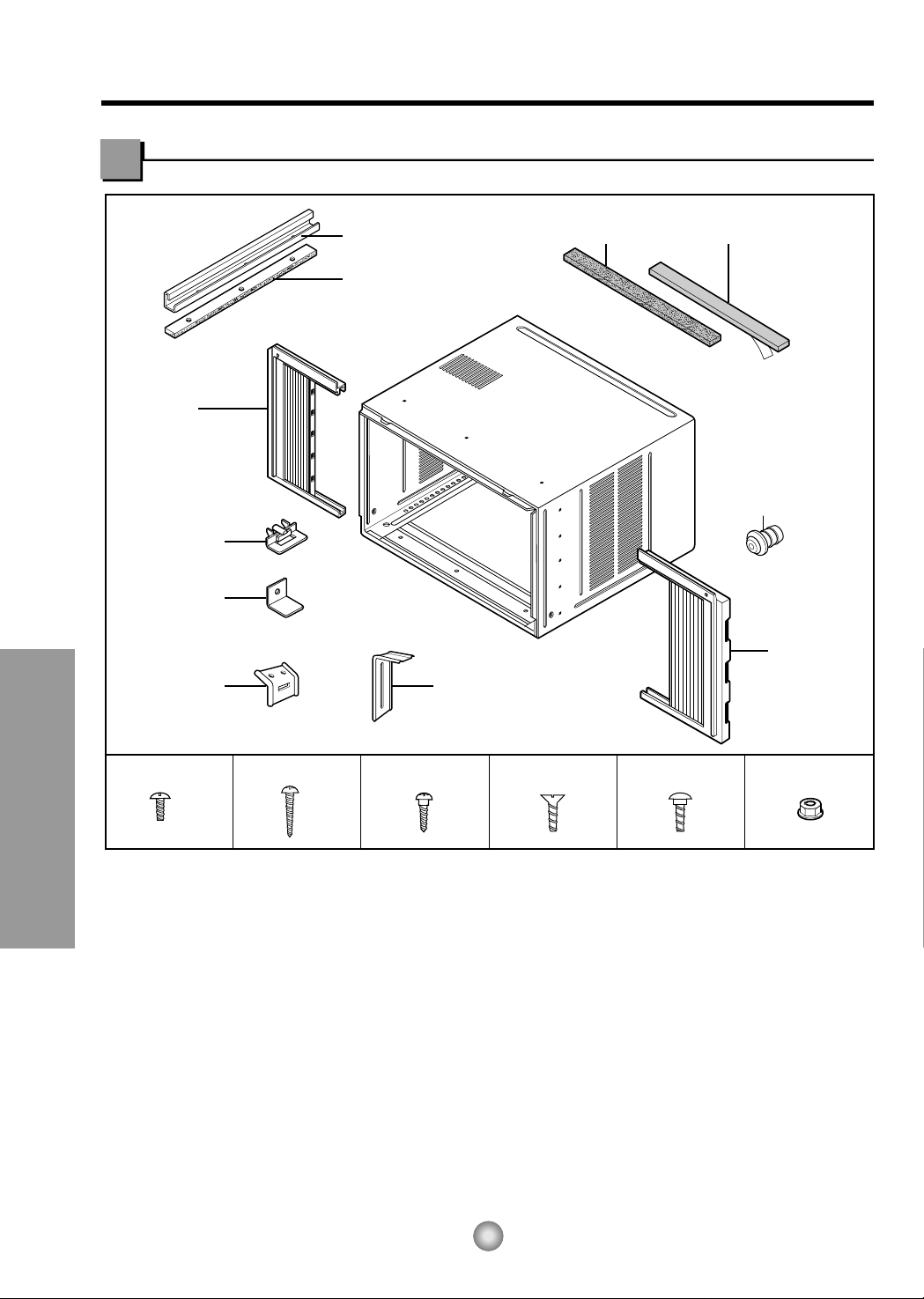
Foam-PE
(Adhesive-Backed)
Foam-PE
(Adhesive-Backed)
Type C (5) Type D (2)
Type A (14)
Carriage Bolt (2) Lock Nut (4)
Top retainer bar
Type B (7)
Foam strip
(Plain-Back)
Right frame
curtain
Drain pipe
Window locking
bracket
Left frame
curtain
Frame guide(2)
Sill
bracket
(2)
Support bracket(2)
10
Features and Installation
Installation Kits Contents
 Loading...