


CY-VHD9401U
Table of contents
 Loading...
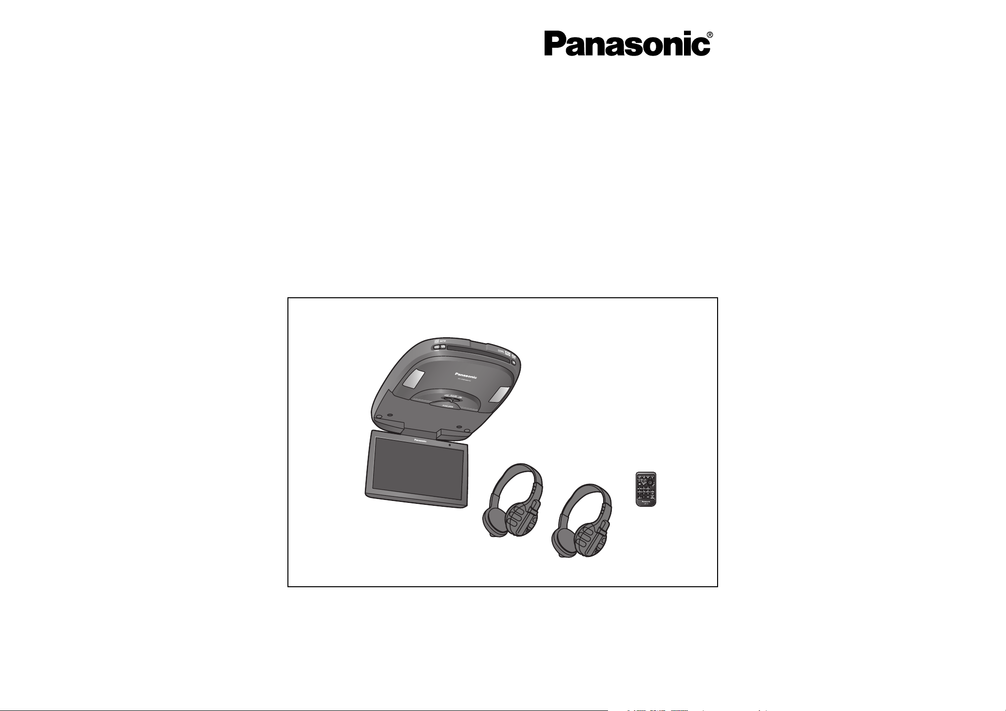
Installation Instructions
Instructions d’installation
Instrucciones de instalación
Overhead 9q Widescreen Color LCD Monitor with Built-in DVD Player
Moniteur plafond couleur à ÉCL de 9 po (grand-écran) avec lecteur DVD intégré
Monitor de pantalla ancha LCD de 9q a color con reproductor incorporado de DVD
para instalación en el techo del auto
CY-VHD9401U
CY-VHD9401L
≥ Please read these instructions carefully before using this product and keep this manual for future reference.
≥ Prière de lire ces instructions attentivement avant d’utiliser Ie produit et garder ce manuel pour l’utilisation ultérieure.
≥ Lea con atención estas instrucciones antes de utilizar el producto y guarde este manual para poderlo consultar en el futuro.
2
CY-VHD9401U/L
E
N
G
L
I
S
H
CY-VHD9401U/L
3
E
N
G
L
I
S
H
Safety Information
∫ Read the operating instructions for the unit and
all other components of your car audio system
carefully before using the system. They contain
instructions about how to use the system in a
safe and effective manner. Panasonic assumes
no responsibility for any problems resulting from
failure to observe the instructions given in this
manual.
Warning
This pictograph intends to alert
you to the presence of important
operating instructions and
installation instructions. Failure to
heed the instructions may result in
severe injury or death.
∫ This manual uses pictographs to show you how to
use the product safely and to alert you to potential
dangers resulting from improper connections
and operations. The meaning of the pictographs
are explained below. It is important that you fully
understand the meanings of the pictographs in
order to use this manual and the system properly.
Caution
This pictograph intends to alert
you to the presence of important
operating instructions and installation
instructions. Failure to heed the
instructions may result in injury or
material damage.
Observe the following warnings when
installing.
q Do not, under any circumstances, install the
product in a place where the driver’s ability to
drive the car or the driver’s fi eld of vision will
be impaired.
Installing the product in a place where it will
interfere with the driver’s fi eld of vision either
in front or behind or in a place where it will
interfere with the driver’s ability to drive the car
may lead to traffi c accidents and/or injury.
q Have a professional technician wire and install
the product.
Professional skill and experience is required
to wire and install the product. Improper
installation could result in failure of safety
equipment resulting in accident and injury.
For safety’s sake, always ask the store from
which you purchased the product to install and
wire it for you.
q Use in DC 12 V - grounded vehicles.
This
product
is only for DC 12 V - grounded
vehicles. It cannot be used in DC 24 V vehicles
(such as large trucks, diesel vehicles designed
for cold climates, etc.).
Using this
product
in such vehicles could cause
fi re or other malfunction.
Warning
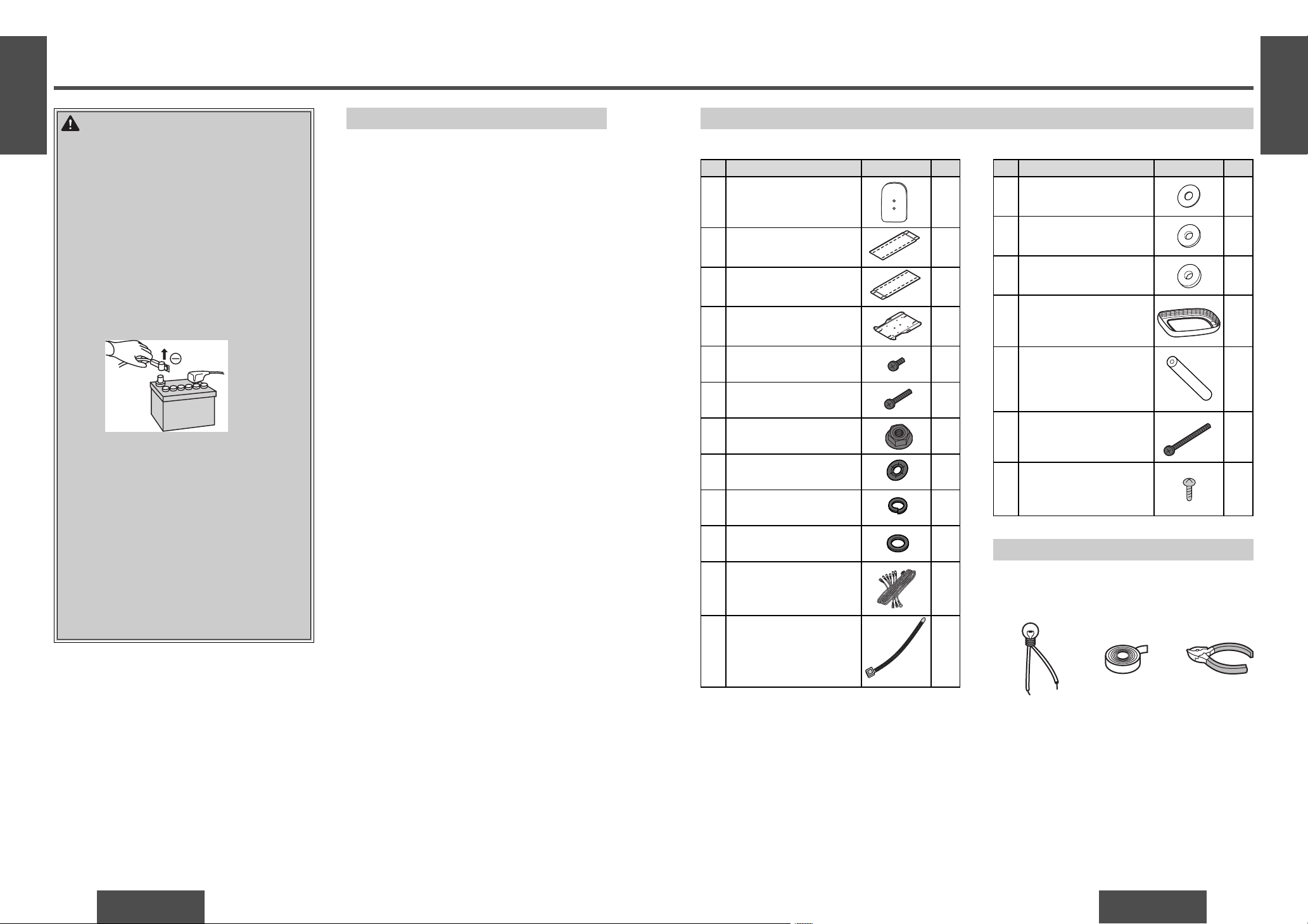
q Be sure to disconnect the battery’s - terminal
while wiring and installing the product.
Doing the wiring and installation with the
battery’s - terminal still connected could cause
electrical shock and injury due to a short circuit
accidents.
q Install the product securely so that it will not
shift out of place or drop down.
Loose screws or insecure installation may cause
the product to shift out of position or drop
down, etc. while the car is moving, resulting in
an accident and/or injury.
q Do not disassemble, repair or modify the
product.
Do not disassemble, repair or modify the
product, or cut the cord to connect it to the
power supply for another device. This could
cause fi re, electrical shock or other malfunction.
q Never use the car’s safety equipment for
installing or grounding the product.
Using the bolts, nuts and screws of the car’s
safety equipment (steering and brake systems,
fuel tank, etc.) could cause accidents. Follow
the instructions and only use the accessories
provided with the product and the specifi ed
parts.
q Install the product after checking the position
of the car’s pipes, tank and electrical wiring.
When opening holes in the car body to install
the
product
, be careful not to touch or interfere
with the pipes, tank or electrical wiring. Doing
so could cause fi re or accidents.
q Always use the accessories provided with the
product and the specifi ed parts.
Using parts other than those specifi ed could
damage the inside of the product or cause the
product to not be securely fastened and thus
come loose, which could cause accidents,
malfunction or fi re.
q Do not install the product in a location where
it will be subject to heavy vibration or in an
unstable location.
Installing the product in a sloping location or on
a noticeably curved surface, etc. may cause the
product to shift out of position or drop down,
etc. while the car is moving, resulting in an
accident and/or injury.
q Follow the instructions to install and wire the
product.
Failure to follow the instructions to properly
install and wire the product could cause
accidents or fi re.
q Run the cords so that they do not interfere with
driving or with entering or exiting the car.
Run the cords so that they do not wrap around
the steering wheel, gearshift, brake pedal, etc.
or around your legs, and secure all the cords
together. Failure to do so could cause accidents
or injury.
Observe the following warnings when
installing. (Continued)
q Do not install the product in a position where it
will interfere with the operation of the air bag.
The air bag may fail to operate properly or the
main unit or its parts could become dislodged
and end up fl ying through the air by an air bag
which has opened, causing an accident and/or
injury.
q Be sure to use fuses with the prescribed
capacity. Have a professional technician
replace the fuses.
Using fuses that exceed the prescribed capacity
could cause the
product
to start smoking, ignite
or otherwise malfunction. For replacement and
repair of fuses, contact the store from which you
purchased your
product
or a nearby Panasonic
Servicenter.
q Contact your car dealer or manufacturer
to determine the required procedure and
strictly follow their instructions before
attempting installation of this product if your
car is equipped with air bag and/or anti-theft
systems.
Specifi c procedures may be required for
connection and disconnection of the battery
to install this product. Failure to follow the
procedure may result in the unintended
deployment of air bags or activation of the
anti-theft system resulting in damage to the car
and personal injury.
Warning
NO WARRANTY
Panasonic shall have no liability for reduction in safety or any accident caused by installing this
product. We shall not guarantee any auto parts damaged during installation.
4
CY-VHD9401U/L
E
N
G
L
I
S
H
CY-VHD9401U/L
5
E
N
G
L
I
S
H
Safety Information
(continued)
Observe the following cautions when
using this unit or installing.
q If an RCA or similar cord is to be connected
to the product, adjust its position and length
so that it will not become entangled or come
into contact with your body. After use, be
absolutely sure to disconnect it from the
product.
Failure to heed this caution may result in an
accident and/or injury.
q Before connecting the product with another
device, consult the operating instructions
of the device concerned to ensure that the
product and device will be connected properly.
Incorrect connections may cause accidents
and/or malfunctioning.
Observe the following cautions when
replacing the bulb of the dome light.
≥ Have the dome light replaced by a qualifi ed
specialist.
≥ While you are replacing a bulb, be absolutely
sure to keep the dome light switch at OFF.
Otherwise, you may burn yourself.
≥ The bulb is very hot to touch while it is lighted
and immediately after it has gone off.
≥ Before attempting to replace it, turn the dome
light switch off, wait several minutes and then
check that it cooled off.
≥ Use a bulb with the specifi ed ratings (12 V/5 W).
Do not use any other bulb.
≥ Gripping the bulb with too much force may
break it. Wear fi ngerstalls or use some other
anti-slip method when replacing it.
Caution
Observe the following cautions when
installing.
q Do not damage the cords.
Wire breaks and short circuits can cause
electrical shock or fi re.
Run the cords so that they do not get tangled in
the moving parts (such as the seat rails), screws
or car body.
Do not damage, pull too hard, fold, twist, or
work on the cords. Do not place the cords near
heating appliances or put heavy objects on the
cords.
q Install the monitor in a position where it will
not hit anybody’s head when it opens and
closes.
Failure to heed this caution may result in an
accident and/or injury.
q Take care not to injure your fi ngers with the
power drill or other tool you are using. Also
take care not to damage the wiring near the
ceiling panel.
Failure to heed this caution may result in an
accident, injury and/or malfunctioning.
q Do not poke your fi ngers between the ceiling
and this product.
Failure to heed this caution may result in an
injury and/or malfunctioning of the product.
q Wear gloves for installation work to protect
yourself from injuries.
Failure to heed this caution may result in an
accident and/or injury.
q Take care that the wiring is not pinched or
caught by the base plate attached to the roof
or any other parts.
Failure to heed this caution may result in an
accident and/or injury.
q Before installing the unit, be absolutely sure to
check that the screws do not make any contact
with the ceiling panel.
If some space is required between the base plate
and the unit, attach and adjust the under cover.
For details on installing the under cover, consult
your dealer.
q Wear goggles or protective eyewear to shield
your eyes from airborne metal particles during
drilling.
Failure to heed this caution may result in an
accident and/or injury.
q As you cut the headliner, take care not to cut
your fi ngers. Also take care not to damage any
other areas of the headliner.
Failure to heed this caution may result in an
accident and/or injury.
q Follow local rules and regulations for
installing the unit.
Observe the following cautions for
connections.
≥ To prevent damage to the unit, be sure to follow
the connection diagram.
≥ Do not connect the power connector to the unit
until the wiring is completed.
≥ When connecting stripped wires, be sure to
wrap them securely with electrical tape to
prevent shorts.
≥ Bundle all cables and keep cable terminals free
from touching any metal parts.
Safety Information ........... Page 2
Before Installation ................ 14
Safety Installation Diagram ................ 14
Open the Display Unit......................... 15
Close the Display Unit ........................ 15
Display Unit Lateral Angle
Adjustment....................................... 15
Installation Guide................. 16
Overview ............................................ 16
Supplied Hardware............................. 17
Required Tools................................... 17
Identify All Leads................................ 18
Connect All Leads .............................. 19
Final Installation ................................. 19
Final Checks ....................................... 19
Installation..........................20
Introduction ....................................... 20
Work Flow.......................................... 21
Installation Procedures ...................... 22
Electrical Connections ........... 30
Wiring Diagram (Simple System)....... 30
Wiring Diagram
(Recommended System).................. 32
Wiring Diagram
(Advanced System).......................... 34
Note:
≥ For replacing the bulb of the dome light, please
refer to page 73 in the Operating Instructions.
Contents
F
R
A
N
Ç
A
I
S
6
CY-VHD9401U/L
F
R
A
N
Ç
A
I
S
CY-VHD9401U/L
7
Consignes de sécurité
∫ Veuillez d’abord lire le manuel d’instructions qui
accompagne cet appareil et ceux de tous les autres
composants de votre chaîne audio pour véhicule. Ils
contiennent des informations sur la façon d’utiliser
le système d’une manière sûre et effi cace. Panasonic
décline toute responsabilité quant à tout problème
résultant de l’ignorance des instructions fournies dans
ce manuel.
∫ Des pictogrammes sont utilisés dans ce manuel pour
vous indiquer comment utiliser l’appareil de manière
sûre et pour vous mettre en garde contre les dangers
pouvant résulter de connexions et d’opérations
inappropriées. La signifi cation des pictogrammes
respectifs est expliquée ci-dessous. Il est important
que vous compreniez pleinement le sens de ces
pictogrammes pour pouvoir utiliser ce manuel et la
chaîne de manière adéquate.
Mise en
garde
Ce pictogramme vous signale la
présence d’instructions d’utilisation et
d’instructions d’installation importantes.
Il y a risque de blessure grave ou de
décès si vous ignorez ces instructions.
Attention
Ce pictogramme vous signale la présence
d’instructions d’utilisation et d’instructions
d’installation importantes. Il y a risque de
blessure ou de dommage matériel si vous
ignorez ces instructions.
Mise en garde
Respectez les avertissements suivants
lors de l’installation.
o Vous ne devez dans aucune circonstance installer
l’appareil là où il nuira à la conduite du véhicule ou
obstruera le champ de vision du conducteur.
Il y a risque d’accident de la route et/ou de blessure
si l’appareil est installé là où il obstrue le champ de
vision du conducteur à l’avant ou à l’arrière, ou là ou
il nuit à la conduite du véhicule.
o Demandez à un technicien professionnel d’effectuer
le câblage et l’installation de l’appareil.
Le raccordement des câbles et l’installation de
l’appareil nécessitent les compétences et l’expérience
d’un professionnel. Une installation inadéquate peut
entraîner un dysfonctionnement des appareils de
sécurité pouvant causer un accident ou une blessure.
Par mesure de sécurité, demandez au personnel
du magasin où vous avez fait l’achat de l’appareil
d’installer ce dernier et de raccorder les câbles pour
vous.
o Utilisez l’appareil dans un véhicule équipé d’une
batterie 12 V cc avec prise de masse -.
Cet appareil est conçu exclusivement pour les
véhicules équipés d’une batterie 12 V cc avec prise de
masse -. Son utilisation n’est pas possible dans les
véhicules lourds équipés d’une batterie de 24 V cc (tels
que les camions lourds, les véhicules à moteur diesel
conçus pour les climats froids, etc.).
L’utilisation de cet appareil dans de tels véhicules
comporte un risque d’incendie ou de mauvais
fonctionnement.
o Assurez-vous d’avoir déconnecté la borne - de
la batterie avant de procéder au câblage et à
l’installation de l’appareil.
Si la borne - de la batterie est toujours
connectée au moment du câblage et de
l’installation, il a risque de choc électrique et de
blessure suite à un court-circuit.
o Installez le produit de façon sécuritaire, pour éviter
qu’il ne se déplace ou ne tombe.
Si les vis ne sont pas assez serrées ou si l’appareil
n’est pas solidement installé, ce dernier risque de se
déplacer ou de tomber pendant le déplacement du
véhicule, causant un accident et/ou une blessure.
o Ne pas démonter, réparer ou modifi er cet appareil.
Ne pas démonter, réparer ou modifi er cet appareil,
ni couper le cordon pour le connecter à la source
d’alimentation d’un autre appareil. Il y a risque
d’incendie, de choc électrique ou de mauvais
fonctionnement.
o N’utilisez en aucun cas les dispositifs de sécurité
du véhicule pour installer l’appareil ou le mettre à
la masse.
L’utilisation des boulons, écrous et vis des dispositifs
de sécurité du véhicule (direction et frein, réservoir
d’essence, etc.) risquerait de causer des accidents.
Suivez les instructions et utilisez exclusivement
les accessoires fournis avec
l’appareil
et les pièces
spécifi ées.
o Vérifi ez d’abord la position des tuyaux, réservoirs
et câbles électriques du véhicule avant d’installer
l’appareil.
Prenez garde de toucher les tuyaux, réservoirs et
câbles électriques si vous percez des trous pour
installer l’appareil. Cela risquerait de causer un
incendie ou un accident.
o Utilisez toujours les accessoires fournis avec
l’appareil et les pièces spécifi ées.
L’utilisation d’autres pièces que celles spécifi ées
comporte un risque d’endommagement des
composants internes ou elle peut causer une fi xation
non sécuritaire de l’appareil dont peuvent découler
des accidents, un mauvais fonctionnement ou un
incendie.
o N’installez pas l’appareil en un endroit où il sera
exposé à des vibrations intenses ou se trouvera en
position instable.
Si l’appareil est installé sur une surface inclinée, très
courbe, etc., il risque par exemple de se déplacer
ou de tomber pendant le déplacement du véhicule,
causant un accident et/ou une blessure.
o Suivez les instructions pour installer l’appareil et
raccorder les câbles.
Il y a risque d’accident ou d’incendie si l’installateur
ignore les instructions qui permettent d’installer
l’appareil et de raccorder les câbles correctement.
o Faites courir les cordons de façon à ce qu’ils ne
nuisent pas à la conduite du véhicule, ainsi qu’à la
montée et descente des passagers.
Faites courir les cordons de façon telle qu’ils ne
risquent pas de s’enrouler autour du volant, du levier
de changement de vitesse, de la pédale de frein, etc.,
ou encore autour de vos jambes. Attachez tous les
cordons ensemble. Sinon, il y a risque d’accident ou
de blessure.
Respectez les avertissements suivants
lors de l’installation. (suite)
o N’installez pas l’appareil en un point où il nuira
au déploiement éventuel d’un coussin de sécurité
gonfl able.
Il y a risque d’accident ou de blessure si le sac de
sécurité gonfl able ne fonctionne pas correctement
ou s’il projette l’appareil principal ou ses pièces en
s’activant.
o Vous devez utiliser des fusibles qui ont la capacité
exigée. Confi ez le remplacement des fusibles à un
technicien professionnel.
Si vous utilisez des fusibles dont la capacité est
supérieure à la capacité exigée,
l’appareil
risque
de dégager de la fumée, de prendre feu ou de mal
fonctionner. Pour le remplacement et la réparation
des fusibles, contactez le magasin où vous avez fait
l’achat de
l’appareil
ou le centre de service après-vente
Panasonic le plus près.
o Contactez votre concessionnaire ou le fabricant
pour qu’il vous indique la procédure requise, et
suivez rigoureusement les instructions reçues avant
de procéder à l’installation de cet appareil si votre
véhicule est équipé de coussins de sécurité
gonfl ables et/ou d’un système antivol.
Des procédures particulières peuvent être nécessaires
pour le raccordement et la déconnexion de la batterie
lors de l’installation de cet appareil. Le non-respect
de la procédure à suivre comporte un risque de
déploiement des coussins de sécurité gonfl ables ou
d’activation du système antivol par inadvertance, dont
peuvent résulter des dommages au véhicule ou des
blessures.
Mise en garde
SANS GARANTIE
Panasonic décline toute responsabilité quant à toute diminution du niveau de sécurité ou tout accident causé par
l’installation de cet appareil. Nous n’offrons aucune garantie quant à l’endommagement éventuel de pièces du
véhicule lors de l’installation.
F
R
A
N
Ç
A
I
S
8
CY-VHD9401U/L
F
R
A
N
Ç
A
I
S
CY-VHD9401U/L
9
Consignes de sécurité
(suite)
Attention
Respectez les mises en garde suivantes
lors de l’installation.
o N’endommagez pas les cordons.
Toute rupture de fi l ou court-circuit peut causer un
choc électrique ou un incendie.
Faites courir les cordons de façon telle qu’ils ne
s’enchevêtreront pas dans les pièces mobiles (tels que
les glissières de siège), les vis ou la carrosserie du
véhicule.
Ne pas endommager, tendre excessivement, plier,
torsader ou modifi er les cordons. Ne pas placer les
cordons près d’un appareil de chauffage ou sous un
objet lourd.
o Installez le moniteur dans une position où il ne
risque pas de frapper la tête d’un passager lorsqu’il
s’ouvre et se ferme.
Il y a risque d’accident et/ou de blessure si vous
ignorez cette mise en garde.
o Prenez garde de vous blesser aux doigts avec la
perceuse électrique ou tout autre outil utilisé.
Prenez garde également d’endommager le câblage
à proximité du panneau du plafond.
Il y a risque d’accident, de blessure et/ou de mauvais
fonctionnement si vous ignorez cette mise en garde.
o N’insérez pas les doigts entre le plafond et
l’appareil.
Il y a risque de blessure et/ou de dysfonctionnement
si vous ignorez cette mise en garde.
o Pour éviter les blessures, portez des gants lorsque
vous effectuerez les travaux d’installation.
Il y a risque d’accident et/ou de blessure si vous
ignorez cette mise en garde.
o Assurez-vous que le câblage n’est pas coincé ou
immobilisé par la plaque de base fi xée au toit ou à
toute autre pièce.
Il y a risque d’accident et/ou de blessure si vous
ignorez cette mise en garde.
o Avant d’installer l’appareil, vous devez vous
assurer que les vis n’entrent pas en contact avec le
panneau du plafond.
Si un dégagement est nécessaire entre la plaque
de base et l’appareil, fi xez le sous-couvercle et
ajustez-le. Pour plus de détails sur l’installation du
sous-couvercle, contactez votre détaillant.
o Portez des lunettes étanches ou des lunettes
de protection pour protéger vos yeux contre les
particules de métal projetées lors du perçage.
Il y a risque d’accident et/ou de blessure si vous
ignorez cette mise en garde.
o Prenez garde de vous couper les doigts en coupant
la garniture de toit. Prenez garde également
d’endommager toute autre partie de la garniture de
toit.
Il y a risque d’accident et/ou de blessure si vous
ignorez cette mise en garde.
o Respectez les règles et règlements locaux lors de
l’installation de l’appareil.
Respectez les mises en garde suivantes
lors du raccordement.
≥ Pour éviter d’endommager l’appareil, suivez
rigoureusement les indications du schéma de
raccordement.
≥ Ne raccordez pas le connecteur d’alimentation à
l’appareil avant que tous les raccordements ne soient
terminés.
≥ Pour raccorder des câbles dénudés, recouvrez-les de
ruban électrique pour éviter les courts-circuits.
≥ Regroupez tous les câbles et gardez-les à l’écart des
parties métalliques du véhicule.
Respectez les mises en garde suivantes
lorsque vous utilisez ou installez cet
appareil.
o Si vous devez raccorder un cordon RCA ou similaire
à l’appareil, placez-le et ajustez sa longueur de
façon telle qu’il ne risque pas de s’enchevêtrer ou
d’entrer en contact avec une partie de votre corps.
Une fois l’utilisation terminée, vous devez le retirer
de l’appareil.
Il y a risque d’accident et/ou de blessure si vous
ignorez cette mise en garde.
o Avant de raccorder l’appareil à un autre composant,
consultez le mode d’emploi de ce dernier pour être
sûr d’effectuer correctement le raccordement.
De mauvais raccordements peuvent causer un accident
et/ou un mauvais fonctionnement.
Respectez les mises en garde suivantes
lorsque vous remplacez l’ampoule du
plafonnier.
≥ Faites remplacer le plafonnier par un technicien
spécialisé.
≥ Vous devez laisser le plafonnier éteint lorsque vous
remplacez une ampoule. Autrement, vous risquez de
vous brûler.
≥ L’ampoule est extrêmement chaude lorsqu’elle est
allumée ou vient tout juste d’être éteinte.
≥ Avant d’essayer de la remplacer, éteignez le plafonnier,
attendez quelques minutes puis assurez-vous qu’elle
est refroidie.
≥ Utilisez une ampoule conforme aux spécifi cations
(12 V/5 W). N’utilisez aucun autre type d’ampoule.
≥ Vous risquez de casser l’ampoule si vous la serrez trop
fort. Pour la remplacer, portez des doigtiers ou utilisez
un matériau qui ne glisse pas.
Consignes de sécurité .......Page 6
Avant l’installation ................ 36
Schéma d’installation sécuritaire......... 36
Ouvrez l’unité d’affi chage .................... 37
Fermez l’unité d’affi chage.................... 37
Ajustement latéral de l’angle de l’unité
d’affi chage ......................................... 37
Guide d’installation ............... 38
Vue d’ensemble................................... 38
Matériel fourni..................................... 39
Outils requis........................................ 39
Identifi cation de tous les fi ls ................40
Raccordement de tous les fi ls ..............41
Installation fi nale .................................41
Dernières vérifi cations .........................41
Installation.......................... 42
Introduction ........................................ 42
Flux de travaux.....................................43
Procédures d’installation......................44
Raccordements électriques ...... 52
Schéma de câblage
(système simple)............................... 52
Schéma de câblage
(système recommandé) .................... 54
Schéma de câblage
(système évolué)............................... 56
Table des matières
Remarque :
≥ Pour remplacer l’ampoule du plafonnier,
veuillez vous reporter à la page 117 du Manuel
d’instructions.
E
S
P
A
Ñ
O
L
10
CY-VHD9401U/L
E
S
P
A
Ñ
O
L
CY-VHD9401U/L
11
Información para su seguridad
A la hora de la instalación
Advertencias
Observe las siguientes advertencias
cuando haga la instalación.
q Bajo ninguna circunstancia instale el producto en
un lugar en el que se entorpezca la capacidad del
conductor para manejar el vehículo o se reduzca su
campo de visión.
La instalación del producto en un lugar en el que
interfi era con el campo de visión delantero o trasero
del conductor o en un lugar en el que interfi era con
la capacidad del conductor de manejar el vehículo,
puede provocar accidentes de tráfi co y/o lesiones.
q Solicite la instalación y el cableado del producto
por parte de un profesional cualifi cado.
Se requiere experiencia y preparación profesionales
para cablear e instalar el producto. Una instalación
inadecuada podría ocasionar fallos en el equipo
de seguridad, lo que traería como consecuencia
accidentes y lesiones.
Por seguridad, solicite siempre la instalación y el
cableado del producto a la tienda donde lo compró.
q Utilícelo en vehículos conectados a tierra de 12 V
CC -.
Este producto sólo vale para vehículos de 12 V
CC - conectados a tierra. No se puede usar en
vehículos de y 24 V CC (como camiones grandes,
vehículos diésel diseñados para climas fríos, etc.).
El uso de este producto en tales vehículos podría
causar incendios y otros fallos.
q Asegúrese de desconectar el terminal - de la pila
mientras cablea e instala el producto.
La ejecución del cableado y la instalación con el
terminal - de la pila aún conectado podría acarrear
descargas eléctricas y lesiones debido a accidentes
causados por cortocircuitos.
q Instale el producto fi rmemente de manera que no
se mueva de su sitio ni se caiga.
Si hay tornillos sueltos o una instalación insegura, el
producto se puede mover de su sitio o caerse, etc.,
mientras el vehículo está en marcha, lo que puede
ocasionar accidentes y/o lesiones.
q No desensamble, repare ni modifi que el producto.
No desensamble, repare ni modifi que el producto,
ni corte el cable para conectarlo a un suministro
eléctrico destinado a otro dispositivo. De lo contrario
se podrían producir incendios, descargas eléctricas y
otros fallos.
q Nunca utilice el equipo de seguridad del vehículo
para instalar o conectar a tierra el producto.
El uso de los pernos, tuercas y tornillos del equipo
de seguridad del vehículo (sistemas de dirección
y de frenos, depósito de combustible, etc.) podría
ocasionar accidentes. Siga las instrucciones y use
sólo los accesorios suministrados con el
producto
y
las piezas especifi cadas.
q Instale el producto tras comprobar la posición de
los tubos del vehículo, del depósito, y del cableado
eléctrico.
Al hacer agujeros en la estructura del vehículo para
instalar el
producto
, tenga cuidado de no tocar o
interferir con los tubos, el depósito, o el cableado el
éctrico. De lo contrario podría ocasionar incendios o
accidentes.
q Use siempre los accesorios suministrados con el
producto y las piezas especifi cadas.
Si se usan piezas distintas a las especifi cadas, se
podría dañar el interior del producto, o impedir su
inmovilización segura, con lo cual podría soltarse y
ocasionar accidentes, fallos o incendios.
q No instale el producto en un lugar en el que esté
sometido a vibraciones fuertes o sea inestable.
Si se instala el producto en un lugar en pendiente o
sobre una superfi cie visiblemente curvada, etc., puede
ocurrir que el producto cambie de sitio o se caiga,
etc., mientras el vehículo está en marcha, lo que
podría ocasionar accidentes y/o lesiones.
q Siga las instrucciones para instalar y cablear el
producto.
Si no se siguen las instrucciones para instalar y
cablear correctamente el producto, se pueden producir
accidentes e incendios.
q Coloque los cables de manera que no interfi eran
con la conducción del vehículo o con la entrada y
salida del mismo.
Coloque los cables de manera que no se puedan
enredar con el volante, el cambio de marchas, el
pedal del freno, etc., o con sus piernas, y fi je todos
los cables juntos. De lo contrario podría ocasionar
accidentes y lesiones.
Observe las siguientes advertencias
cuando haga la instalación.
(Continuación)
q No instale el producto en una posición en la que
interfi era con el funcionamiento de alguna bolsa de
aire.
La bolsa de aire no funcionará como es debido
o la unidad principal o alguna de sus partes se
desprenderá y saldrán volando por el impacto de una
bolsa de aire accionada, causando accidentes y/o
lesiones.
q Asegúrese de usar fusibles con las especifi caciones
especifi cadas. Solicite los servicios de un
profesional cualifi cado para reemplazar los
fusibles.
Si se usan fusibles que excedan la capacidad
especifi cada, podría ocurrir que el producto empezara
a echar humo, se incendiara, o fallara de alguna otra
forma. Para efectuar el recambio o la reparación de
los fusibles, póngase en contacto con la tienda en
donde compró el producto o con algún centro de
servicio de Panasonic cercano.
q Póngase en contacto con su distribuidor o con
el fabricante para determinar el procedimiento
requerido, y siga rigurosamente sus instrucciones
antes de proceder a la instalación de este producto
en caso de que su vehículo esté equipado con
sistemas de bolsas de aire y/o de antirrobo.
Para instalar este producto, pueden ser necesarios
procedimientos específi cos para la conexión y
desconexión de la pila. Si se hace caso omiso
de tales procedimientos, se podría provocar el
despliegue indeliberado de las bolsas de aire o la
activación involuntaria del sistema antirrobo, lo
que podría acarrear daños al vehículo y lesiones
personales.
Advertencias
∫ Lea los manuales de instrucciones de la unidad y
de todos los demás componentes de su sistema de
audio de automóvil cuidadosamente antes de utilizar
el sistema. Dichos manuales contienen instrucciones
sobre cómo utilizar el sistema de manera segura y
efectiva. Panasonic no se responsabilizará de ningún
problema debido a la no observancia de las
instrucciones ofrecidas en este manual.
Advertencias
Esta pictografía tiene como intención
alertarle sobre la presencia de
instrucciones de operación e
instrucciones de instalación
importantes. El no observar estas
instrucciones podrá resultar en
lesiones graves o muerte.
∫ En este manual se utilizan pictografías para mostrarle
cómo utilizar el producto de forma segura y alertarle
sobre peligros potenciales debidos a conexiones y
operaciones incorrectas. A continuación se explican
los signifi cados de las pictografías. Es importante
que entienda completamente los signifi cados de las
pictografías para poder utilizar este manual y el sistema
debidamente.
Precauciones
Esta pictografía tiene como intención
alertarle sobre la presencia de
instrucciones de operación e
instrucciones de instalación
importantes. El no observar estas
instrucciones podrá resultar en
lesiones o daños materiales.
SIN GARANTÍAS
Panasonic no es responsable de la merma en la seguridad ni de ningún accidente debido a la instalación de este
producto. No garantizamos ninguna pieza del vehículo que resulte dañada durante la instalación.
E
S
P
A
Ñ
O
L
12
CY-VHD9401U/L
E
S
P
A
Ñ
O
L
CY-VHD9401U/L
13
Información para su seguridad
(Continuación)
Observe las siguientes precauciones
cuando haga la instalación.
q No dañe los cables.
Las rupturas en los cables y los cortocircuitos pueden
ocasionar descargas eléctricas o incendios.
Coloque los cables de manera que no se enreden
en las partes móviles (tales como los rieles de los
asientos), en los tornillos, o en la carrocería del
vehículo.
No dañe los cables, ni tire de ellos con demasiada
fuerza, ni los doble, ni los tuerza, ni ande con ellos.
No coloque los cables cerca de aparatos calentadores
ni ponga objetos pesados encima de los mismos.
q Instale el monitor en tal posición que no se golpee
la cabeza de nadie al abrir o al cerrar.
Si se hace caso omiso de esta precaución, se pueden
producir accidentes y/o lesiones.
q Tenga cuidado de no lesionarse los dedos con el
taladro eléctrico o con la herramienta que esté
usando. Tenga cuidado también de no dañar el
cableado situado junto al panel del techo.
Si se hace caso omiso de esta precaución, se pueden
producir accidentes, lesiones y/o averías.
q No meta los dedos entre el techo y este producto.
Si se hace caso omiso de esta precaución, se pueden
producir lesiones personales y/o averías en el
producto.
q Use guantes para efectuar la instalación con objeto
de protegerse contra una posible lesión.
Si se hace caso omiso de esta precaución, se pueden
producir accidentes y/o lesiones.
q Tenga cuidado de no pillar el cableado con la placa
base montada al techo o con cualquier otra pieza.
Si se hace caso omiso de esta precaución, se pueden
producir accidentes y/o lesiones.
Precauciones
q Antes de instalar la unidad, asegúrese de
comprobar que los tornillos no hacen ningún
contacto con el panel del techo.
Si hace falta algo de espacio entre la placa base y
la unidad, instale la cubierta inferior y ajústela. Para
obtener detalles sobre cómo instalar la cubierta
inferior, consulte a su distribuidor.
q Use gafas de seguridad o protectores oculares para
protegerse los ojos de las partículas de metal que
salgan despedidas durante el taladrado.
Si se hace caso omiso de esta precaución, se pueden
producir accidentes y/o lesiones.
q Al cortar la cabecera, tenga cuidado de no cortarse
los dedos. Tenga cuidado también de no dañar
ninguna otra parte de la cabecera.
Si se hace caso omiso de esta precaución, se pueden
producir accidentes y/o lesiones.
q Siga las normas y reglamentos locales para instalar
la unidad.
Observe las precauciones siguientes al
hacer las conexiones.
≥ Para prevenir daños a la unidad, asegúrese de seguir
el diagrama de conexiones.
≥ No conecte el conector de alimentación a la unidad
hasta que no se haya llevado a cabo la conexión de
todos los demás cables.
≥ Al conectar cables pelados, asegúrese de recubrirlos
bien con cinta aislante para prevenir cortocircuitos.
≥ Recoja todos los cables y mantenga todos sus
terminales fuera de contacto con cualquier pieza
metálica.
Observe las siguientes precauciones
cuando utilice esta unidad o la instale.
q Si se trata de conectar un cable RCA o similar al
producto, ajuste su posición y largura con objeto
de que no se enrede ni entre en contacto con
usted. Después de la utilización, asegúrese de
desconectarla del producto.
Si se hace caso omiso de esta precaución, se pueden
producir accidentes y/o lesiones.
q Antes de conectar el producto con otro dispositivo,
consulte el manual de instrucciones del dispositivo
para asegurarse de que dicha conexión es apropiada.
Las conexiones mal hechas pueden dar lugar a
accidentes y/o a fallos de funcionamiento.
Observe las siguientes precauciones
cuando sustituya la bombilla de la luz de
techo.
≥ Solicite el recambio de la luz del techo por parte de un
técnico cualifi cado.
≥ Al cambiar una bombilla, asegúrese bien de mantener
apagada la luz del techo. De lo contrario, podría
quemarse.
≥ La bombilla está muy caliente al tacto mientras está
encendida y poco después de apagarse.
≥ Antes de intentar cambiarla, apague la luz del techo,
espere unos minutos, y compruebe que se ha enfriado.
≥ Utilice una bombilla que se ajuste a las especifi caciones
indicadas (12 V/5 W). No use ninguna otra bombilla.
≥ Si se agarra la bombilla con demasiada fuerza, se puede
romper. Use dediles o algún otro método antideslizante
a la hora de cambiar la bombilla.
Índice
Información para su
seguridad ............... Página 10
Antes de la instalación............ 58
Diagrama de instalación segura .......... 58
Apertura de la unidad de pantalla........ 59
Cierre de la unidad de pantalla ............ 59
Ajuste del ángulo lateral de la
unidad de pantalla.............................. 59
Guía de instalación................ 60
Perspectiva general............................. 60
Hardware suministrado....................... 61
Herramientas necesarias..................... 61
Identifi cación de todos los cables ....... 62
Conexión de todos los cables.............. 63
Instalación defi nitiva .......................... 63
Últimas comprobaciones .................... 63
Instalación .......................... 64
Introducción........................................ 64
Flujo operativo .................................... 65
Procedimiento de instalación .............. 66
Conexiones eléctricas............. 74
Diagrama del cableado
(sistema sencillo).............................. 74
Diagrama del cableado
(sistema recomendado) .................... 76
Diagrama del cableado
(sistema avanzado) ........................... 78
Nota:
≥ Para cambiar la bombilla de la luz del techo, consulte
la página 161 del manual de instrucciones.
14
CY-VHD9401U/L
CY-VHD9401U/L
15
Before Installation
E
N
G
L
I
S
H
1
E
N
G
L
I
S
H
2
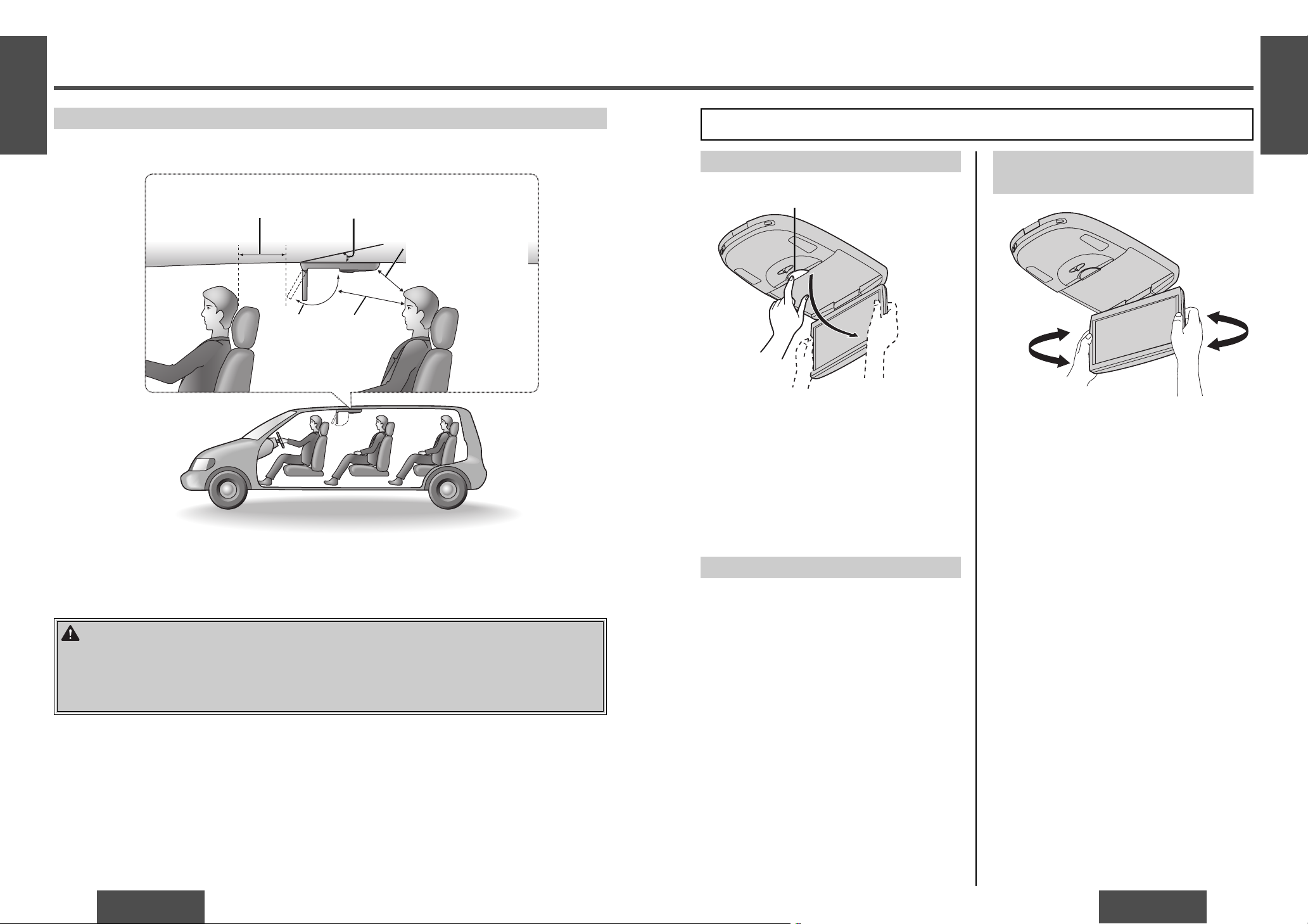
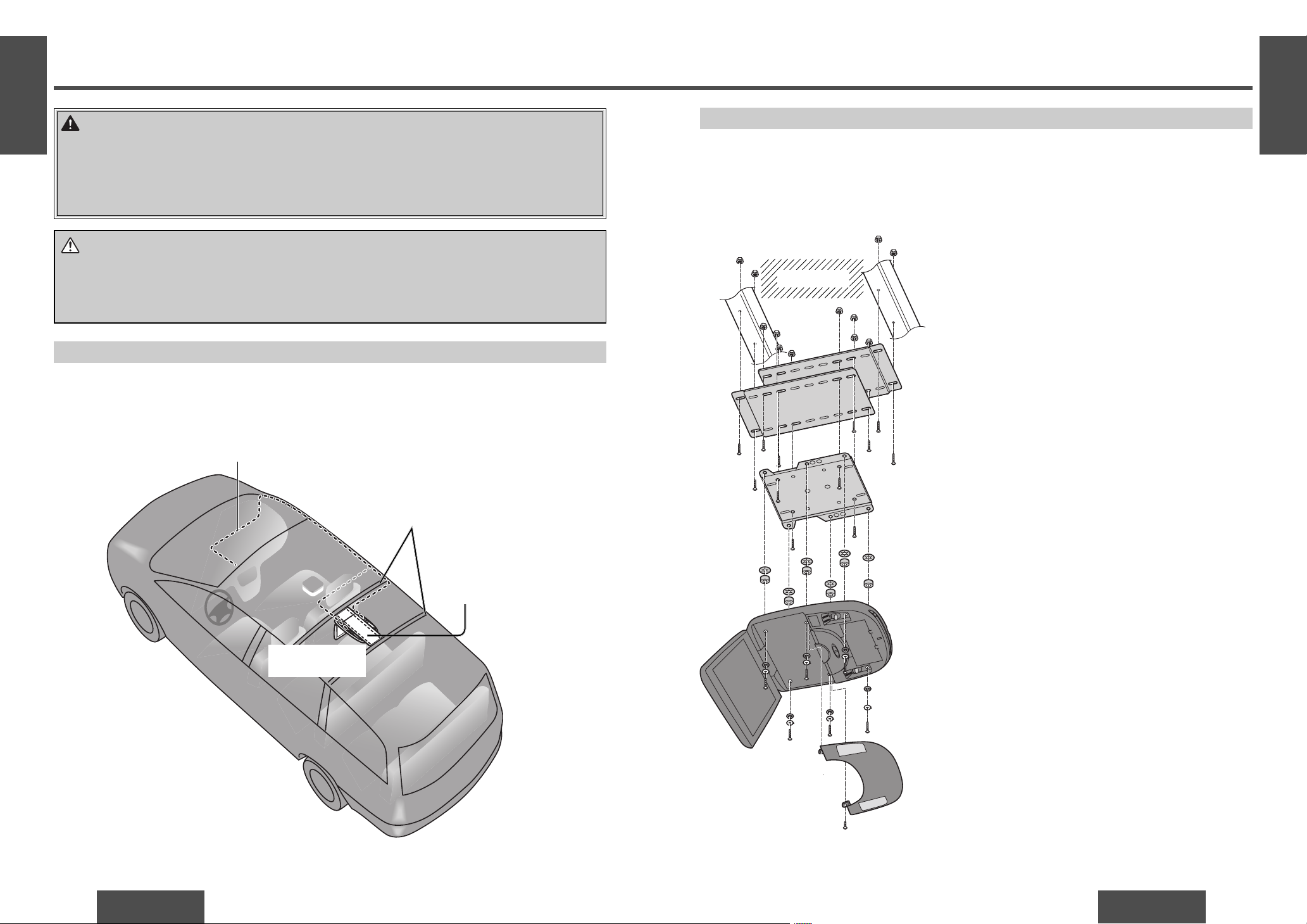
Display Unit Lateral Angle Adjustment
You can swivel it to the left and right, 30e each way.
Hold the display unit by the non-slip part in the
upper half of it and adjust its lateral angle.
Open the Display Unit
1 Push the display release button [PUSH OPEN]
until the display is unlocked.
(Press the button with one hand while holding
the display with the other.)
2 Open the display unit by both hands until a
comfortable viewing angle is reached.
Close the Display Unit
Move the display unit by both hands until the
display release button is locked.
Note:
≥ Always use both hands to open or close the
display unit.
≥ Always check that the display release button is
locked after closing the display unit.
≥ If the display unit cannot be locked, be sure to
consult your dealer and remedy the situation.
[PUSH OPEN]
Safety Installation Diagram
WARNING:
Have a professional technician wire and install the product.
Professional skill and experience is required to wire and install the product. Improper installation could
result in failure of safety equipment resulting in accident and injury. For safety’s sake, always ask the
store from which you purchased the product to install and wire it for you.
Approximately 150 mm {515/16q}*
Approximately
300 mm
{1113/16q }
Maximum
120˚
Approximately 300 mm
{1113/16q }
≥ This unit opens and closes at the maximum dimensions given below.
* Install the product in such a way as to maintain
the distances shown even when the display unit
is rotated by 30˚ toward the front seat headrest
(page 15).
Installation angle: Less than 20˚
Perform the adjustment below in order to provide the installation range shown in the fi gure on the left.
Maximum
120x
30x
30x
16
CY-VHD9401U/L
CY-VHD9401U/L
17
No. Item Diagram Q’ty
=
Space washer (A)
[t=1 mm {1/25q}]
6
>
Space washer (B)
[t=2 mm {2/25q}]
6
?
Space washer (C)
[t=3 mm {3/25q}]
6
@
Under cover 1
A
Space washer (D)
[t=80 mm {33/16q}]
6
B
Screw [No. 10-32 UNF,
L=100 mm {4q}]
6
C
Screw (for resin)
[2.6 mm {1/10q} ‡k
8 mm {8/25q}]
6
Installation Guide
E
N
G
L
I
S
H
3
E
N
G
L
I
S
H
4
Overview
Your fi rst step is to decide where to install it. The
instructions in these pages will guide you through
the remaining steps:
(Please refer to the “WARNING” statement.)
≥ Identify and label the car wires.
≥ Connect the car wires to the wires of the power
connector.
≥ Install the unit.
≥ Check the operation of the unit.
If you encounter problems, please consult your
nearest professional installer.
Before you begin installation, look for the items
which are packed with your unit.
≥ Warranty Card... Fill this out promptly.
≥ Panasonic Servicenter List for Service
Directory... Keep for future reference in case the
product needs servicing.
≥ Installation Hardware... Needed for installation.
WARNING:
≥ Use in DC 12 V - ground vehicles. This
product is only for DC 12 V - grounded
vehicles. It cannot be used in DC 24 V
vehicles (such as large trucks, diesel
vehicles designed for cold climates, etc.).
Using this product in such vehicles could
cause fi re or other malfunction.
≥ Be sure to disconnect the battery’s
- terminal while wiring and installing the
product. Doing the wiring and installation
with the battery’s - terminal still connected
could cause electrical shock and injury due
to a short circuit accidents.
≥ Contact your car dealer or manufacturer
to determine the required procedure
and strictly follow their instructions
before attempting installation of this
product if your car is equipped with
air bag and/or anti-theft systems.
Specifi c procedures may be required for
connection and disconnection of the battery
to install this product. Failure to follow the
procedure may result in the unintended
deployment of air bags or activation of the
anti-theft system resulting in damage to the
car and personal injury.
Note:
≥ Various settings that have been stored in the
memory in other on-board equipment (car
navigation etc.) may be lost if the battery
terminals are disconnected.
Therefore, we recommend to make a record of or
to back up the settings before disconnecting the
terminals.
After completing installation of the main unit, set
the equipment again according to the record.
12 V DC
Test bulb
Electrical tape Side-cut
pliers
Required Tools
You’ll need a screwdriver, and the following:
≥ Tools, cutter knife, cloth pieces are required for
the instructions.
≥ Use the tools of proper size to secure the bolts,
nuts and screws certainly.
Supplied Hardware
No. Item Diagram Q’ty
1
Paper template 1
2
Slide plate (upper)* 1
3
Slide plate (lower)* 1
4
Base plate 1
5
Screw [No. 10-32 UNF,
L=10 mm {3/8q}]
12
6
Screw [No. 10-32 UNF,
L=32 mm {11/4q}]
6
7
Nuts
(No. 10-32 UNF)
12
8
Push nuts
(No. 10-32 UNF)
6
9
Spring washer
[No. 10 (5 mm‡)]
6
:
Flat washer
[No. 10 (5 mm‡)]
6
;
Power connector 1
<
Cord clamp 2
ª For Installation
* The upper slide plate and lower slide plate can
be distinguished as follows: only the upper
slide plate has line “A” and “B” stamped on it
(page 23).
18
CY-VHD9401U/L
CY-VHD9401U/L
19
Installation Guide (continued)
E
N
G
L
I
S
H
5
E
N
G
L
I
S
H
6
The fi rst step in installation is to identify all the car
wires you’ll use when hooking up your LCD monitor.
As you identify each wire, we suggest that you label it
using masking tape and a permanent marker. This will
help avoid confusion when making connections later.
Identify All Leads Connect All Leads
Now that you have identifi ed all the wires in the car,
you are ready to begin connecting them to the LCD
monitor wires. The wiring diagram (page 30) shows
the proper connections and color coding of the
leads.
We strongly recommend that you test the unit
before making a fi nal installation.
You can set the unit on the fl oor and make
temporary connections to test the unit. Use
electrical tape to cover all exposed wires.
IMPORTANT:
≥ Connect the red power lead last, after
you have made and insulated all other
connections.
Power lead
Connect the red power lead to the correct car radio
wire or to the appropriate fuse port on the fuse
block. If the LCD monitor functions properly with all
these connections made, disconnect the wires and
proceed to the fi nal installation.
Battery lead
Connect the yellow battery lead to the correct radio
wire or to the battery fuse port on the fuse block.
Ground lead
Connect the black ground lead of the power
connector to the metal car chassis.
Equipment
Connect any optional equipment according to the
instructions furnished with the equipment. Read
the operating and installation instructions of any
equipment you will connect to this unit.
Final Installation
Lead Connections
Connect all wires, making sure that each connection
is insulated and secure. Bundle all loose wires and
fasten them with tape so they will not fall down
later.
Congratulations! After making a few fi nal checks,
you’re ready to enjoy your new LCD monitor.
Final Checks
1. Make sure that all wires are properly connected
and insulated.
2. Turn on the ignition to check the unit for proper
operation.
If you have diffi culties, consult your nearest
authorized professional installer for assistance.
Caution:
≥ Do not connect the power connector to the
unit until the wiring is completed. If there are
no plastic caps on the stereo hooking wires,
insulate all exposed leads with electrical
tape until you are ready to use them. Identify
the leads in the following order.
Power Lead
If your car has a radio or is
pre-wired for one:
Cut the connector wires
one at a time from the plug
(leaving the leads as long
as possible) so that you can
work with individual leads.
Turn the ignition on to the accessory position, and
ground one lead of the test bulb to the chassis.
Touch the other lead of the test bulb to each of the
exposed wires from the cut radio connector plug.
Touch one wire at a time until you fi nd the outlet
that causes the test bulb to light.
Now turn the ignition off and then on. If the bulb also
turns off and on, that outlet is the car power lead.
If your car is not wired for an audio unit:
Go to the fuse block and fi nd the fuse port for radio
(RADIO), accessory (ACC), or ignition (IGN).
Battery Lead
If the unit has a yellow lead, you will need to locate
the car’s battery lead. Otherwise you may ignore
this procedure. (The yellow battery lead provides
continuous power to maintain a clock, memory
storage, or other function.)
If your car has a radio or is pre-wired for one:
With the ignition and headlights off, identify the car
battery lead by grounding one lead of the test bulb
to the chassis and checking the remaining exposed
wires from the cut radio connector plug.
If your car is not wired for an audio unit:
Go to the fuse block and fi nd the fuse port for the
battery, usually marked BAT.
Dome light lead
The dome light lead connection varies depending on
the type of vehicle. Consult your dealer or service
technician.
Note for connecting the dome lights
(page 30s31):
≥ There are two common types of dome light
circuits used, positive or negative switched.
Positive systems supply voltage to the interior
lights to turn them on, negative switched
systems apply ground to illuminate the bulbs.
≥ The dome light lead connection varies
depending on the type of vehicle. Consult your
dealer or service technician.
≥ Both positive and negative switched light
circuits are supported by this unit’s door
switch. If the door switch is not wired correctly,
the dome light will not come on properly.
The polarity differs from one model to another
so be absolutely sure to ask a dealer or service
technician to wire and install the unit.
20
CY-VHD9401U/L
CY-VHD9401U/L
21
Installation
WARNING:
Have a professional technician wire and install the product.
Professional skill and experience is required to wire and install the product. Improper installation could
result in failure of safety equipment resulting in accident and injury.
For safety’s sake, always ask the store from which you purchased the product to install and wire it for
you.
E
N
G
L
I
S
H
7
Introduction
Note:
≥ The fi gure below shows installation in a simplifi ed
way. Do not rely on this fi gure alone as the basis
for installation. Instead, be sure to follow the
procedure on the following pages.
2
Attach the upper and lower
slide plates and base plate
to the ceiling reinforcement
crosspieces (page 22, 23).
3
Wire the unit and replace the
headliner (page 24, 25).
5
Connect the wires and attach
the main unit (page 28, 29).
4
Get ready to attach the main
unit (page 26, 27).
E
N
G
L
I
S
H
8
There are fi ve main steps to install the main unit.
For each step, follow the detailed procedures on
page 22`29.
Ceiling
reinforcement
crosspieces
Front cover
CY-VHD9401U/
CY-VHD9401L
Ceiling panel
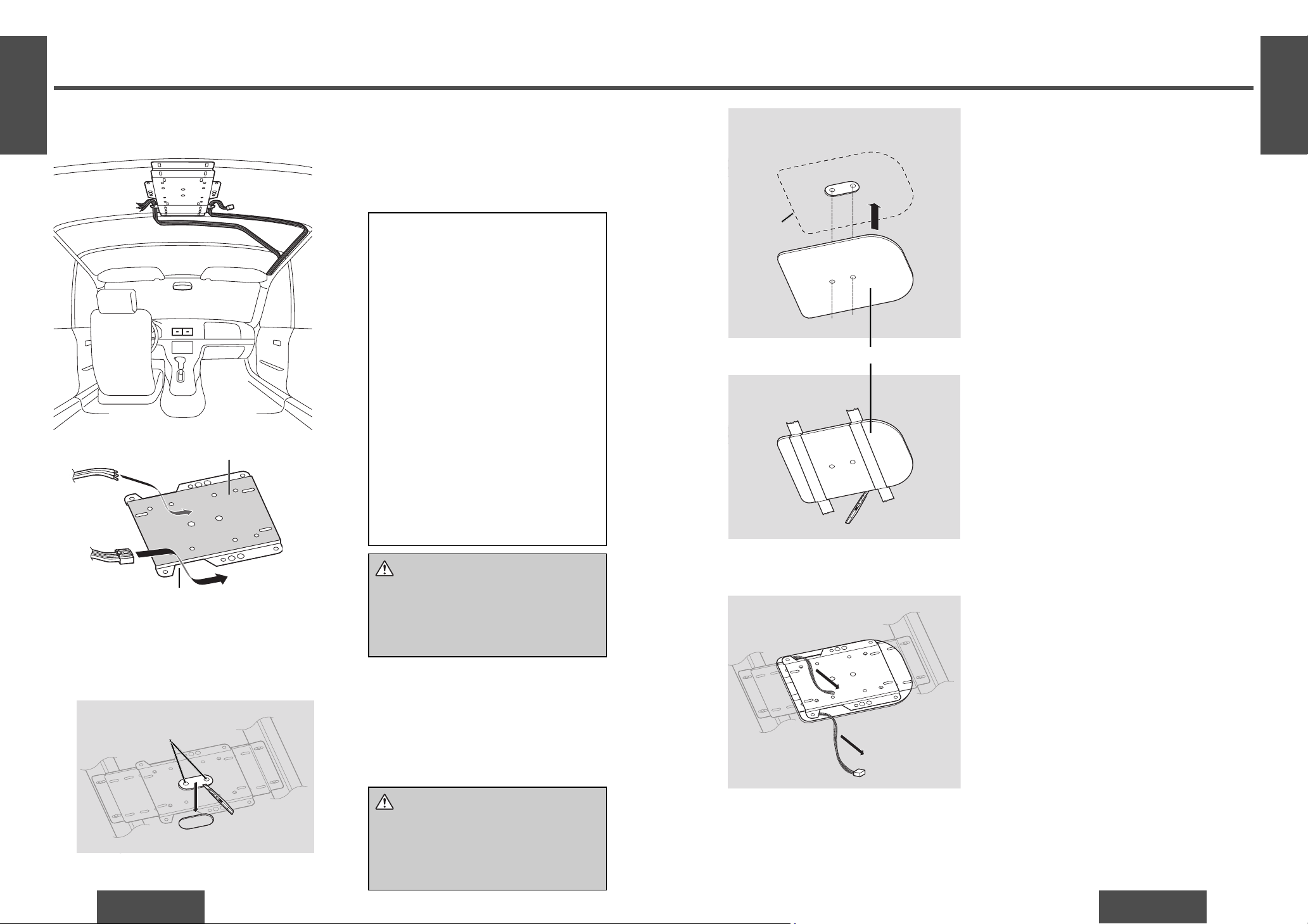
1
Remove the headliner from
the vehicle for installation
(page 22).
A sample installation is shown below for your reference.
First remove the headliner. Next, fi rmly attach the included upper and lower slide plates and base plate to the
two ceiling reinforcement crosspieces. Finally replace the headliner as it was and attach the main unit.
Work Flow
Slide plate (upper),
slide plate (lower),
base plate
CY-VHD9401U/
CY-VHD9401L
Ceiling reinforcement
crosspieces
Wiring
Caution:
≥ Wear gloves for installation work to protect yourself from injuries. Failure to heed this caution may
result in an accident and/or injury.
≥ Wear goggles or protective eyewear to shield your eyes from airborne metal particles during drilling.
Failure to heed this caution may result in an accident and/or injury.

22
CY-VHD9401U/L
CY-VHD9401U/L
23
Installation (continued)
E
N
G
L
I
S
H
9
E
N
G
L
I
S
H
10
Installation Procedures
Remove the headliner from the vehicle for installation.
1 Remove the interior headliner from the car in which the unit is to be installed while taking care not
to damage the interior or its fi ttings.
2 Now remove the dome light but leave its wiring in place.
5
Use the tool such as a power drill to drill holes
in the ceiling reinforcement crosspieces to meet
the mounting holes on the assembled plates.
Caution:
≥ Before drilling the holes, check exactly
where the unit and bracket are to be
installed. Take care not to injure your
fi ngers with the power drill or other tool
you are using. Also take care not to
damage the ceiling panel.
≥ Wear goggles or protective eyewear to
shield your eyes from airborne metal
particles during drilling. Failure to heed
this caution may result in an accident
and/or injury.
6
Affi x the assembled plates to the ceiling
reinforcement crosspieces securely using the
screws and nuts.
5
2
Attach the upper and lower slide plates and base plate to the ceiling
reinforcement crosspieces.
7 Nut
(No. 10-32 UNF)a 4
1 Carefully check the position of the ceiling
reinforcement crosspieces and determine where
the main unit will be installed.
Ceiling reinforcement
crosspieces
3 Slide
plate
(lower)
1
Note:
≥ Headliner construction and the position of chassis lights vary depending on the type of
vehicle. Do a preliminary check before starting work.
3 Decide the position for attaching the base plate
on the upper and lower slide plates. Attach it by
screwing in the included screws (5) and nuts
(7) in 8 positions.
2 Align the upper and lower slide plates with the
ceiling reinforcement crosspieces, sliding the
slide plates as you position them.
Note:
≥ Depending on the position of the lower slide
plate within the range of A or B shown in
the fi gure at left, screw the upper and lower
slide plates and base plate according to the
procedure below.
2 Slide
plate
(upper)
Edge of the
lower slide plate
Line ALine B
B Use all 8 screws to attach the 3 plates.
A Use 4 screws on the outside to attach the
upper and lower plates alone, and use
4 screws on the inside to attach all
3 plates.
4
Use an indelible marker to mark 4 positions on
the ceiling reinforcement crosspieces where you
will drill holes to attach the assembled plates.
Ceiling reinforcement
crosspieces
Assembled plates
5 Screw
[No. 10-32 UNF,
L=10 mm {3/8q}] a 8
7 Nut
(No. 10-32 UNF) a 8
7 Nut (No. 10-32 UNF)a 8
5 Screw
[No. 10-32 UNF, L=10
mm {3/8q}]a 8
5 Screw
[No. 10-32 UNF, L=10 mm {3/8q}]a 4
Tool such as a power drill
24
CY-VHD9401U/L
CY-VHD9401U/L
25
Installation (continued)
E
N
G
L
I
S
H
11
E
N
G
L
I
S
H
12
2 Put the headliner that was removed earlier back
in its original place.
3 In the re-attached headliner, locate the center
position of the base plate which has been
attached to the reinforcement crosspieces,
and cut out the section that will expose the
reference holes to view.
4 Align the guide holes in the accessory paper
template (1) with the reference holes which
can be seen from the section that was cut
out from the headliner, and paste the paper
template onto the headliner using a tape or
other thing.
Caution:
≥ As you cut the headliner, take care not
to cut your fi ngers. Also take care not to
damage any other areas of the headliner.
Failure to heed this caution may result in
an accident and/or injury.
Note:
≥ Some cars have a thick headliner, use
spacers or have other conditions that
prevent the use of blue ceiling refl ected
illumination. Before proceeding with the
installation, contact your dealer and fi nd
out whether your car allows the use of
refl ected light.
≥ Before cutting the headliner, check the
direction of the paper template to prevent
any mistakes in the installation position.
Headliner
Reference holes
1 Paper template
Cut out
Front side
Rear side
5 Pull out the wires that you pulled from the
pullout opening of the base plate beforehand so
that it will be easier to wire.
3
Wire the unit and replace the headliner.
1 Connect the wiring of the dome light and
the unit, and bring the wiring as far as the
installation position.
Caution:
≥ Pass the wiring you have brought to the
installation position through the pullout
openings in the base plate. Take care
that the wiring is not pinched or caught
by the top of the base plate.
Pullout openings
Base plate top
Note for connecting the dome lights
(page 30s31):
≥ There are two common types of dome
light circuits used, positive or negative
switched.
Positive systems supply voltage to the
interior lights to turn them on, negative
switched systems apply ground to
illuminate the bulbs.
≥ The dome light lead connection varies
depending on the type of vehicle. Consult
a service technician as needed.
≥ Both positive and negative switched
light circuits are supported by this
unit’s door switch. If the door switch
is not wired correctly, the dome
light will not come on properly.
The polarity differs from one model to
another so be absolutely sure to ask a
dealer or service technician to wire and
install the unit.
Loading...