


MOTOROLA SN74LS174ML2, SN74LS174MR1, SN74LS174N, SN74LS174D, SN74LS174DR2 Datasheet
...SN74LS174
Hex D Flip-Flop
The LSTTL / MSI SN74LS174 is a high speed Hex D Flip-Flop. The device is used primarily as a 6-bit edge-triggered storage register. The information on the D inputs is transferred to storage during the LOW to HIGH clock transition. The device has a Master Reset to simultaneously clear all flip-flops. The LS174 is fabricated with the Schottky barrier diode process for high speed and is completely compatible with all ON Semiconductor TTL families.
•Edge-Triggered D-Type Inputs
•Buffered-Positive Edge-Triggered Clock
•Asynchronous Common Reset
•Input Clamp Diodes Limit High Speed Termination Effects
GUARANTEED OPERATING RANGES
Symbol |
Parameter |
Min |
Typ |
Max |
Unit |
|
|
|
|
|
|
VCC |
Supply Voltage |
4.75 |
5.0 |
5.25 |
V |
TA |
Operating Ambient |
0 |
25 |
70 |
°C |
|
Temperature Range |
|
|
|
|
|
|
|
|
|
|
IOH |
Output Current ± High |
|
|
± 0.4 |
mA |
IOL |
Output Current ± Low |
|
|
8.0 |
mA |
http://onsemi.com
LOW
POWER
SCHOTTKY
16
1
PLASTIC
N SUFFIX
CASE 648
16
1
SOIC
D SUFFIX
CASE 751B
ORDERING INFORMATION
Device |
Package |
Shipping |
|
|
|
SN74LS174N |
16 Pin DIP |
2000 Units/Box |
|
|
|
SN74LS174D |
16 Pin |
2500/Tape & Reel |
|
|
|
Semiconductor Components Industries, LLC, 1999 |
1 |
Publication Order Number: |
December, 1999 ± Rev. 6 |
|
SN74LS174/D |

SN74LS174
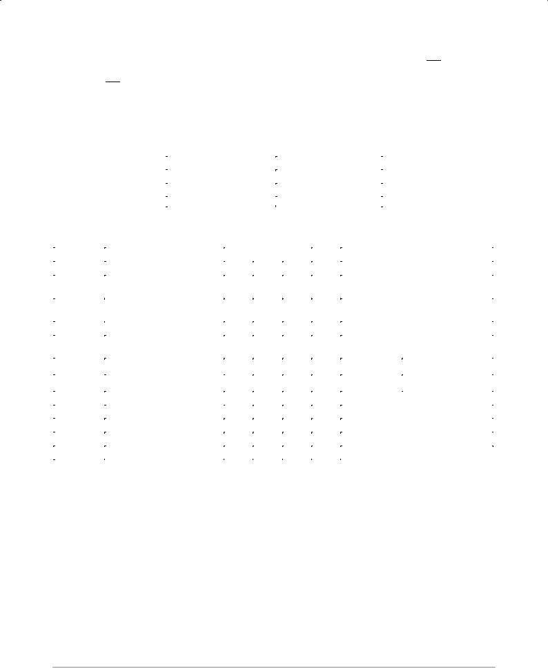
CONNECTION DIAGRAM DIP (TOP VIEW)
|
|
VCC |
|
Q5 |
D5 |
|
D4 |
|
|
|
|
Q4 |
D3 |
|
Q3 |
|
CP |
|
|
|
|||||
|
16 |
|
15 |
|
14 |
|
13 |
|
|
12 |
|
11 |
|
|
10 |
|
9 |
|
|
|
|
||||
|
|
|
|
|
|
|
|
|
|
|
|
|
|
|
|
|
|
|
|
|
|
|
|
NOTE: |
|
|
|
|
|
|
|
|
|
|
|
|
|
|
|
|
|
|
|
|
|
|
|
|
|
The Flatpak version has the same |
|
|
|
|
|
|
|
|
|
|
|
|
|
|
|
|
|
|
|
|
|
|
|
|
|
pinouts (Connection Diagram) as |
|
|
|
|
|
|
|
|
|
|
|
|
|
|
|
|
|
|
|
|
|
|
|
|
|
the Dual In-Line Package. |
|
|
|
|
|
|
|
|
|
|
|
|
|
|
|
|
|
|
|
|
|
|
|
|
|
|
|
|
1 |
|
2 |
|
3 |
|
4 |
|
|
5 |
|
6 |
|
|
7 |
|
8 |
|
|
|
|
||||
|
|
|
|
|
Q0 |
D0 |
|
D1 |
|
|
|
|
Q1 |
D2 |
|
Q2 |
|
GND |
|
|
|
||||
|
|
MR |
|
|
|
|
|
|
|
|
|
|
|
||||||||||||
|
|
|
|
|
|
|
|
|
|
|
|
|
|
|
|
|
|
|
LOADING (Note a) |
|
|||||
PIN NAMES |
|
|
|
|
|
|
|
|
|
|
|
|
|
|
|
HIGH |
|
LOW |
|
||||||
D0 ± D5 |
Data Inputs |
|
|
|
|
|
|
|
|
|
|
|
|
0.5 U.L. |
|
0.25 U.L. |
|||||||||
CP |
Clock (Active HIGH Going Edge) Input |
|
0.5 U.L. |
|
0.25 U.L. |
||||||||||||||||||||
|
|
|
|
Master Reset (Active LOW) Input |
|
|
|
0.5 U.L. |
|
0.25 U.L. |
|||||||||||||||
MR |
|
|
|||||||||||||||||||||||
Q0 ± Q5 |
Outputs |
|
|
|
|
|
|
|
|
|
|
|
|
10 U.L. |
|
5 U.L. |
|||||||||
|
|
|
|
|
|
|
|
|
|
|
|
||||||||||||||
NOTES:
a) 1 TTL Unit Load (U.L.) = 40 mA HIGH/1.6 mA LOW.
LOGIC SYMBOL
3 4 6 11 13 14
D0 D1 D2 D3 D4 D5 9 CP
1  MR
MR
Q0 Q1 Q2 Q3 Q4 Q5
2 5 7 10 12 15
VCC = PIN 16
GND = PIN 8
LOGIC DIAGRAM
MR CP D5 |
D4 |
D3 |
D2 |
D1 |
|
D0 |
||
1 |
9 |
14 |
13 |
11 |
|
6 |
4 |
3 |
|
|
D Q |
D Q |
D Q |
|
D Q |
D Q |
D Q |
|
|
CP |
CP |
CP |
|
CP |
CP |
CP |
|
|
CD |
CD |
CD |
|
CD |
CD |
CD |
|
|
15 |
12 |
10 |
|
7 |
5 |
2 |
|
|
Q5 |
Q4 |
Q3 |
|
Q2 |
Q1 |
Q0 |
VCC = PIN 16
GND = PIN 8
 = PIN NUMBERS
http://onsemi.com
2
SN74LS174
FUNCTIONAL DESCRIPTION
The LS174 consists of six edge-triggered D flip-flops with individual D inputs and Q outputs. The Clock (CP) and Master Reset (MR) are common to all flip-flops.
Each D input's state is transferred to the corresponding flip-flop's output following the LOW to HIGH Clock (CP) transition.
A LOW input to the Master Reset (MR) will force all outputs LOW independent of Clock or Data inputs. The LS174 is useful for applications where the true output only is required and the Clock and Master Reset are common to all storage elements.
TRUTH TABLE
|
|
|
|
Inputs (t = n, MR = H) |
Outputs (t = n+1) Note 1 |
||
D |
Q |
||
|
|
||
H |
H |
||
L |
L |
||
|
|
|
|
Note 1: t = n + 1 indicates conditions after next clock.
DC CHARACTERISTICS OVER OPERATING TEMPERATURE RANGE (unless otherwise specified)
|
|
|
Limits |
|
|
|
|
|
|
|
|
|
|
|
|
|
|
Symbol |
Parameter |
Min |
Typ |
Max |
Unit |
|
Test Conditions |
|
|
|
|
|
|
|
|
|
|
VIH |
Input HIGH Voltage |
2.0 |
|
|
V |
Guaranteed Input HIGH Voltage for |
||
|
|
All Inputs |
|
|
||||
VIL |
Input LOW Voltage |
|
|
0.8 |
V |
Guaranteed Input LOW Voltage for |
||
|
|
|
All Inputs |
|
|
|||
VIK |
Input Clamp Diode Voltage |
|
± 0.65 |
± 1.5 |
V |
VCC = MIN, IIN = ± 18 mA |
||
VOH |
Output HIGH Voltage |
2.7 |
3.5 |
|
V |
VCC = MIN, IOH = MAX, VIN = VIH |
||
|
|
|
|
|
|
or VIL per Truth Table |
||
|
|
|
0.25 |
0.4 |
V |
I = 4.0 mA |
|
VCC = VCC MIN, |
VOL |
Output LOW Voltage |
|
|
|
|
OL |
|
VIN = VIL or VIH |
|
0.35 |
0.5 |
V |
IOL = 8.0 mA |
|
|||
|
|
|
|
per Truth Table |
||||
|
|
|
|
|
|
|
|
|
IIH |
Input HIGH Current |
|
|
20 |
μA |
VCC = MAX, VIN = 2.7 V |
||
|
|
0.1 |
mA |
VCC = MAX, VIN = 7.0 V |
||||
|
|
|
|
|||||
IIL |
Input LOW Current |
|
|
± 0.4 |
mA |
VCC = MAX, VIN = 0.4 V |
||
IOS |
Short Circuit Current (Note 1) |
± 20 |
|
± 100 |
mA |
VCC = MAX |
|
|
ICC |
Power Supply Current |
|
|
26 |
mA |
VCC = MAX |
|
|
Note 1: Not more than one output should be shorted at a time, nor for more than 1 second.
http://onsemi.com
3
 Loading...